

Note: Use Bookmarks panel to navigate

Product: WHEEL LOADER
Model: 950 GC WHEEL LOADER M5T
Configuration: 950GC Wheel Loader M5T00001-UP (MACHINE) POWERED BY C7.1 Engine
Disassembly and Assembly
950GC Wheel Loader Tier 4 Final
Media Number -M0073302-00 Publication Date -01/10/2014 Date Updated -24/02/2017
Aftercooler Core - Remove and Install
SMCS - 1064-010
Removal Procedure Table 1
Required Tools
Tool Part Number Part Description Qty A 439-3939 Link Bracket 2
Start By:
a. Remove fan group.
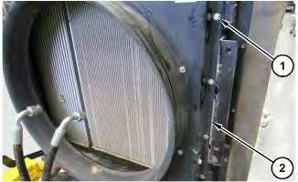
Illustration 1
1. Remove bolts (1) and shroud (2).
This is the sample of the manual click on the download link for complete manual
DOWNLOAD LINK
For some reason if link does not work download this pdf and then click
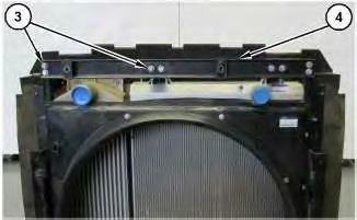
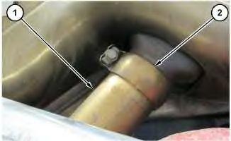
Illustration 2
2. Remove bolts (3) and bracket (4).
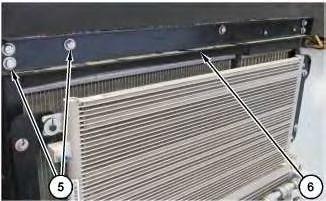
Illustration 3
3. Remove bolts (5) and bracket (6).
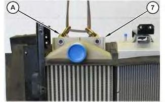
4
4. Attach Tooling (A) and a suitable lifting device to aftercooler core (7).
5. Remove bolt (8) and aftercooler core (7).
Installation Procedure
1. Install aftercooler core (7) in the reverse order of removal.
Copyright 1993 - 2022 Caterpillar Inc. All Rights Reserved. Private Network For SIS Licensees.
Tue May 24 10:25:01 UTC+0530 2022
Product: WHEEL LOADER
Model: 950 GC WHEEL LOADER M5T
Configuration: 950GC Wheel Loader M5T00001-UP (MACHINE) POWERED BY C7.1 Engine
Disassembly and Assembly
950GC Wheel Loader Tier 4 Final
Media Number -M0073302-00
Publication Date -01/10/2014
Air Cleaner - Remove and Install
SMCS - 1051-010
Removal Procedure
Start By:
a. Remove engine enclosure.
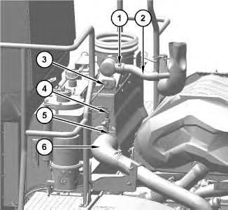
Illustration 1
Date Updated -24/02/2017
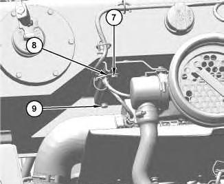
Illustration 2
1. Loosen clamps (1) and (5) and disconnect hoses (2) and (6).
2. Disconnect harness assemblies (3) and (4).
3. Remove bolt (7) and reposition clip (8). Remove bolt (9).
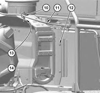
Illustration 3
g06144282
4. Remove bolt (13) and reposition clip (10) and harness assembly (11).
5. Remove bolts (12) and air cleaner (14).
Installation Procedure
1. Install air cleaner (14) in reverse order of removal.
Copyright 1993 - 2022 Caterpillar Inc. All Rights Reserved. Private Network For SIS Licensees.
Tue May 24 10:27:56 UTC+0530 2022
Product: WHEEL LOADER
Model: 950 GC WHEEL LOADER M5T
Configuration: 950GC Wheel Loader M5T00001-UP (MACHINE) POWERED BY C7.1 Engine
Disassembly and Assembly
950GC Wheel Loader Tier 4 Final
Media Number -M0073302-00
Air Inlet Elbow - Remove and Install
SMCS - 1087-010-E4; 1087-010
Removal Procedure
Start By:
a. Remove clean emissions module.
-24/02/2017
Sulfuric Acid Burn Hazard may cause serious personal injury or death.
The exhaust gas cooler may contain a small amount of sulfuric acid. The use of fuel with sulfur levels greater than 15 ppm may increase the amount of sulfuric acid formed. The sulfuric acid may spill from the cooler during service of the engine. The sulfuric acid will burn the eyes, skin and clothing on contact. Always wear the appropriate personal protective equipment (PPE) that is noted on a material safety data sheet (MSDS) for sulfuric acid. Always follow the directions for first aid that are noted on a material safety data sheet (MSDS) for sulfuric acid.
NOTICE
Keep all parts clean from contaminants.
Contaminants may cause rapid wear and shortened component life.
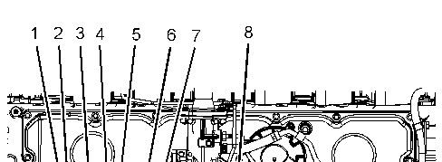
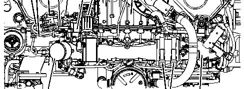
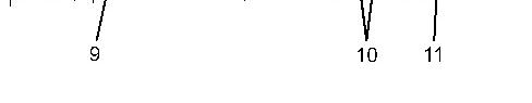
Illustration 1 g03456496
1. Loosen the hose clamps and disconnect the hose assembly from connection (9) for inlet air control (8).
2. Disconnect engine wiring harness assembly (1) from wiring harness assembly (5) for NRS valve (7). Slide the connection for wiring harness assembly (5) from bracket (3).
3. Disconnect engine wiring harness assembly (2) from wiring harness assembly (4) for wastegate solenoid (6). Slide connection for wiring harness assembly (4) from bracket (3).
4. Loosen hose clamps (10) on the hose assembly that connects inlet air control assembly (8) to inlet elbow (11).
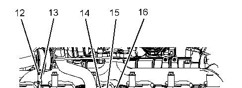
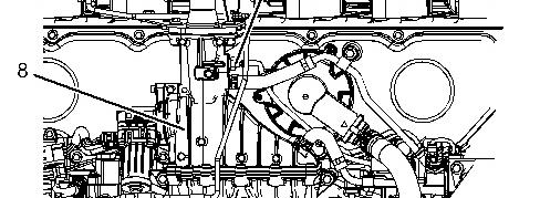
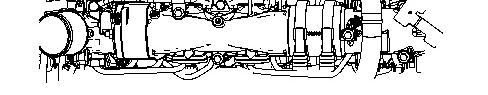
Illustration 2 g03456497
5. Remove temperature sensor (16) from inlet air control assembly (8). Refer to Disassembly and Assembly, "Temperature Sensor (Cooled Exhaust Gas) - Remove and Install" for the correct procedure.
6. Slide clip (12) along hose assembly (13). Disconnect the hose assembly from the wastegate actuator.
7. Remove bolt (15) for the tube assembly for the wastegate actuator.
8. Remove bolts (14).
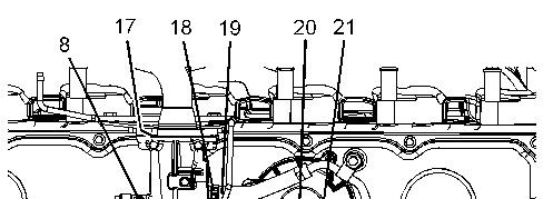
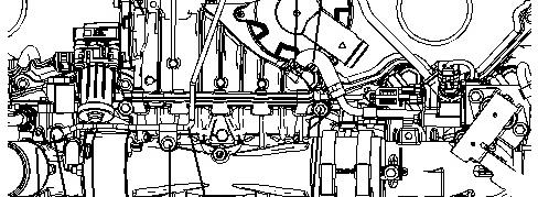
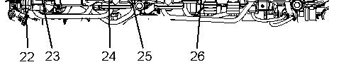
Illustration 3 g03456498
9. Release hose clamp (18) for hose assembly (19). Remove the hose assembly from inlet air control assembly (8).
10. Release hose clamp (20) for hose assembly (21). Remove the hose assembly from inlet air control assembly (8).
11. Remove banjo bolt (23) and remove sealing washers (22) (not shown).
12. Remove bolt (24) from tube assembly (25). Remove the tube assembly from inlet air control assembly (8).
13. Remove bolts (26) inlet air control assembly (8).
14. Remove inlet air control assembly (8).
15. Remove gasket (17) (not shown).
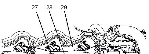

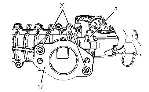
Illustration 4 g03456499
16. Cut cable straps (30).
Remove bolts (27).
Remove bracket (28) from cylinder head (29).
Installation Procedure
Sulfuric Acid Burn Hazard may cause serious personal injury or death.
The exhaust gas cooler may contain a small amount of sulfuric acid. The use of fuel with sulfur levels greater than 15 ppm may increase the amount of sulfuric acid formed. The sulfuric acid may spill from the cooler during service of the engine. The sulfuric acid will burn the eyes, skin and clothing on contact. Always wear the appropriate personal protective equipment (PPE) that is noted on a material safety data sheet (MSDS) for sulfuric acid. Always follow the directions for first aid that are noted on a material safety data sheet (MSDS) for sulfuric acid.
NOTICE
Ensure that wiring harness are correctly routed and the cable straps are not over tightened. Over tightening of the cable straps will damage the wiring harness convoluting.
1. Ensure that all components are clean and free from wear and damage. If necessary, replace any components that are worn or damaged.
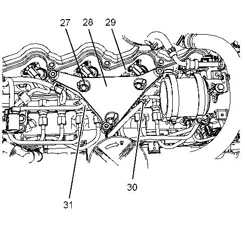
Illustration 5 g03458958
2. If necessary, follow Step 1 through Step4 to install bracket (28).
a. Position bracket (28) onto cylinder head (29).
b. Install bolts (27) hand tight. Ensure that rubber sleeve (31) is correctly positioned into recess of bracket (28).
c. Tighten bolts (27) to a torque of 22 N·m (195 lb in).
d. Install new cable straps (30).
Note: Ensure that the cable straps meet the Original Equipment Manufacturer (OEM) specification.
6

7
3. Position a new gasket (17) onto inlet air control assembly (8). Ensure gasket (17) is correctly installed into locating Pins (X).
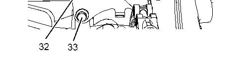
4. Loosen bolts (33) for bracket (32).
8 g03456497
Illustration 9 g03456498
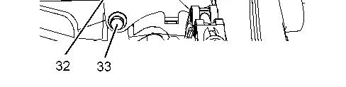
Illustration 10 g03458961
5. Position inlet air control assembly (8) onto the bracket.
Note: Ensure that the inlet air control assembly is correctly installed onto the hose assembly for the inlet elbow.
6. Install bolts (26) to inlet air control assembly (8) hand tight.
7. Install bolts (14) hand tight. Ensure that the gasket (17) remains correctly positioned onto inlet air control assembly (8).
8. Tighten bolts (26) to a torque of 22 N·m (195 lb in).
9. Tighten bolts (14) to a torque of 22 N·m (195 lb in).
10. Tighten bolts (33) for bracket (32) to a torque of 44 N·m (32 lb ft).
11. Position tube assembly (25) onto inlet air control assembly (8). Loosely install bolt (24) and bolt (15) to the tube assembly.
12. Install sealing washer (22) (not shown) to banjo bolt (23). Install the banjo bolt to tube assembly (25) and install remaining sealing washer (22) (not shown) to the banjo bolt.
13. Tighten banjo bolt (23) to a torque of 15 N·m (133 lb in).
14. Tighten bolt (24) and bolt (15) to a torque of 22 N·m (195 lb in).
15. Position a new hose clamp (18) onto hose assembly (19). Install hose assembly to inlet air control assembly (8). Tighten hose clamp (18).
16. Position a new hose clamp (20) onto hose assembly (21). Install hose assembly to inlet air control assembly (8). Tighten hose clamp (20).
17. Install temperature sensor (16) to the inlet air control assembly. Refer to Disassembly and Assembly, "Temperature Sensor (Cooled Exhaust Gas) - Remove and Install" for the correct procedure.
18. Connect hose assembly (13) to the wastegate actuator. Slide clip (12) along hose assembly (13). Ensure that the clip is correctly positioned onto the hose.
11 g03456496
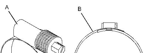
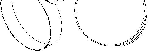

Illustration 12 g02518536
Hose clamp Type (A)
Hose clamp Type (B)
19. Tighten hose clamps (10) on the hose assembly that connects inlet air control assembly (8) to inlet elbow (11). Refer to Illustration 12 to determine the correct type of hose clamp.
Tighten hose clamps Type (A) to a torque of 11 N·m (97 lb in).
Tighten hose clamps Type (B) to a torque of 7 N·m (62 lb in).
20. Slide connection for wiring harness assembly (4) onto bracket (3). Connect engine wiring harness assembly (2) to wiring harness assembly (4) for wastegate solenoid (6).
21. Slide the connection for wiring harness assembly (5) onto bracket (3). Connect engine wiring harness assembly (1) to wiring harness assembly (5) for NRS valve (7).
22. Connect the hose assembly to connection (9) for inlet air control (8). Tighten the hose clamps to a torque of 6 N·m (53 lb in).
23. Install new cable straps to the engine wiring harness assemblies.
Note: Ensure that the cable straps meet the Original Equipment Manufacturer (OEM) specification.
Copyright 1993 - 2022 Caterpillar Inc. All Rights Reserved. Mon May 23 15:04:35 UTC+0530 2022
Product: WHEEL LOADER
Model: 950 GC WHEEL LOADER M5T
Configuration: 950GC Wheel Loader M5T00001-UP (MACHINE) POWERED BY C7.1 Engine
Disassembly and Assembly
950GC Wheel Loader Tier 4 Final
Media Number -M0073302-00 Publication Date -01/10/2014 Date Updated -24/02/2017
Alternator - Remove and Install
SMCS - 1405-010
Removal Procedure
Start By:
a. Turn the battery disconnect switch to the "Off" position.
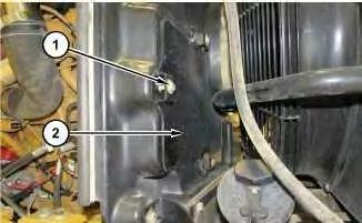
Illustration 1 g06144312
1. Remove bolts (1) and plate (2).
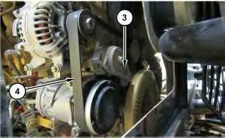
Illustration 2 g06144316
Illustration 3
2. Release tensioner (3) and remove belt (4).
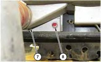
g06144323
3. Disconnect cable assemblies (7) and (8). Remove bolts (5) and alternator (6).
Installation Procedure
1. Install alternator (6) in reverse order of removal.
Copyright 1993 - 2022 Caterpillar Inc. All Rights Reserved. Private Network For SIS Licensees. Mon May 23 14:45:12 UTC+0530 2022
Product: WHEEL LOADER
Model: 950 GC WHEEL LOADER M5T
Configuration: 950GC Wheel Loader M5T00001-UP (MACHINE) POWERED BY C7.1 Engine
Disassembly and Assembly
950GC Wheel Loader Tier 4 Final
Media Number -M0073302-00
Publication Date -01/10/2014
Batteries - Remove and Install
SMCS - 1401-010; 1408-010
Removal Procedure
1. Turn the battery disconnect switch to the OFF position.
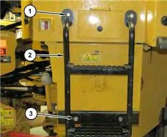
Illustration 1
g06143114
2. Remove bolts (1) and (3). Remove ladder (2).
Date Updated -24/02/2017
2
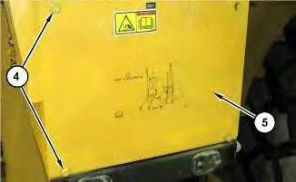
3. Remove bolts (4) and cover (5).
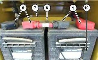
Illustration 3
4. Remove battery cables (6) and, (9). Remove nut (8) and plate (7). Remove batteries (10).
Installation Procedure
1. Install batteries (10) in reverse order of removal.
Copyright 1993 - 2022 Caterpillar Inc. All Rights Reserved. Private Network For SIS Licensees. Mon May 23 14:42:31 UTC+0530 2022
Product: WHEEL LOADER
Model: 950 GC WHEEL LOADER M5T
Configuration: 950GC Wheel Loader M5T00001-UP (MACHINE) POWERED BY C7.1 Engine
Disassembly and Assembly
950GC Wheel Loader Tier 4 Final
Media Number -M0073302-00 Publication Date -01/10/2014 Date Updated -24/02/2017
Clean Emissions Module - Remove and Install
SMCS - 1050; 7279
Removal Procedure Table 1
Required Tools Tool Part Number Part Description Qty A 189-0408 Shackle 2
Start By:
a. Remove engine enclosure.
Personal injury or death may result from failure to adhere to the following procedures.
Fuel leaked or spilled onto hot surfaces or electrical components can cause a fire.
Clean up all leaked or spilled fuel. Do not smoke while working on the fuel system.
Turn the disconnect switch OFF or disconnect the battery when changing fuel filters.
Hot engine components can cause injury from burns. Before performing maintenance on the engine, allow the engine and the components to cool.
Wear goggles, gloves, protective clothing, and a National Institute for Occupational Safety and Health (NIOSH) approved P95 or N95 halfface respirator when handling a used Diesel Particulate Filter or Catalytic Converter Muffler. Failure to do so could result in personal injury.
1. Turn the fuel supply to the OFF position and turn the power disconnect switch to the OFF position.
2. Drain the coolant just below the level of the clean emissions module. Refer to Operation and Maintenance Manual, "Cooling System Coolant (ELC) - Change" for the correct draining and filling procedure.
This is the sample of the manual click on the download link for complete manual
DOWNLOAD LINK
For some reason if link does not work download this pdf and then click