

Product: WHEEL LOADER
Model: 938G II WHEEL LOADER B9Y
Configuration: 938G SERIES II WHEEL LOADER B9Y00001-UP (MACHINE) POWERED BY 3126B ENGINE
Disassembly and Assembly
938G Series II Wheel Loader and IT38G Series II Integrated Toolcarrier Power Train
Axle Housing - Assemble
Assembly Procedure
Table 1
Required Tools
This is the sample of the manual click on the download link for complete manual
DOWNLOAD LINK
For some reason if link does not work download this pdf and then click
Note: The axle housing assemblies that are used in the fixed axle and in the oscillating axle are similar. Therefore, both axle assemblies can be assembled in the same manner.
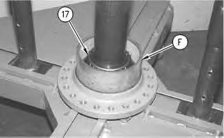
Illustration 1
1. Use bolts of a suitable size to fasten the rim of the axle shaft to Tooling (B).
2. Heat bearing cone (17) to a maximum temperature of 135°C (275°F).
3. Install bearing cone (17) on the axle shaft, as shown. Make sure that the bearing cone is seated against the shoulder.
Note: Allow the bearing cone and the axle to reach a uniform temperature.
4. Use a suitable driver or a press to reset the bearing cone. This will ensure that the bearing cone is seated properly.
5. Apply a thin coat of clean SAE 30 oil on bearing cone (17).
Note: Make sure that the rubber seals and all surfaces that contact the seals are clean and dry. After installation of the seals, apply clean SAE 30 oil on the contact surfaces of the metal seals.
6. Use Tooling (F) to install the Duo-Cone seal in the axle assembly. Refer to Disassembly and Assembly, "Duo-Cone Conventional Seals - Install".
2
7. Lower the temperature of bearing cup (16). Install bearing cup (16) in the end of the axle housing. Make sure that the bearing cup is seated with the mating surface.
Note: Allow the bearing cone and the axle to reach a uniform temperature.
8. Use a suitable driver or a press to reset bearing cup (16). This will ensure that bearing cup (16) is seated properly.
Note: Make sure that the rubber seals and all surfaces that contact the seals are clean and dry. After installation of the seals, apply clean SAE 30 oil on the contact surfaces of the metal seals.
9. Use Tooling (F) to install Duo-Cone seal (15) in the end of the axle housing. Refer to Disassembly and Assembly, "Duo-Cone Conventional Seals - Install".
10. Lower the temperature of bearing cup (13). Install bearing cup (13) in the opposite end of the axle housing, as shown. Make sure that the bearing cup is seated on the mating surface.
Note: Allow the bearing cone and the axle to reach a uniform temperature.
11. Use a suitable driver or a press to reset bearing cup (12). This will ensure that bearing cup (12) is seated properly.
Note: The following steps are for the installation of the ring gear.
Note: Dowels (14) are used to locate ring gear (15).
12. Locate the position of the ring gear in relation to the axle housing. Align the holes to install the dowels. Put alignment marks on the ring gear and on the axle housing to ensure correct installation.
13. housing.
14. Install dowels (14). Peen the axle housing near the dowels to retain the dowels.
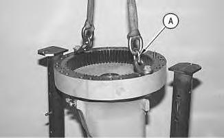
Illustration 4
g00303176
15. Install Tooling (A) on the axle housing, as shown. Attach a hoist and suitable lifting slings to Tooling (A).
16. Use the hoist to install the axle housing on the axle shaft. The weight of the axle housing is 105 kg (231 lb).
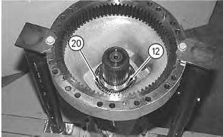
Illustration 5
g00311444
17. Heat bearing cone (20) to a maximum temperature of 135°C (275°F).
18. Install bearing cone (20) on the axle shaft so that there is slight end play. When bearing cone (20) is cool, apply clean SAE 30 oil to the bearing cone.
Note: The adjusting nut must be installed so that the part number is facing away from bearing cone (20).
19. Apply clean SAE 30 oil on bearing nut (12). Install bearing nut (12) on the axle shaft. Tighten the nut until a small amount of end play remains.
20. The seal drag torque is the torque that is needed to rotate the axle housing. Use one of the following methods to measure the seal drag torque:
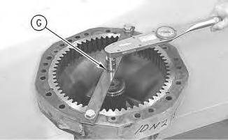
Illustration 6
g00311446
a. To measure seal drag torque, install Tooling (G) on the axle housing. Place a torque wrench on the bolt at the center of the bar, as shown. Use the torque wrench to rotate the housing. Record the reading on the torque wrench.

Illustration 7
g00311903
b. To measure seal drag torque, install a bolt and a nut through an outer mounting hole on the axle housing. Install a torque wrench on the bolt. Make sure that the handle is aligned with the center of the axle shaft. Use the torque wrench to rotate the housing. Record the reading on the torque wrench. Use the following formula to calculate the actual seal drag torque:
Table 2 B
"SDT" is the actual seal drag torque in newton meters (N·m).
"C" is the torque wrench reading in newton meters (N·m).
"B" is the length of the torque wrench in meters.
"A" is the bolt circle radius of axle housing (2) in meters. This is equal to 0.229 m (9.016 inch).
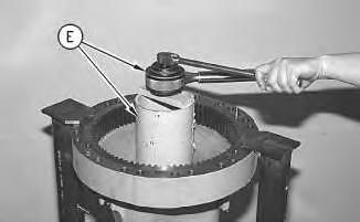
21. Tighten nut (11) by using one of the following methods:
8
Illustration 9
a. Rotate the axle housing. Use Tooling (E) to tighten bearing nut (11). Install Tooling (G) on the axle housing. Place a torque wrench on the bolt at the center of Tooling (G). The torque wrench reading is equal to the seal drag torque plus the axle bearing preload rolling torque. Use the seal drag torque that was recorded in Step 20.
Note: The preload rolling torque for new bearings is 9 to 16 N·m (7 to 12 lb ft). The preload rolling torque for used bearings is 4.5 to 8 N·m (3.5 to 6 lb ft).
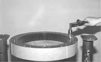
Illustration 10
g00311903
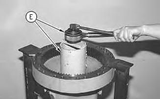
Illustration 11
g00303174
b. Use the torque wrench to rotate the axle housing. Use Tooling (E) to tighten nut (11). The torque wrench reading must equal the axle bearing preload rolling torque plus the actual seal drag torque. Use the seal drag torque that was recorded in Step 20. Use the following formula to calculate the required torque wrench reading. This formula is used to measure torque at the bolt circle.
Table 3
B + A
"C" is the torque wrench reading in newton meters (N·m).
"B" is the length of the torque wrench in meters.
"A" is the bolt circle radius of axle housing (2) in meters. This equals 0.229 m (9.016 inch).
"SDT" is the actual seal drag torque in newton meters (N·m).
"T" is the axle bearing preload rolling torque. The preload rolling torque for new bearings is 9 to 16 N·m (7 to 12 lb ft). The preload rolling torque for used bearings is 4.5 to 8 N·m (3.5 to 6 lb ft).
22. Make sure that axle shaft (4) has zero end play.
23. If the axle bearing preload rolling torque exceeds the specification, back off nut (11) by 1/8 turn and reseat bearing cone (13) against nut (11). Perform Step 21 again.
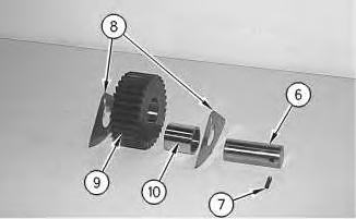
Illustration 12
g00303171
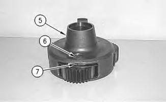
Illustration 13
g00303170
24. The following steps are for the assembly of planetary carrier assembly (5):
a. Install retaining ring (3) in the carrier.
b. Apply a thin coat of clean SAE 30 oil on all parts of planetary carrier assembly (5).
c. Install bearing (10) in planetary gear (9).
d. Install thrust washers (8), planetary gear (9), and shaft (7) in the carrier.
Note: If thrust washers (8) have alignment tabs, the alignment tabs should be installed towards the center of the carrier.
e. Install shaft (6) in the carrier. Make sure that the spring pin hole in the shaft is aligned with the spring pin hole in the carrier. Install new spring pin (7) through the carrier and in shaft (6). Install spring pin (7) slightly below the outside surface of the carrier.
f. Repeat Steps 24.a through 24.e for the remaining two planetary gears.

Illustration 14
g00303169
25. Install Tooling (D) and suitable lifting slings to planetary carrier assembly (5).
26. Use a hoist to install the planetary carrier assembly in the axle housing assembly. The weight of the planetary carrier assembly is 80 kg (175 lb).

Illustration 15
g00303124
27. Use Tooling (C) to install retaining ring (3) on axle shaft (4).
28. Remove axle housing assembly (2) from Tooling (B). Install the bottom half of the axle group on Tooling (B) in a vertical position.
29. Apply 6V-6640 RTV Silicone Sealant on the mating surfaces of the axle housing and of the differential housing.
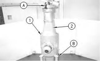
Illustration 16
30. Apply a thin layer of Tooling (H) to the mating surface of the axle housing. Attach Tooling (A) and a suitable lifting device to axle housing assembly (2). The weight of axle housing assembly (2) is approximately 295 kg (650 lb). Carefully install the axle housing assembly.
31. Install bolts (1) that secure axle housing assembly (2) to the differential housing. Tighten bolts (1) to a torque of 300 ± 40 N·m (220 ± 30 lb ft).
End By:
a. Install the fixed axle. Refer to Disassembly and Assembly, "Fixed Axle (Front) - Remove and Install".
b. Install the oscillating axle. Refer to Disassembly and Assembly, "Oscillating Axle (Rear)Install".
Sat Nov 27 16:42:03 UTC+0530 2021
Product: WHEEL LOADER
Model: 938G II WHEEL LOADER B9Y
Configuration: 938G SERIES II WHEEL LOADER B9Y00001-UP (MACHINE) POWERED BY 3126B ENGINE
Disassembly and Assembly
938G Series II Wheel Loader and IT38G Series II Integrated Toolcarrier Power Train
Axle Housing - Disassemble
Disassembly Procedure
Table 1 Required Tools
(1) For use with M105 bearing nut.
(2) For use with M95 bearing nut.
Start By:
a. Remove the fixed axle. Refer to Disassembly and Assembly, "Fixed Axle (Front) - Remove and Install".
b. Remove the oscillating axle. Refer to Disassembly and Assembly, "Oscillating Axle (Rear)Remove".
Note: The axle housing assemblies that are used in the front fixed axle and in the rear oscillating axle are similar. Therefore, both axle housing assemblies can be removed in the same manner.
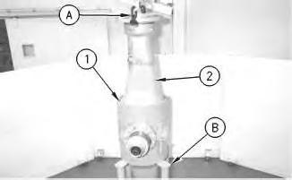
Illustration 1
Typical Example
g00301040
1. Install the axle housing in a vertical position on Tooling (B).
Note: Carefully remove the axle housing assembly. Part of the wear gauge pin will remain in the axle housing assembly. The pin will remain in the axle housing assembly. The spring and the piston will remain in the differential housing.
2. Fasten Tooling (A) and a hoist to the rim of the axle shaft, as shown. Remove bolts (1) that secure axle housing assembly (2) to the differential housing. Carefully remove the axle housing assembly. The weight of axle housing assembly (2) is 295 kg (650 lb).
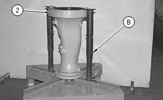
Illustration 2
3. Remove the bottom half of the axle housing from Tooling (B). Install axle housing assembly (2) on Tooling (B), as shown.
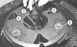
Illustration 3
Note: To remove retaining ring (3), planetary carrier assembly (5) must be disassembled.
4. Use Tooling (C) to remove retaining ring (3) from axle shaft (4).
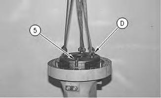
Illustration 4
5. Install Tooling (D) and suitable lifting slings to planetary carrier assembly (5), as shown.
6. Use a hoist to remove the planetary carrier assembly from the axle housing assembly. The weight of the planetary carrier assembly is 80 kg (175 lb).
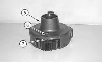
Illustration 5
g00303170

Illustration 6
g00303171
7. Use the following steps to disassemble planetary carrier assembly (5):
a. Use a hammer and a punch to push spring pin (7) all the way into shaft (6).
b. Remove shaft (6), thrust washers , and (8) planetary gear (9) from the carrier.
c. Remove bearing (10) from planetary gear (9).
d. Use a hammer and a punch to remove spring pin (7) from shaft (6).
e. Repeat Steps 7.a through 7.d for the remaining two planetary gears.
f. Remove retaining ring (3) from the carrier.
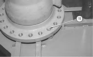
Illustration 7
g00303172
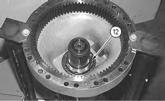
Illustration 8
g00303173
8. Install two bolts (11) of a suitable size in the rim of the axle flange. This will prevent the axle shaft from turning when bearing nut (12) is removed.
Illustration 9
g00303174
9. Use Tooling (E) to remove bearing nut (12) from the axle shaft.
10 g00303176
10. Install Tooling (A) and suitable lifting slings to the axle housing, as shown. Put slight lifting tension on the axle housing.
11
Note: The bearing cone which is located under bearing nut (12) will be removed at the same time as the axle housing.
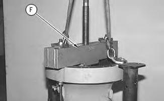
11. Fasten Tooling (F) to the axle housing, as shown. Use the center stud to push the axle shaft and the bearing cone from the axle housing. Make sure that upward pressure is constantly applied.
12. Use the hoist to remove the axle housing and the inner bearing cone from the axle shaft. The weight of the axle housing is 105 kg (231 lb).
13. Remove the inner bearing cone from the axle housing.
12
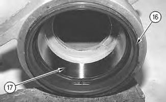
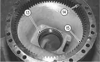
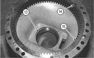
14. Remove inner bearing cup (13) from the axle housing.
Note: Planetary ring gear (15) will be destroyed during removal.
15. Remove ring gear (15) from the axle housing. Use a torch to cut the ring gear in two places that are directly across from each other. Cut the ring gear at the position of the locating dowels. For an alternate method, make three welds that are equally spaced around the circumference of the ring gear. This will cause the ring gear to shrink.
16. Remove dowels (14).
Illustration 13
17. Remove Duo-Cone seal (16) and bearing cup (17) from the opposite end of the axle housing.
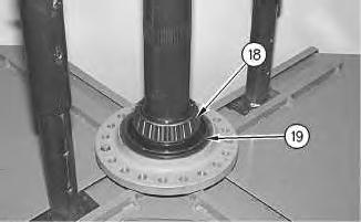
Illustration 14
g00303181
18. Remove Duo-Cone seal (19) and bearing cone (18) from the axle shaft.
Copyright 1993 - 2021 Caterpillar Inc. All Rights Reserved.
Private Network For SIS Licensees.
Sat Nov 27 16:41:29 UTC+0530 2021
Product: WHEEL LOADER
Model: 938G II WHEEL LOADER B9Y
Configuration: 938G SERIES II WHEEL LOADER B9Y00001-UP (MACHINE) POWERED BY 3126B ENGINE
Disassembly and Assembly
938G Series II Wheel Loader and IT38G Series II Integrated Toolcarrier Power Train
Media
Bottom Guard (Engine) - Remove and Install
SMCS - 7153-010
Removal Procedure
Table 1
Required Tools
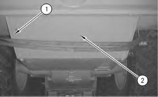
Illustration 1
1. Use suitable lifting straps to support plate (2). Remove bolts (1) and remove plate (2). The weight of plate (2) is approximately 27 kg (60 lb).
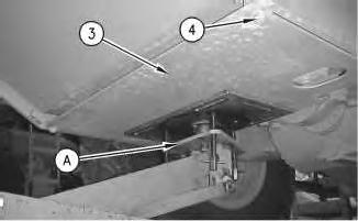
Illustration 2
2. Support bottom guard (3) with Tooling (A). Remove bolts (4). Remove bottom guard (3). The weight of bottom guard (3) is approximately 45 kg (100 lb).
Installation Procedure
Table 2 Required Tools
Tool Part Number Part Description Qty
A 1U-7505 Hydraulic Jack 1
Illustration 3
1. Support bottom guard (3) with Tooling (A). Install bottom guard (3). Install bolts (4). The weight of bottom guard (3) is approximately 45 kg (100 lb).
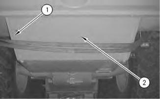
Illustration 4 g00978826
2. Use suitable lifting straps to support plate (2). Install plate (2) and install bolts (1). The weight of plate (2) is approximately 27 kg (60 lb).
Copyright 1993 - 2021 Caterpillar Inc.
All Rights Reserved.
Private Network For SIS Licensees.
Sat Nov 27 16:30:46 UTC+0530 2021
Product: WHEEL LOADER
Model: 938G II WHEEL LOADER B9Y
Configuration: 938G SERIES II WHEEL LOADER B9Y00001-UP (MACHINE) POWERED BY 3126B ENGINE
Disassembly and Assembly
938G Series II Wheel Loader and IT38G Series II Integrated Toolcarrier Power Train
Media Number -RENR6068-03
Publication Date -01/12/2008
Differential - Assemble
SMCS - 3258-016
Assembly Procedure
1. Align marks on housings.
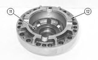
Illustration 1
g00334077
2. Install thrust washer (11) in case assembly (12).
Date Updated -19/12/2008
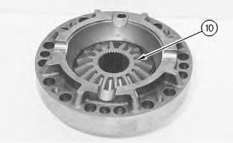
Illustration 2
g00334075
3. Install bevel gear (10) in the case assembly.
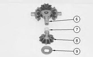
Illustration 3
g00334074
4. Install sleeve bearings (7), pinion gears (8), and thrust washers (9) on spider (6).
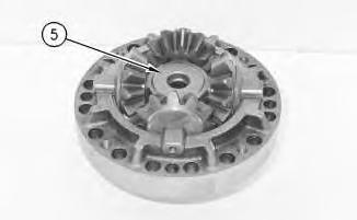
Illustration 4
5. Install spider gear assembly (5).
g00334073
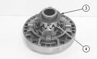
Illustration 5 g00334072
6. Install bevel gear (4) and thrust washer (3).
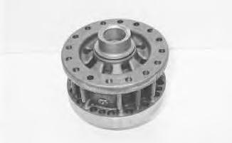
Illustration 6
7. Install top half of the case assembly.
g00859593
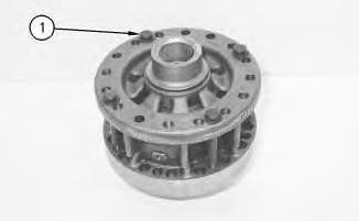
Illustration 7 g01001783
A new differential group or a new case assembly will be equipped with four bolts and washers that are used for shipping, assembly, and storage purposes only. Remove and discard these four bolts and washers after the bevel gear has been installed. These four bolts and washers should not be used for final assembly.
8. Install bolts (1) and the washers in order to hold the two halves of the differential case together. Bolts (1) and washers are used to hold the differential case together until final assembly. Remove bolts (1) and washers and discard bolts (1) and washers after installation of the bevel gear.
End By:
a. Install the differential and the bevel gear. Refer to Disassembly and Assembly, "Differential and Bevel Gear - Install".
Copyright 1993 - 2021 Caterpillar Inc. All Rights Reserved.
Private Network For SIS Licensees. Sat Nov 27 16:43:50 UTC+0530 2021
This is the sample of the manual click on the download link for complete manual
DOWNLOAD LINK
For some reason if link does not work download this pdf and then click