
Product: COMPACT WHEEL LOADER
Model: 906 COMPACT WHEEL LOADER MER
Configuration: 906 Wheel Loader MER00001-UP (MACHINE) POWERED BY 3044C Engine
Disassembly and Assembly
906 and 908 Compact Wheel Loaders 3044C Engine Supplement
Air Cleaner - Remove and Install
SMCS - 1051-010
Removal Procedure
Hot engine components can cause injury from burns. Before performing maintenance on the engine, allow the engine and the components to cool.
1. Open the hood and the access panel on the left side of the machine.
2. Turn the battery disconnect switch to the OFF position.
1
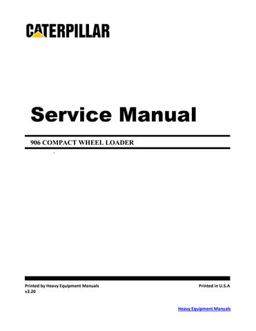
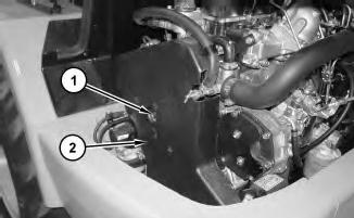
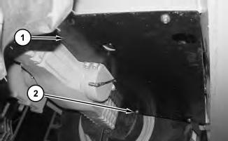
3. Remove cover (2) from air cleaner housing (1) .
2
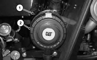
4. Remove primary air filter element (3) from air cleaner housing (1) .
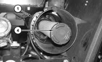
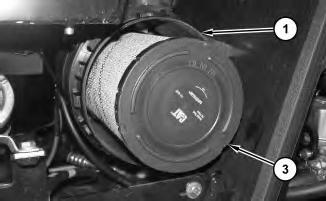
Illustration 3
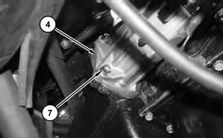
5. Remove secondary air filter element (4) from air cleaner housing (1) .
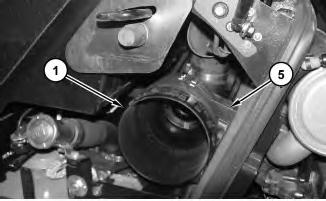
Illustration 4
6. Remove bolts (5) from air cleaner housing (1) .
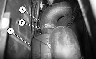
Illustration 5
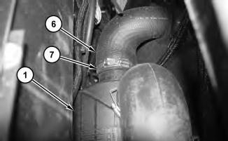
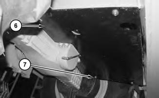
7. Loosen clamp (7) and remove hose (6) from air cleaner housing (1) .
This is the sample of the manual click on the download link for complete manual
DOWNLOAD LINK
For some reason if link does not work download this pdf and then click
6
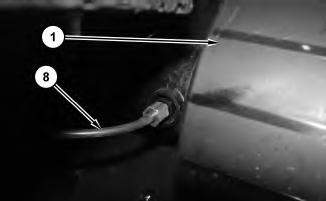
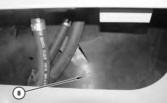
8. Disconnect tube assembly (8) and remove air cleaner housing (1) .
Installation Procedure
Illustration 7
1. Install air cleaner housing (1) and connect tube assembly (8) .
8
9
Illustration 10
4. Install secondary air filter element (4) in air cleaner housing (1) .
Illustration 11 g01318230
5. Install primary air filter element (3) in air cleaner housing (1) .

Illustration 12 g01318228
6. Install cover (2) on air cleaner housing (1) .
7. Turn the disconnect switch to the ON position.
8. Close the access panel on the left side of the machine and the hood.
Product: COMPACT WHEEL LOADER
Model: 906 COMPACT WHEEL LOADER MER
Configuration: 906 Wheel Loader MER00001-UP (MACHINE) POWERED BY 3044C Engine
Disassembly and Assembly
906 and 908 Compact Wheel Loaders 3044C Engine Supplement
i02629023
Alternator - Remove and Install
SMCS - 1405-010
Removal Procedure
Hot engine components can cause injury from burns. Before performing maintenance on the engine, allow the engine and the components to cool.
1. Open the hood.
2. Turn the battery disconnect switch to the OFF position.
1
3. Remove bolts (1) and cover (2) .
2
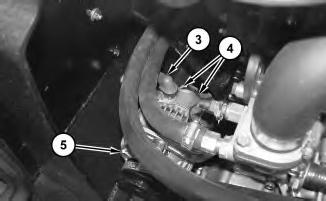
4. Disconnect cable assembly (3) and harness assemblies (4) from alternator (5) .
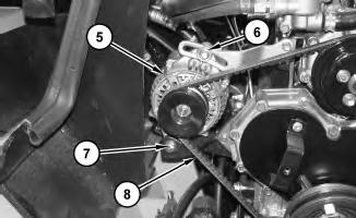
Illustration 3
5. Loosen bolt (6) and bolt (7). Remove belt (8) from alternator (5). Remove bolt (6), bolt (7), and alternator (5) .
Installation Procedure

Illustration 4
g01318371
1. Install alternator (5), bolt (6), bolt (7), and belt (8) .
2. Refer to Operation and Maintenance Manual for the correct tightening procedure for the alternator belt.
3. Tighten bolt (6) and bolt (7) .
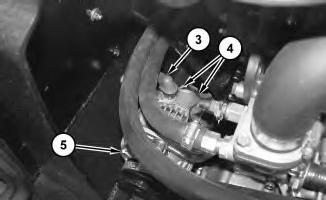
Illustration 5
g01318370
4. Connect harness assemblies (4) and cable assembly (3) to alternator (5) .
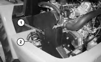
Illustration 6
5. Install cover (2) and bolts (1) .
6. Turn the disconnect switch to the ON position.
7. Close the hood.
Copyright 1993 - 2021 Caterpillar Inc. All Rights Reserved. Private Network For SIS Licensees. Tue Mar 9 12:12:43 UTC+0530 2021
Product: COMPACT WHEEL LOADER
Model: 906 COMPACT WHEEL LOADER MER
Configuration: 906 Wheel Loader MER00001-UP (MACHINE) POWERED BY 3044C Engine
Disassembly and Assembly
906 and 908 Compact Wheel Loaders 3044C Engine Supplement
Battery and Battery Cable - Separate and Connect
SMCS - 1401-029-KA
Separation Procedure
Start By:
i02628926
A. Connect the steering frame lock. Refer to Disassembly and Assembly, "Steering Frame LockSeparate and Connect" for the machine that is being serviced.
1. Lower the work tool to the ground.
2. Engage the parking brake.
3. Open the access door on the left side of the machine. Turn the battery disconnect switch to the OFF position.
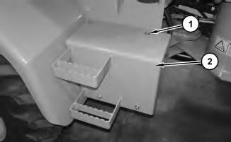
Illustration 1
4. Remove bolts (1) and cover (2) .

2
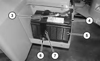
5. Disconnect negative battery cable (4) from battery (5) .
6. Disconnect positive battery cable (3) from battery (5) .
7. Remove bolt (6) and bracket (7). Remove battery (5) .
Connection Procedure
3
1. Install battery (5). Install bracket (7) and bolt (6) .
2. Connect positive battery cable (3) to battery (5) .
3. Connect negative battery cable (4) to battery (5) .
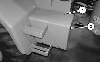
Illustration 4
4. Install cover (2) and bolts (1) .
5. Turn the battery disconnect switch to the ON position. Close the access panel.
6. Disengage the parking brake.
End By: Disconnect the steering frame lock. Refer to Disassembly and Assembly, "Steering Frame Lock - Separate and Connect" for the machine that is being serviced.
Product: COMPACT WHEEL LOADER
Model: 906 COMPACT WHEEL LOADER MER
Configuration: 906 Wheel Loader MER00001-UP (MACHINE) POWERED BY 3044C Engine
Disassembly and Assembly
906 and 908 Compact Wheel Loaders 3044C Engine Supplement
Electric
Starting
SMCS - 1453-010
Motor - Remove and Install
Removal Procedure
Hot engine components can cause injury from burns. Before performing maintenance on the engine, allow the engine and the components to cool.
1. Remove bolts (2) and cover (1) .

2
2. Move cover (3) out of the way.

Illustration 3
3. Remove the nut and disconnect cable assemblies (5) from electric starting motor (4) .
4. Disconnect harness assembly (6) from electric starting motor (4) .
4
5. Remove nuts (7) and remove electric starting motor (4) .
Installation Procedure
5
1. Install electric starting motor (4) and nuts (7) .
6
2. Connect harness assembly (6) to electric starting motor (4) .
3. Connect cable assemblies (5) to electric starting motor (4) and install the nut.

7
.
8 g01318437
5. Install cover (2) and bolts (1) .
6. Turn the disconnect switch to the ON position.
7. Close the hood.
Copyright 1993 - 2021 Caterpillar Inc.
All Rights Reserved.
Private Network For SIS Licensees.
Tue Mar 9 12:13:00 UTC+0530 2021
Product: COMPACT WHEEL LOADER
Model: 906 COMPACT WHEEL LOADER MER
Configuration: 906 Wheel Loader MER00001-UP (MACHINE) POWERED BY 3044C Engine
Disassembly and Assembly
906 and 908 Compact Wheel Loaders 3044C Engine Supplement
i02634634
Engine - Install
SMCS - 1000-012
Installation Procedure
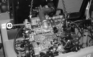
Illustration 1
2
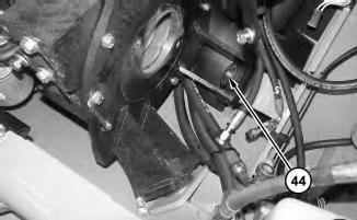
1. Attach a suitable lifting device to engine (43). Install the engine in the machine and install bolts (44). The weight of the engine is approximately 317 kg (700 lb).
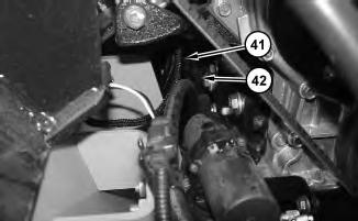
Illustration 3
g01320837
2. Reposition hose assembly (41). Install clamp (42) and the bolt.
4
5
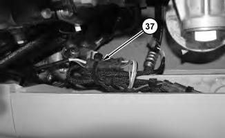
Illustration 6
5. Connect harness assembly (37) and install the cable straps.
7
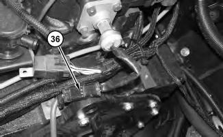
6. Connect harness assembly (36) .
8
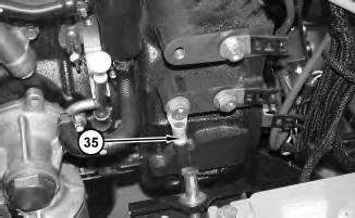
7. Install cable assembly (35) and the bolt.
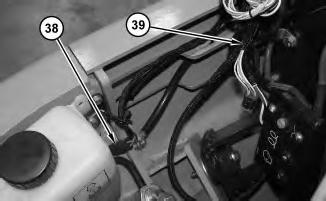
9
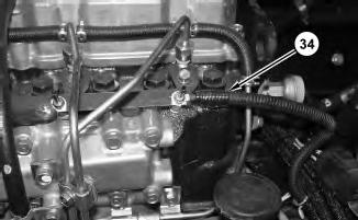
8. Connect harness assembly (34) and install the nut.
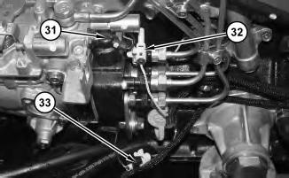
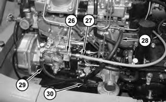
Illustration 11
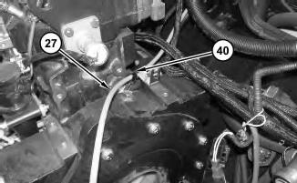
10. Install clamp (30) to the engine. Connect hose (29) and hose (28) to the engine and tighten the clamps.
11. Install throttle cable (27) to the engine and tighten nut (26) .
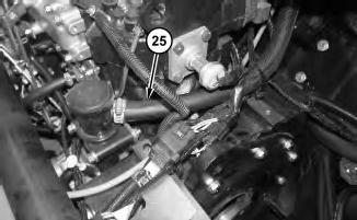
Illustration 12
12. Connect hose (25) and tighten the clamp.
g01320822
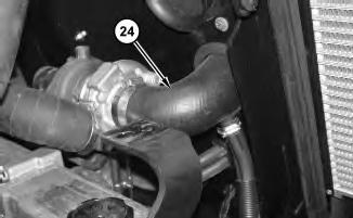
Illustration 13
13. Connect hose (24) to the turbocharger and tighten the clamp.
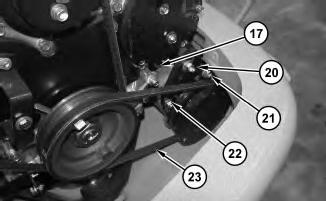
14. Reposition refrigerant compressor (17) and install bolt (21) and bolt (22) .
15. Install belt (23) on the refrigerant compressor. Refer to Operation and Maintenance Manual for the correct tightening procedure for the belt. Tighten bolt (20) .
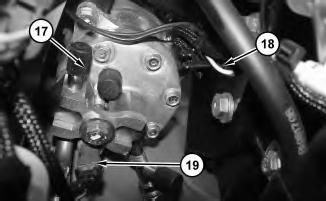
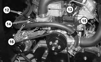
17. Install hoses (16) in bracket (12). Connect hoses (16) to the engine and tighten the clamps.
18. Connect hose (13) and hose (15) to the engine and tighten the clamps.
19. Connect harness assembly (14) .
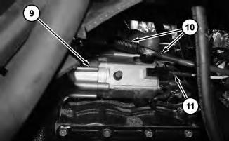
20. Connect harness assembly (11) to electric starting motor (9) .
21. Connect cable assemblies (10) to electric starting motor (9) and install the nut.
This is the sample of the manual click on the download link for complete manual
DOWNLOAD LINK
For some reason if link does not work download this pdf and then click