

Previous Screen

Product: ARTICULATED TRUCK
Model: 740C ARTICULATED TRUCK LFN
Configuration: 740C Ejector Articulated Truck LFN00001-UP (MACHINE) POWERED BY C18 Engine
Disassembly and Assembly
735C, 740C EJECTOR and 745C Articulated Trucks Machine Systems
Media Number -UENR4228-00
Steering Cylinder - Remove and Install
SMCS - 4303-010
Removal Procedure
Failure to relieve pressure before removing a lock valve or disassembling a cylinder can result in personal injury or death.

i06248828
Ensure all pressure is relieved before removing a lock valve or disassembling a cylinder.
At operating temperature, the hydraulic tank is hot and under pressure. Hot oil and components can cause personal injury. Do not allow hot oil or components to contact skin.
Remove the filler cap only when the engine is stopped, and the filler cap is cool enough to touch with your bare hand. Remove the filler cap slowly in order to relieve pressure.
NOTICE
Care must be taken to ensure that fluids are contained during performance of inspection, maintenance, testing, adjusting, and repair of the product. Be prepared to collect the fluid with suitable containers before opening any compartment or disassembling any component containing fluids.
Refer to Special Publication, NENG2500, "Dealer Service Tool Catalog" for tools and supplies suitable to collect and contain fluids on Cat® products.
Dispose of all fluids according to local regulations and mandates.
1. Use Tooling (D) in order to chock the front and rear of the machine.
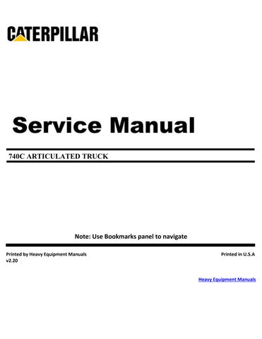
2. If necessary, disconnect grease hose assembly (2). Remove bolt (3) and the washer. Set the grease line bracket to the side. Remove washer (4).
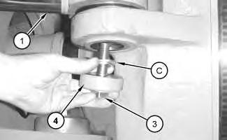
Illustration 2
g03871299
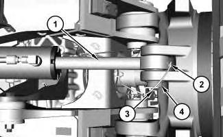
3. Place Tooling (C) on the top of washer (4). Install bolt (3), the washer, and washer (4) back into the rod end of steering cylinder (1).
Illustration 3
g01094620
4. Use Tooling (A) in order to exert a force onto pin (6). Strike mounting bracket (5) for steering cylinder (1) in order to help release pin (6).
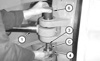
Illustration 4
g03871303
5. Remove bolt (3), the washer, and washer (4) and Tooling (C) from pin (6) at the rod end of steering cylinder (1). If necessary, install the bolt and Tooling (C) back into the pin and use Tooling (A) to fully remove the pin from the machine.
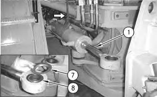
6. Use a suitable prybar in order to remove the steering cylinder from the mounting bracket at the rod end of steering cylinder (1). Carefully swing the rod end of the steering cylinder away from the machine.
7. Remove two face seals (7) and two O-ring seals (8) from both sides of the eye. Attach a suitable lifting device to steering cylinder (1). The weight of steering cylinder (1) is approximately 85 kg (187 lb).
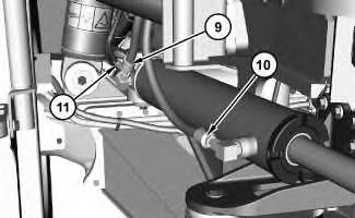
8. Disconnect hose assemblies (9) and (10) from the head end of steering cylinder (1). Disconnect grease hose assembly (11) from the head end of the steering cylinder.
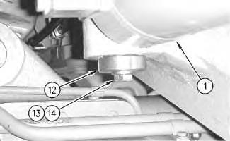
Illustration 7
g00853776
9. Remove bolt (13), washer (14) and washer (12) from the pin at the head end of steering cylinder (1).
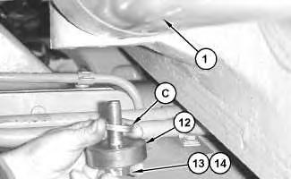
Illustration 8
g01094628
10. Place Tooling (C) on the top of washer (12). Install bolt (13), washer (14), washer (12) and Tooling (C) back into the pin at the head end of the steering cylinder.
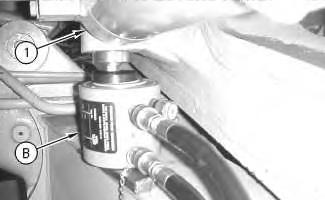
Illustration 9
g00853782
11. Use Tooling (B) in order to exert a force onto the pin in the head end of steering cylinder (1). Strike the mounting bracket for the steering cylinder in order to help release the pin.
Note: Place a suitable wedge between Tooling (B) and the A-frame in order to align Tooling (B) with the pin.
12. Remove bolt (13), washer (14), washer (12) and Tooling (C) from the pin at the head end of steering cylinder (1). If necessary, install the bolt and Tooling (C) back into the pin and use Tooling (B) to fully remove the pin from the machine.
10
11
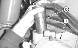
13. Remove pin (15) from the head end of steering cylinder (1). Remove Tooling (B) from the machine. Remove bolt (13), washer (14), washer (12), washers (5), and Tooling (C) from the head end of the steering cylinder.
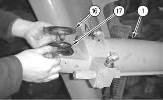
14. Use a suitable lifting device to carefully move steering cylinder (1) away from the machine. Remove two face seals (16) and two O-ring seals (17) from both sides of the head end of the steering cylinder. Place the steering cylinder on suitable cribbing.
Disassembly and Assembly Information
Cylinders equipped with lock valves can remain pressurized for very long periods of time, even with the hoses removed.
Failure to relieve pressure before removing a lock valve or disassembling a cylinder can result in personal injury or death.
Ensure all pressure is relieved before removing a lock valve or disassembling a cylinder.
Note: Cleanliness is an important factor. Before you begin the disassembly procedure, the exterior of the components should be thoroughly cleaned. This will help to prevent dirt from entering the internal mechanism. Precision components can be damaged by contaminants or by dirt. Perform disassembly procedures on a clean work surface. Keep components covered and protected at all times.
Note: Cleanliness is an important factor. Before assembly, all parts should be thoroughly cleaned in cleaning fluid. Allow the parts to air dry. Wiping cloths or rags should not be used to dry parts. Lint may be deposited on the parts which may cause later trouble. Inspect all parts. If any parts are worn or damaged, use new parts for replacement.
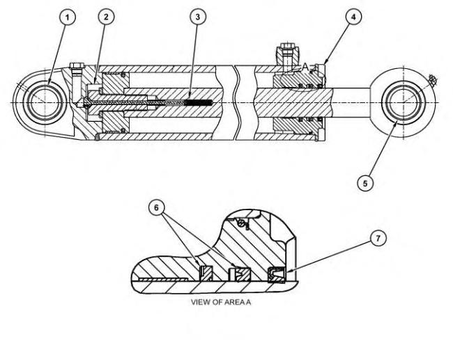
Illustration 13
(1) Use Tooling (G) in order to remove the bearing and install the bearing.
g03871179
(2) Tighten the bolt to a torque of 1600 ± 200 N·m (1180 ± 150 lb ft). Replace a bolt that has been loosened or removed with a new bolt. Install the bolt with threads that are clean and free of lubricant.
(3) Tighten the locknut to a torque of 8 ± 1.5 N·m (71 ± 13 lb in).
(4) Torque for head ... 600 ± 130 N·m (440 ± 100 lb ft)
(5) Use Tooling (G) in order to remove the bearing and install the bearing.
(6) Lubricate sealing lips with a thin covering of the lubricant that is being sealed.
(7) Apply Tooling (F) to the seal groove prior to assembling the wiper seal. Lubricate sealing lips with a thin covering of the lubricant that is being sealed.
Installation Procedure
1. Ensure that Tooling (D) is installed to the front and rear of the machine.
2. Inspect all parts and clean all parts. If any parts are worn or damaged, use new Caterpillar parts for replacement.
14
3. Attach a suitable lifting device to steering cylinder (1). The weight of steering cylinder (1) is approximately 85 kg (187 lb).
4. Use the suitable lifting device to carefully position steering cylinder (1). Install two face seals (16) and two O-ring seals (17) into both sides of the head end of steering cylinder (1). Position the head end of steering cylinder (1) into the mounting bracket on the front frame.
15
Illustration 16
5. Install pin (15) into the head end of steering cylinder (1). Install bolt (13), washer (14), and washer (12) into the pin at the head end of the steering cylinder.
6. Strike the head of pin (15) with a suitable mallet. Continue to strike the pin and tighten the bolt until the torque is maintained.
Illustration 17
g03871158
7. Connect hoses (9) and (10) to the head end of steering cylinder (1). Connect grease hose assembly (11) to the head end of the steering cylinder.
8. Connect grease hose assembly (9) and hose assembly (10) to the head end of steering cylinder (1). Connect hose assembly (11) from the rod end of steering cylinder (1).
Illustration 18
g00853402
9. Carefully swing the rod end of steering cylinder (1) to the machine. Install two face seals (7) and two O-ring seals (8) into both sides of the eye. Install the rod end of the steering cylinder into the mounting bracket on the hitch. Remove the nylon lifting sling and the hoist from the steering cylinder.
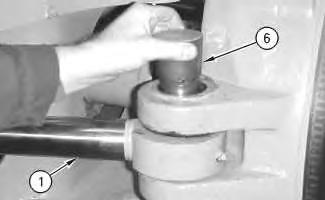
Illustration 19
Illustration 20
10. Install pin (6) into the rod end of steering cylinder (1). If necessary, position the grease hose assembly bracket. Install bolt (3) and the washer, and (4), into the pin at the rod end of the steering cylinder.
11. Tighten bolt (3). Strike the head of pin (6) with a suitable mallet. Tighten bolt (3). Continue to strike the pin and tighten the bolt until the torque is maintained.
12. If necessary, connect grease hose assembly (2).
13. Remove Tooling (D) from the front and rear of the machine.
14. Reset the front suspension. Refer to Operation and Maintenance Manual, "Suspension SystemCheck / Adjust".
15. Lubricate the steering cylinder bearings. Refer to Operation and Maintenance Manual, "Steering Cylinder Bearings - Lubricate".