

Product: ARTICULATED TRUCK
Model: 740B ARTICULATED TRUCK L4E
Configuration: 740B Articulated Truck L4E00001-UP (MACHINE) POWERED BY C15 Engine
Disassembly and Assembly
C15 and C18 Engines for Caterpillar Built Machines
Media Number -RENR8261-23
Alternator - Remove and Install
SMCS - 1405-010
Removal Procedure
Personal injury can result from failure to disconnect the battery.
First, disconnect the negative battery cable. Then, disconnect the positive battery cable.
A positive power lead cancause sparksif the battery is not disconnected. Sparks can possibly result in battery explosion or fire.
1. Disconnect the batteries.
2. Remove the alternator belt.
3. Place identification marks on all of the harnessassemblies.
i06791558
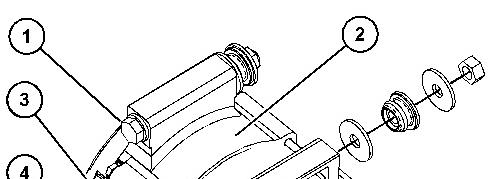
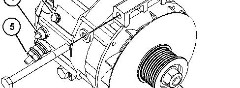
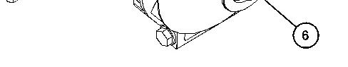
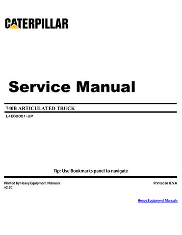
Illustration 1 g06116692
4. Disconnect the harness assemblies from terminal (4) and terminal (5).
5. Remove bolt (3) and the harness assembly from alternator (2).
6. Remove bolts (1). Remove alternator (2).
7. If necessary, remove nut (6) and remove the pulley from the alternator.
Installation Procedure
Illustration 2 g06116692
1. If necessary, install the pulley on alternator (2). Install nut (6). Tighten the nut to a torque of 127 ± 10 N·m (94 ± 7 lb ft).
2. Position alternator (2) on the alternator mounting bracket. Install bolts (1).
3. Connect the harness assembly to alternator (2) and install bolt (3). Tighten the bolt to a torque of 4.4 ± 1.0 N·m (39 ± 9 lb in).
4. Connect the harness assembly to terminal (5). Tighten the nut to a torque of 18 ± 2 N·m (13 ± 2 lb ft).
5. Connect the harness assembly to terminal (4).
6. Install the alternator belt.
7. Connect the batteries.
1993 - 2021 Caterpillar Inc.
Product: ARTICULATED TRUCK
Model: 740B ARTICULATED TRUCK L4E
Configuration: 740B Articulated Truck L4E00001-UP (MACHINE) POWERED BY C15 Engine
Disassembly and Assembly
C15 and C18 Engines for Caterpillar Built Machines
Media Number -RENR8261-23
Atmospheric Pressure Sensor - Remove and Install
SMCS - 1923-010
NOTICE
Keep all parts clean from contaminants.
Contaminants may cause rapid wear and shortened component life.
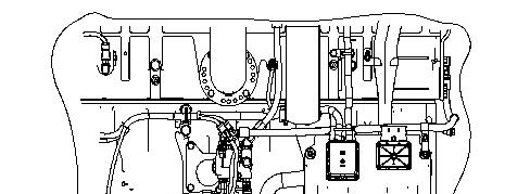
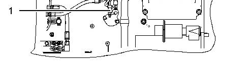
Illustration 1 g01116929
-01/08/2017
i02212192
(1) Atmospheric pressure sensor ... 10 ± 2 N·m (89 ± 18 lb in)
Copyright 1993 - 2021 Caterpillar Inc. All Rights Reserved. Private Network For SIS Licensees.
Mon Jun 7 21:12:38 UTC+0530 2021
Product: ARTICULATED TRUCK
Model: 740B ARTICULATED TRUCK L4E
Configuration: 740B Articulated Truck L4E00001-UP (MACHINE) POWERED BY C15 Engine
Disassembly and Assembly
C15 and C18 Engines for Caterpillar Built Machines Media Number -RENR8261-23
Bearing Clearance - Check
SMCS - 1203-535; 1219-535
Measurement Procedure
Table 1 Required Tools Tool
198-9142 Plastic Gauge (Green)
to 0.076 mm
to 0.003 inch)
Plastic Gauge (Red)
to 0.152 mm
to 0.006 inch)
Plastic Gauge (Blue)
to 0.229 mm (0.004 to 0.009 inch)
Plastic Gauge (Yellow) 0.230 to 0.510 mm (0.009 to 0.020 inch)
Note: Plastic gauge may not be necessary when the engine is in the chassis.
NOTICE
i05977048
Keep all parts clean from contaminants.
Contaminants may cause rapid wear and shortened component life.
Note: Cat does not recommend the checking of the actual bearing clearancesparticularly on small engines. Thisisbecause of the possibility of obtaining inaccurate results and the possibility of damaging the bearing or the journal surfaces. Each Cat engine bearing is quality checked for specific wall thickness.
Note: The measurements should be within specifications and the correct bearings should be used. If the crankshaft journals and the bores for the block and the rods were measured during disassembly, no further checks are necessary. However, if the technician still wants to measure the bearing clearances, Tooling (A) is an acceptable method. Tooling (A) is less accurate on journalswith small diametersif clearancesare less than 0.10 mm (0.004 inch).
NOTICE
Lead wire, shim stock or a dial bore gauge can damage the bearing surfaces.
The technician must be very careful to use Tooling (A) correctly. The following points must be remembered:
• Ensure that the backs of the bearings and the bores are clean and dry.
• Ensure that the bearing locking tabs are properly seated in the tab grooves.
• The crankshaft must be free of oil at the contact pointsof Tooling (A).
1. Put a piece of Tooling (A) on the crown of the bearing that is in the cap.
Note: Do not allow Tooling (A) to extend over the edge of the bearing.
2. Use the correct torque-turn specifications in order to install the bearing cap. Do not use an impact wrench. Be careful not to dislodge the bearing when the cap isinstalled.
Note: Do not turn the crankshaft when Tooling (A) is installed.
3. Carefully remove the cap, but do not remove Tooling (A). Measure the width of Tooling (A) while Tooling (A) is in the bearing cap or on the crankshaft journal. Refer to Illustration 1.
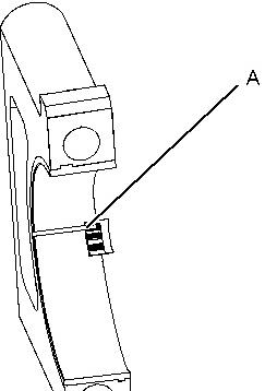

Illustration 1 g01152855
TypicalExample
4. Remove all of Tooling (A) before you install the bearing cap.
Note: When Tooling (A) is used, the readings can sometimes be unclear. For example, all parts of Tooling (A) are not the same width. Measure the major width in order to ensure that the parts are within the specification range. Refer to SpecificationsManual, "Connecting Rod Bearing Journal" and Specifications Manual, "Main Bearing Journal" for the correct clearances.
Copyright 1993 - 2021 Caterpillar Inc. All Rights Reserved. Private Network For SIS Licensees. Mon Jun 7 21:12:20 UTC+0530 2021
Product: ARTICULATED TRUCK
Model: 740B ARTICULATED TRUCK L4E
Configuration: 740B Articulated Truck L4E00001-UP (MACHINE) POWERED BY C15 Engine
Disassembly and Assembly
C15 and C18 Engines for Caterpillar Built Machines
Camshaft - Install
- 1210-012 Installation Procedure
Keep all parts clean from contaminants. Contaminants may cause rapid wear and shortened component life.