

Previous Screen
Product: ARTICULATED TRUCK
Model: 735C ARTICULATED TRUCK LFJ
Configuration: 735C Articulated Truck LFJ00001-UP (MACHINE) POWERED BY C15 Engine
Disassembly and Assembly
735C, 740C EJECTOR and 745C Articulated Trucks Power Train
Media Number -UENR4227-03 Publication Date -01/09/2015 Date Updated -03/01/2018
Axle Shaft - Remove and Install
SMCS - 3259-010
Removal Procedure NOTICE
Care must be taken to ensure that fluids are contained during performance of inspection, maintenance, testing, adjusting, and repair of the product. Be prepared to collect the fluid with suitable containers before opening any compartment or disassembling any component containing fluids.
Refer to Special Publication, NENG2500, "Dealer Service Tool Catalog" for tools and supplies suitable to collect and contain fluids on Cat® products.
Dispose of all fluids according to local regulations and mandates.
Left Side Axle Shaft
Table 1 Required Tools
A 1U-5832 Pry Bar 1
B 2P-8312 Retaining Ring Pliers 1
C 1U-8848 Axle Shaft Installer 1
NOTICE
Care must be taken to ensure that fluids are contained during performance of inspection, maintenance, testing, adjusting, and repair of the product. Be prepared to collect the fluid with suitable containers before opening any compartment or disassembling any component containing fluids.
Refer to Special Publication, NENG2500, "Dealer Service Tool Catalog" for tools and supplies suitable to collect and contain fluids on Cat® products.
Dispose of all fluids according to local regulations and mandates.
Note: Cleanliness is an important factor. Before the removal procedure, the exterior of the component should be thoroughly cleaned. This will help to prevent dirt from entering the internal mechanism.
Note: The following procedure must be used for the left side axle shaft because of the double splines on the inside of the axle shaft. The double splines will catch the differential lock if the normal removal procedure is used.
2
Illustration 3
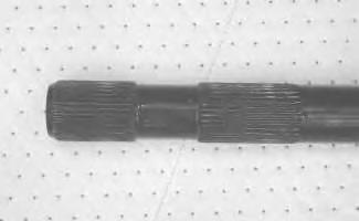
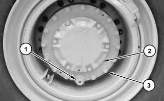
1. Move the wheel in order to position drain plug (1) at the bottom of cover (2). Remove the drain plug in order to allow the oil to drain into a suitable container.
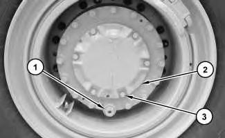
2. Remove bolts (3) and the washers. Remove cover (2) and O-ring seal (4) from the final drive.
4
5
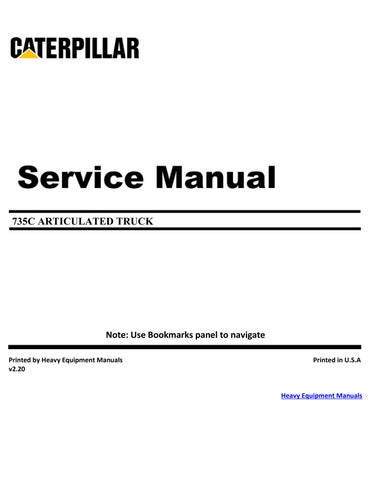
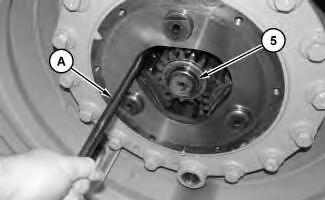
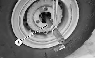
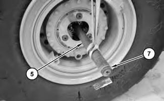
3. Use Tooling (A) in order to position axle shaft (5) so that sun gear (6) is flush with the final drive. Push back sun gear (6) in order to access retaining ring (7). Use Tooling (B) in order to remove retaining ring (7). Remove sun gear (6).
6
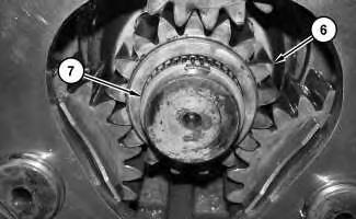
4. Use Tooling (B) in order to install retaining ring (7). Retaining ring (7) will be used to prevent damage to Tooling (C).
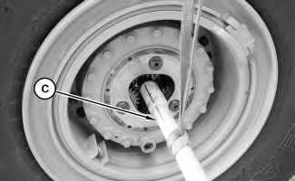
Illustration 7
8
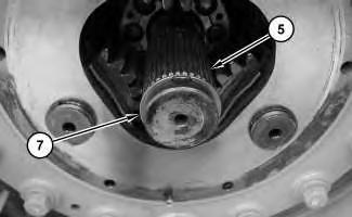
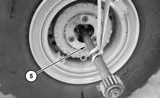
5. Attach a suitable lifting device and Tooling (C) to axle shaft (5). The weight of axle shaft (5) is approximately 35 kg (75 lb). Pull axle shaft (5) from the final drive enough to remove Tooling (C) and reposition the suitable lifting device . Remove axle shaft (5).
Right Side Axle Shaft
Table 2
9
1. Move the wheel in order to position drain plug (1) at the bottom of cover (2). Remove the drain plug in order to allow the oil to drain.
2. Remove bolts (3) and the washers. Remove cover (2) and O-ring seal (4) from the final drive.
3. Use Tooling (A) in order to position axle shaft (5) so that the sun gear is flush with final drive.
4. Attach a suitable lifting device to axle shaft (5). The weight of axle shaft (5) is approximately 35 kg (75 lb). Remove axle shaft (5).
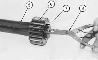
Illustration 13
g00846992
5. Use Tooling (B) in order to remove retaining ring (7) from axle shaft (5). Remove sun gear (6).
Installation Procedure
Note: Cleanliness is an important factor. Before the installation procedure, the exterior of the component should be thoroughly cleaned. This will help to prevent dirt from entering the internal mechanism.
Illustration 14
g01191336
Note: The same installation procedure will be used for the left axle shaft and the right axle shaft. The left side axle shaft has double splines for the differential lock that must be engaged.
15
16
1. Install retaining ring (7). Retaining ring (7) will be used to prevent damage to Tooling (C). Attach a suitable lifting device to axle shaft (5). The weight of axle shaft (5) is approximately 35 kg (75 lb). Install axle shaft (5). Use Tooling (C) in order to align the splines of axle shaft (5) into the differential .
17

18
2. Remove retaining ring (7). Install sun gear (6). Use a screwdriver in order to raise axle shaft (5) so that sun gear (6) can be fully installed without pushing axle shaft (5) further into the final drive. Install retaining ring (7).
19
20
3. Install O-ring seal (4). Install cover (2) for the final drive. Install bolts (3). Install drain plug (1) at the bottom of cover (2).
4. Check the oil level of the final drive. Add oil, if necessary. Refer to Operation and Maintenance Manual, "Differential and Final Drive Oil - Change". Copyright 1993 - 2025 Caterpillar Inc. All Rights Reserved.
Network For SIS Licensees. Tue Jun 17 16:09:16 UTC+0530 2025