

This is the sample of the manual click on the download link for complete manual
DOWNLOAD LINK
For some reason if link does not work download this pdf and then click

Product: ARTICULATED TRUCK
Model: 735 ARTICULATED TRUCK AWR
Configuration: 735 Articulated Truck AWR00001-UP (MACHINE) POWERED BY 3406E Engine
Disassembly and Assembly
3406E and 3456 Engines for Caterpillar Built Machines
Bearing Clearance - Check
SMCS - 1203-535; 1219-535
Measurement Procedure
Table 1 Required Tools
Tool
Plastic Gauge (Green)
to 0.076 mm
to 0.003 inch)
Plastic Gauge (Red)
to 0.152 mm (0.002 to 0.006 inch)
Plastic Gauge (Blue) 0.102 to 0.229 mm (0.004 to 0.009 inch)
Plastic Gauge (Yellow) 0.230 to 0.510 mm (0.009 to 0.020 inch)
Note: Plastic gauge may not be necessary when the engine is in the chassis.
NOTICE
i05977048
Keep all parts clean from contaminants.
Contaminants may cause rapid wear and shortened component life.
Note: Cat does not recommend the checking of the actual bearing clearances particularly on small engines. This is because of the possibility of obtaining inaccurate results and the possibility of damaging the bearing or the journal surfaces. Each Cat engine bearing is quality checked for specific wall thickness.
Note: The measurements should be within specifications and the correct bearings should be used. If the crankshaft journals and the bores for the block and the rods were measured during disassembly, no further checks are necessary. However, if the technician still wants to measure the bearing clearances, Tooling (A) is an acceptable method. Tooling (A) is less accurate on journals with small diameters if clearances are less than 0.10 mm (0.004 inch).
NOTICE
Lead wire, shim stock or a dial bore gauge can damage the bearing surfaces.
The technician must be very careful to use Tooling (A) correctly. The following points must be remembered:
• Ensure that the backs of the bearings and the bores are clean and dry.
• Ensure that the bearing locking tabs are properly seated in the tab grooves.
• The crankshaft must be free of oil at the contact points of Tooling (A).
1. Put a piece of Tooling (A) on the crown of the bearing that is in the cap.
Note: Do not allow Tooling (A) to extend over the edge of the bearing.
2. Use the correct torque-turn specifications in order to install the bearing cap. Do not use an impact wrench. Be careful not to dislodge the bearing when the cap is installed.
Note: Do not turn the crankshaft when Tooling (A) is installed.
3. Carefully remove the cap, but do not remove Tooling (A). Measure the width of Tooling (A) while Tooling (A) is in the bearing cap or on the crankshaft journal. Refer to Illustration 1.
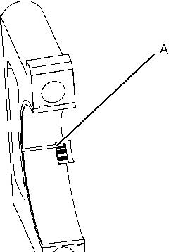

Illustration 1 g01152855
Typical Example
4. Remove all of Tooling (A) before you install the bearing cap.
Note: When Tooling (A) is used, the readings can sometimes be unclear. For example, all parts of Tooling (A) are not the same width. Measure the major width in order to ensure that the parts are within the specification range. Refer to Specifications Manual, "Connecting Rod Bearing Journal" and Specifications Manual, "Main Bearing Journal" for the correct clearances.
Copyright 1993 - 2024 Caterpillar Inc. All Rights Reserved. Private Network For SIS Licensees.
Wed Mar 27 11:12:40 UTC+0530 2024
Product: ARTICULATED TRUCK
Model: 735 ARTICULATED TRUCK AWR
Configuration: 735 Articulated Truck AWR00001-UP (MACHINE) POWERED BY 3406E Engine
Disassembly and Assembly
3406E and 3456 Engines for Caterpillar Built Machines
Camshaft - Install
Installation Procedure
all parts
1. Ensure that the camshaft and camshaft bearings are thoroughly clean. Lubricate the camshaft lobes with a 50/50 mixture of Tooling (K) and clean engine oil. Apply a thin coat of clean engine oil on the camshaft bearings.
1
2
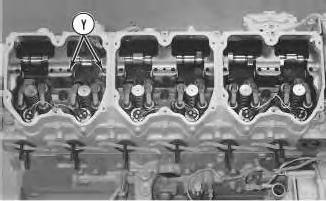
2. Install Tooling (A) on the cylinder head at Location (Y).
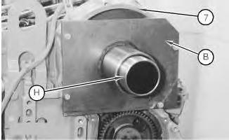
Illustration 3
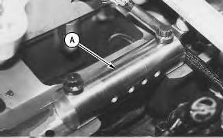
3. Install Tooling (B) on front housing (7). Do not tighten the bolts that hold Tooling (B) to front housing (7) at this time.
4. Use Tooling (H) to align Tooling (B) with the camshaft bearings. Tighten the bolts that hold Tooling (B) to front housing (7). Remove Tooling (H).
Note: Tooling (H) should move freely from the bore of Tooling (B).
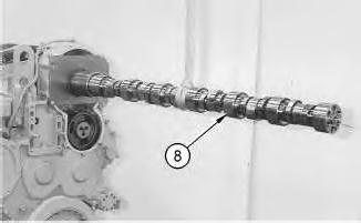
Illustration 4
5. Install Tooling (C) in the end of camshaft (8).
Note: Rotate the camshaft during installation. This will prevent the camshaft from binding in the camshaft bearings.
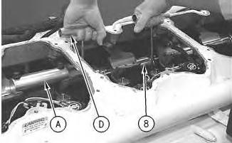
6. Use a suitable lifting device in order to position camshaft (8) into Tooling (B) and the cylinder head. The weight of the camshaft is approximately 39 kg (86 lb).
5
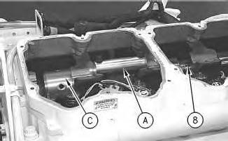
Illustration 6
Note: Tooling (C) must be removed before the camshaft can be completely installed in the cylinder head.
7. Remove the lifting device. Rotate the camshaft during installation. Use care not to allow the end of the camshaft and Tooling (C) to drop. Use Tooling (D) to assist in aligning camshaft (8) with the camshaft bearings.
8. Remove Tooling (C) and finish installing camshaft (8) in the bore.
9. Remove Tooling (A) and Tooling (B).
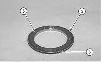
Illustration 7
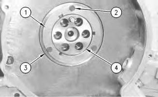
Illustration 8
10. Install O-ring seals (5) and (6) in seal assembly (3). Lubricate seal (6) with Tooling (K).
11. Install seal assembly (3). Position adapter (4). Ensure that the dowel in adapter (4) engages the hole in the camshaft.
12. Position thrust plate (1). Apply Tooling (J) to bolts (2). Hold thrust plate (1) in position and install bolts (2). Evenly tighten bolts (2) until seal assembly (3) and O-ring seal (5) are seated against the cylinder head.
Note: Be careful in order to ensure that O-ring seal (5) stays in the groove in seal assembly (3).
End By:
a. Install the rocker arms and the rocker shafts. Refer to Disassembly and Assembly, "Rocker Arm and Shaft - Install".
b. Install the camshaft gear. Refer to Disassembly and Assembly, "Camshaft Gear - Remove and Install".
Alternative Installation Procedure
Table 2
Part of 177-8003 Engine Tool Group
NOTICE
Keep all parts clean from contaminants.
Contaminants may cause rapid wear and shortened component life.
1. Ensure that the camshaft and camshaft bearings are thoroughly clean. Lubricate the camshaft lobes with a 50/50 mixture of Tooling (K) and clean engine oil. Apply a thin coat of clean engine oil on the camshaft bearings.
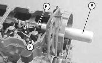
Illustration 9
g01043587
2. Install Tooling (F) on the front of camshaft (9) with Tooling (G).
3. Install Tooling (E).
4. Use two technicians to install the camshaft. Carefully slide camshaft (9) into the cylinder head from the rear of the engine. Keep the camshaft level while the camshaft is being installed in the cylinder head. The weight of the camshaft is approximately 39 kg (86 lb).
5. Remove Tooling (F).
10
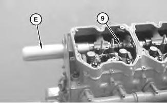
6. Install Tooling (F) on the end of the camshaft.
7. Use two technicians to install the camshaft. Carefully slide camshaft (9) into the cylinder head from the rear of the engine. Keep the camshaft level while the camshaft is being installed in the cylinder head. The weight of the camshaft is approximately 39 kg (86 lb).
8. Remove Tooling (F).
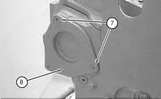
Illustration 11
9. Position cover (8) on the rear of the cylinder head. Install bolts (7).
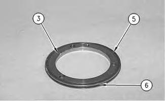
Illustration 12
g00576240
Illustration 13
g00576839
10. Install O-ring seals (5) and (6) in seal assembly (3). Lubricate seal (6) with Tooling (K).
11. Install seal assembly (3). Position adapter (4). Ensure that the dowel in adapter (4) engages the hole in the camshaft.
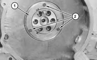
12. Position thrust plate (1). Apply Tooling (J) to bolts (2). Hold thrust plate (1) in position and install bolts (2). Evenly tighten bolts (2) until seal assembly (3) and O-ring seal (5) are seated against the cylinder head.
Note: Be careful in order to ensure that O-ring seal (5) stays in the groove in seal assembly (3).
End By:
a. Install the rocker arms and the rocker shafts. Refer to Disassembly and Assembly, "Rocker Arm and Shaft - Install".
b. Install the camshaft gear. Refer to Disassembly and Assembly, "Camshaft Gear - Remove and Install". Wed Mar 27 11:01:44 UTC+0530 2024
Product: ARTICULATED TRUCK
Model: 735 ARTICULATED TRUCK AWR
Configuration: 735 Articulated Truck AWR00001-UP (MACHINE) POWERED BY 3406E Engine
Disassembly and Assembly
3406E and 3456 Engines for Caterpillar Built Machines
Camshaft - Remove
- 1210-011
Removal Procedure
1
Start By:
a. Remove the camshaft gear. Refer to Disassembly and Assembly, "Camshaft Gear - Remove and Install".
b. Remove the rocker arms and the rocker shafts. Refer to Disassembly and Assembly, "Rocker Arm and Shaft - Remove".
NOTICE
Keep all parts clean from contaminants.
Contaminants may cause rapid wear and shortened component life.
NOTICE
Care must be taken to ensure that fluids are contained during performance of inspection, maintenance, testing, adjusting and repair of the product. Be prepared to collect the fluid with suitable containers before opening any compartment or disassembling any component containing fluids.
Refer to Special Publication, NENG2500, "Caterpillar Dealer Service Tool Catalog" for tools and supplies suitable to collect and contain fluids on Caterpillar products.
Dispose of all fluids according to local regulations and mandates.
1
NOTICE
Do not turn the crankshaft or the camshaft while the camshaft gear is removed. If the front gear group is not correctly timed during installation, interference can occur between the pistons and the valves, resulting in damage to the engine.
1. Remove bolts (2) and thrust plate (1).
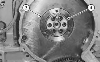
Illustration 2
g00576209
2. Remove seal assembly (3) and adapter (4).
Illustration 3
g00576240
3. Remove O-ring seals (5) and (6) from seal assembly (3).
NOTICE
Care must be used when removing the camshaft to not damage the highly finshed surfaces of both the camshaft and camshaft bearings
Illustration 4
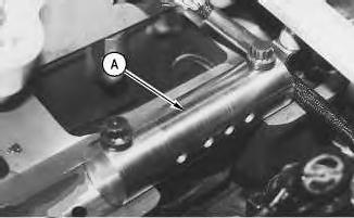
Illustration 5
4. Use the bolts for the rocker arm shaft assembly to install Tooling (A) at Location (Y).
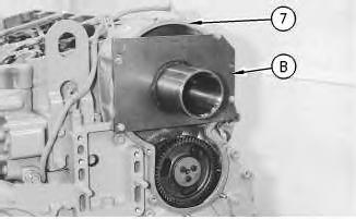
Illustration 6
5. Install Tooling (B) on front housing (7). Do not tighten the bolts for Tooling (B) at this time.
7
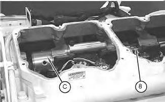
Note: It is necessary to install Tooling (C) on the camshaft. Tooling (C) will support the rear of camshaft (8) as the camshaft is moved out of the cylinder head and into Tooling (B).
6. Move camshaft (8) forward and install one Tooling (C) in the end of camshaft (8). Again, move the camshaft forward and install remaining Tooling (C) into the back of first Tooling (C).
7. Position camshaft (8) into the bore of Tooling (B). Tighten the bolts that hold Tooling (B) to the front housing.
8
Note: Avoid lifting camshaft (8) with Tooling (D). The camshaft should rest on Tooling (A). Lifting of the camshaft can cause misalignment as the camshaft is removed, resulting in damage to the camshaft bearings.
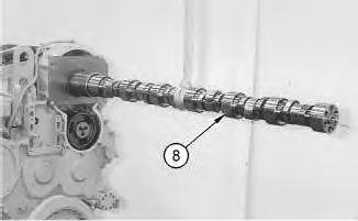
Illustration 9
8. Remove camshaft (8), as follows:
a. Use Tooling (D) to move camshaft (8) toward the front of the engine. Reposition Tooling (D), as needed.
b. Move camshaft (8) far enough out of the cylinder head in order to attach a suitable lifting device.
c. Keep the camshaft level while the camshaft is being removed from the cylinder head. The weight of the camshaft is approximately 39 kg (86 lb).
Alternative Removal Procedure
(1) Part of 177-8003 Engine Tool Group
Start By:
a. Remove the camshaft gear. Refer to Disassembly and Assembly, "Camshaft Gear - Remove and Install".
b. Remove the rocker arms and the rocker shafts. Refer to Disassembly and Assembly, "Rocker Arm and Shaft - Remove".
Note: This is an optional procedure to remove the camshaft. The preceding tool list shows the required tooling for removing the camshaft from the front of the engine or the rear of the engine.
NOTICE
Keep all parts clean from contaminants.
Contaminants may cause rapid wear and shortened component life.
NOTICE
Care must be taken to ensure that fluids are contained during performance of inspection, maintenance, testing, adjusting and repair of the product. Be prepared to collect the fluid with suitable containers before opening any compartment or disassembling any component containing fluids.
Refer to Special Publication, NENG2500, "Caterpillar Dealer Service Tool Catalog" for tools and supplies suitable to collect and contain fluids on Caterpillar products.
Dispose of all fluids according to local regulations and mandates.
10
NOTICE
Do not turn the crankshaft or the camshaft while the camshaft gear is removed. If the front gear group is not correctly timed during
installation, interference can occur between the pistons and the valves, resulting in damage to the engine.
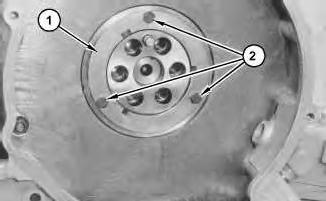
1. Remove bolts (2) and thrust plate (1).
Illustration 11
2. Remove seal assembly (3) and adapter (4).
Illustration 12
g00576240
3. Remove O-ring seals (5) and (6) from seal assembly (3).
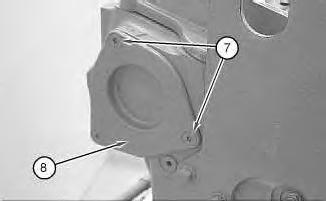
Illustration 13
4. Remove screws (7) and cover (8).
g01043575
NOTICE
Care must be used when removing the camshaft to not damage the highly finshed surfaces of both the camshaft and camshaft bearings
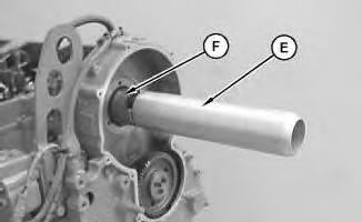
Illustration 14
g01024825
Note: Carefully align Tooling (F) with the end of the camshaft. If the adapter and the camshaft are not aligned, the camshaft may not be removed. The adapter and camshaft bearing will interfere.
5. To remove the camshaft from the rear of the engine, install Tooling (F) on the front of the camshaft with Tooling (G).
6. Install Tooling (E).
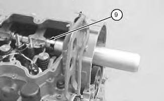
Illustration 15 g01043577
7. Carefully slide the camshaft to the rear of the engine for removal. Use two technicians to remove the camshaft. Keep the camshaft level while the camshaft is being removed from the cylinder head. The weight of the camshaft is approximately 39 kg (86 lb).
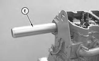
Illustration 16
g01024826
8. To remove the camshaft from the front of the engine, install Tooling (E) on the rear of the camshaft.
9. Carefully slide the camshaft to the front of the engine for removal. Use two technicians to remove the camshaft. Keep the camshaft level while the camshaft is being removed from the cylinder head. The weight of the camshaft is approximately 39 kg (86 lb). Copyright 1993 - 2024 Caterpillar Inc.
Mar 27 11:00:12 UTC+0530 2024
Product: ARTICULATED TRUCK
Model: 735 ARTICULATED TRUCK AWR
Configuration: 735 Articulated Truck AWR00001-UP (MACHINE) POWERED BY 3406E Engine
Disassembly and Assembly
3406E and 3456 Engines for Caterpillar Built Machines
Camshaft Bearings - Install
SMCS - 1211-012
Installation Procedure Table 1
This is the sample of the manual click on the download link for complete manual
DOWNLOAD LINK
For some reason if link does not work download this pdf and then click