Product: ARTICULATED TRUCK
Model: 730C ARTICULATED TRUCK LFF
Configuration: 730C Articulated Truck LFF00001-UP (MACHINE) POWERED BY C13 Engine
Operation and Maintenance Manual
730C Articulated Truck Media Number -SEBU8785-06
Foreword
Literature Information
s00037320
This manual should be stored in the operator's compartment in the literature holder or seat back literature storage area.
This manual contains safety information, operation instructions, transportation information, lubrication information and maintenance information.
Some photographs or illustrations in this publication show details or attachments that can be different from your machine. Guards and covers might have been removed for illustrative purposes.
Continuing improvement and advancement of product design might have caused changes to your machine which are not included in this publication. Read, study and keep this manual with the machine.
Whenever a question arises regarding your machine, or this publication, please consult your Cat dealer for the latest available information.
Safety
The safety section lists basic safety precautions. In addition, this section identifies the text and locations of warning signs and labels used on the machine.
Read and understand the basic precautions listed in the safety section before operating or performing lubrication, maintenance and repair on this machine.
Operation
The operation section is a reference for the new operator and a refresher for the experienced operator. This section includes a discussion of gauges, switches, machine controls, attachment controls, transportation and towing information.
Photographs and illustrations guide the operator through correct procedures of checking, starting, operating and stopping the machine.
Operating techniques outlined in this publication are basic. Skill and techniques develop as the operator gains knowledge of the machine and its capabilities.
Maintenance
The maintenance section is a guide to equipment care. The Maintenance Interval Schedule (MIS) lists the items to be maintained at a specific service interval. Items without specific intervals are listed under the "When Required" service interval. The Maintenance Interval Schedule lists the page number for the step-by-step instructions required to accomplish the scheduled maintenance. Use the Maintenance Interval Schedule as an index or "one safe source" for all maintenance procedures.
Maintenance Intervals
Use the service hour meter to determine servicing intervals. Calendar intervals shown (daily, weekly, monthly, etc.) can be used instead of service hour meter intervals if they provide more convenient servicing schedules and approximate the indicated service hour meter reading. Recommended service should always be performed at the interval that occurs first.
Under extremely severe, dusty or wet operating conditions, more frequent lubrication than is specified in the maintenance intervals chart might be necessary.
Perform service on items at multiples of the original requirement. For example, at every 500 service hours or 3 months, also service those items listed under every 250 service hours or monthly and every 10 service hours or daily.
California Proposition 65 Warning
Diesel engine exhaust and some of its constituents are known to the State of California to cause cancer, birth defects, and other reproductive harm.
Battery posts, terminals and related accessories contain lead and lead compounds. Wash hands after handling.
Certified Engine Maintenance
Proper maintenance and repair is essential to keep the engine and machine systems operating correctly. As the heavy duty off-road diesel engine owner, you are responsible for the performance of the required maintenance listed in the Owner Manual, Operation and Maintenance Manual, and Service Manual.
It is prohibited for any person engaged in the business of repairing, servicing, selling, leasing, or trading engines or machines to remove, alter, or render inoperative any emission related device or element of design installed on or in an engine or machine that is in compliance with the regulations (40 CFR Part 89). Certain elements of the machine and engine such as the exhaust system, fuel system, electrical system, intake air system and cooling system may be emission related and should not be altered unless approved by Caterpillar.
Machine Capacity
Additional attachments or modifications may exceed machine design capacity which can adversely affect performance characteristics. Included would be stability and system certifications such as brakes, steering, and rollover protective structures (ROPS). Contact your Cat dealer for further information.
Cat Product Identification Number
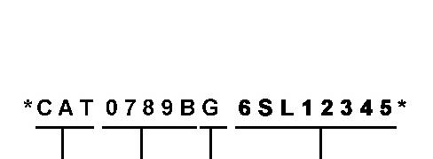
Effective First Quarter 2001 the Cat Product Identification Number (PIN) has changed from 8 to 17 characters. In an effort to provide uniform equipment identification, Caterpillar and other construction equipment manufacturers are moving to comply with the latest version of the product identification numbering standard. Non-road machine PINs are defined by ISO 10261. The new PIN format will apply to all Cat machines and generator sets. The PIN plates and frame marking will display the 17 character PIN. The new format will look like the following:
Illustration 1 g00751314
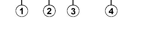
Where:
1. Caterpillar's World Manufacturing Code (characters 1-3)
DOWNLOAD LINK
For some reason if link does not work download this pdf and then click
2. Machine Descriptor (characters 4-8)
3. Check Character (character 9)
4. Machine Indicator Section (MIS) or Product Sequence Number (characters 10-17). These were previously referred to as the Serial Number.
Machines and generator sets produced before First Quarter 2001 will maintain their 8 character PIN format.
Components such as engines, transmissions, axles, etc. and work tools will continue to use an 8 character Serial Number (S/N). Copyright 1993 - 2025 Caterpillar Inc. All Rights Reserved. Private Network For SIS Licensees.
Product: ARTICULATED TRUCK
Model: 730C ARTICULATED TRUCK LFF
Configuration: 730C Articulated Truck LFF00001-UP (MACHINE) POWERED BY C13 Engine
Operation and Maintenance Manual
730C Articulated Truck
Media Number -SEBU8785-10
Date -01/06/2015 Date Updated -24/09/2020
Aftercooler Core - Inspect/Clean
SMCS - 1064-571
Personal injury can result from air pressure.
Personal injury can result without following proper procedure. When using pressure air, wear a protective face shield and protective clothing.
Maximum air pressure at the nozzle must be less than 205 kPa (30 psi) for cleaning purposes.
i05592910
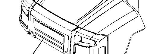
Illustration 1 g03486517
Raise the hood. Refer to Operation and Maintenance Manual, "Hood Control".
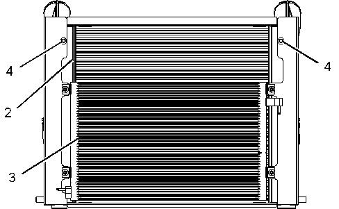
Illustration 2 g03550936
1. Remove four bolts from grill (1).
2. Remove grill in order to access the aftercooler core (2).
3. The air conditioner condenser (3) is hinged and can be lowered by removing the two bolts (4) to provide better access.
Inspect the aftercooler core and clean the aftercooler core. You can use compressed air, high -pressure water, or steam to remove dust and other debris from the aftercooler core. However, the use of compressed air is preferred.
4. Raise air conditioner condenser (3) and install tow bolts (4).
5. Install grill and tighten four bolts. Lower the hood. Copyright 1993 - 2025 Caterpillar Inc.
Rights Reserved.
Network For SIS Licensees. Sat Jan 11 01:48:40 UTC+0530 2025
Product: ARTICULATED TRUCK
Model: 730C ARTICULATED TRUCK LFF
Configuration: 730C Articulated Truck LFF00001-UP (MACHINE) POWERED BY C13 Engine
Operation and Maintenance Manual
730C Articulated Truck
Media Number -SEBU8785-10 Publication Date -01/06/2015 Date Updated -24/09/2020
Automatic Lubrication Filler Filter - Clean - Autolube - If Equipped
SMCS - 7540-070-HR
i06891205
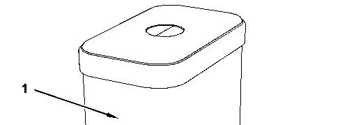
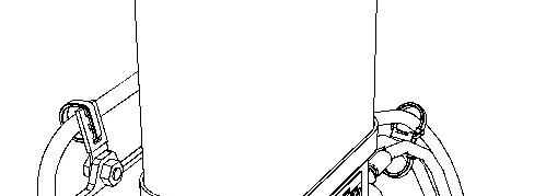
Illustration 1 g02494037
(1) Reservoir
(2) Dust Cap (3) Filler Tube Assembly
1. Remove dust cap (2) from reservoir (1).
2. Clean filler tube assembly (3) and the coupling on the filler tube assembly.
3. Remove filler tube assembly (3) and the coupling.
4. Remove the grease fitting from the filter and clean the filter.
5. Clean the filter with solvent and compressed air. Check the filter for cracks. If any cracks exist, replace the filter.
6. Replace the grease fitting in the filter.
7. Fill the filter with grease.
8. Install the filter.
9. Install the filter assembly onto filler tube assembly (3).
10. Install filler tube assembly (3) and dust cap (2).
Copyright 1993 - 2025 Caterpillar Inc. All Rights Reserved. Private Network For SIS Licensees. Sat Jan 11 01:48:53 UTC+0530 2025
Product: ARTICULATED TRUCK
Model: 730C ARTICULATED TRUCK LFF
Configuration: 730C Articulated Truck LFF00001-UP (MACHINE) POWERED BY C13 Engine
Operation and Maintenance Manual
730C Articulated Truck
Media Number -SEBU8785-10
-24/09/2020
Automatic Lubrication Grease Tank - Fill - If Equipped
SMCS - 7540-544-TNK
If the yellow LED on the signal lamp is illuminated, the minimum grease level in the reservoir has been reached.
• Ensure that the filler hose is primed with grease in order to prevent air from being introduced in the grease reservoir.
Illustration 1
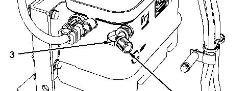
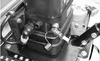
Location of the coupling on the lubrication pump
g01074471
• Remove the dust cap from the coupling for the filler.
• Carefully clean the coupling for the filler and the coupling on the filler hose. The coupler for the filler hose is supplied with each Autolube system.
• Fix the filler hose on the coupling for the filler.
i02695981
Illustration 2
g01076025
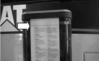
The maximum level mark on the lubrication pump
• Fill the reservoir up to the maximum level that is indicated on the reservoir.
• Remove the filler hose and fit the dust cap.
• Place the filler hose back in the hose's proper place in order to ensure that the coupling of the filler hose remains clean.
Note: Every 500 service hours replace the filter or every 500 service hours clean the filter for the filler on the lubrication pump. The filter is behind the connector on the reservoir.
Note: If the pumping action seems to go heavy, check the filter behind the coupling for the filler on the lubrication pump. Gently clean the filter or replace the filter. If the filter is damaged, the filter must be replaced.
Note: If too much grease is pumped into the reservoir, the surplus grease will exit the vent at the side of the lubrication pump. Any air that is introduced during the filling procedure will also escape via this route.
Note: Due to the slow capability of a hand held grease gun, the use of a grease gun is not recommended in order to fill the reservoir.
Periodic Checks
• Check the grease level in the reservoir. Refill the reservoir on time.
• Check that the signal lamp is functioning.
• Check that the duty cycle that is indicated on the signal lamp is correct for the operating conditions.
• Check the lubrication pump for damage and check the lubrication pump for leakage.
• Check the grease lines for damage and check the grease lines for leakage.
• Check the conditions of the grease points that are served by the system. Sufficient fresh grease should be present.
• Check the operation of the system. Perform a cycle test. Refer to System Operation, Testing and Adjusting, RENR6739 for more information.
• Clean the lubrication pump and clean the surroundings of the lubrication pump.
• Every 500 hours replace the filter or every 500 hours clean the filter.
Note: When you use high pressure water or high pressure air to clean the machine, do not spray directly onto the lubrication pump. Water or dirt may enter the lubrication pump through the dearating openings.
Note: The automatic lubrication system reduces the time and effort that is taken in order to grease the machine significantly. However, do not neglect grease points that are not served by the automatic lubrication system.
Grease Recommendations
Grease should not contain graphite or PTFE. Use the correct grease in the automatic lubrication system.
The use of a partially fluid grease that is above the maximum temperature that is indicated in Table 1 is not permitted. Use of a partially fluid grease that is above the maximum indicated temperature can lead to the following.
• Excessive component wear
• A reduction in the efficiency of the system
°C (176 °F) SYNTHETIC 2 0 °C (32 °F)
SYNTHETIC 0/1
Table 1
Product: ARTICULATED TRUCK
Model: 730C ARTICULATED TRUCK LFF
Configuration: 730C Articulated Truck LFF00001-UP (MACHINE) POWERED BY C13 Engine
Operation and Maintenance Manual
730C Articulated Truck
Media Number -SEBU8785-10
Axle Breathers - Clean/Replace
SMCS - 3278-070-BRE; 3278-510-BRE
1. Park the machine on a level surface. Move the parking brake control to the ENGAGED position and shut off the engine.
2. Install the Steering Frame Lock. Refer to Operation and Maintenance Manual, "Steering Frame Lock".
i05516435
Illustration 1
Illustration 2
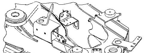
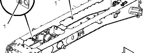
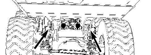
3. Remove breather (1) for each axle.
4. Wash each breather in clean, nonflammable solvent.
5. Shake each breather and allow each breather to dry.
6. Install each breather.
If any of the axle breathers are damaged, replace the damaged breather.
Remove the Steering Frame Lock after all the axle breathers are installed. Refer to Operation and Maintenance Manual, "Steering Frame Lock".
Product: ARTICULATED TRUCK
Model: 730C ARTICULATED TRUCK LFF
Configuration: 730C Articulated Truck LFF00001-UP (MACHINE) POWERED BY C13 Engine
Operation and Maintenance Manual
730C Articulated Truck
Media Number -SEBU8785-10
Backup Alarm - Test
SMCS - 7406-081
The backup alarm is on the rear of the machine.
Date -01/06/2015 Date Updated -24/09/2020
i02305428
Turn the engine start switch to the ON position in order to perform the test.
Apply the service brakes. Move the transmission control lever to the REVERSE position.
The backup alarm should start to sound immediately. The backup alarm will continue to sound until the transmission control lever is moved to the NEUTRAL position or to the FORWARD position.
Copyright 1993 - 2025 Caterpillar Inc. All Rights Reserved. Private Network For SIS Licensees. Sat Jan 11 01:49:45 UTC+0530 2025
Product: ARTICULATED TRUCK
Model: 730C ARTICULATED TRUCK LFF
Configuration: 730C Articulated Truck LFF00001-UP (MACHINE) POWERED BY C13 Engine
Operation and Maintenance Manual
730C Articulated Truck
Media Number -SEBU8785-10 Publication Date -01/06/2015 Date Updated -24/09/2020
Battery - Recycle
SMCS - 1401-561
i08232552
Always recycle a battery. Never discard a battery. Return used batteries to one of the following locations:
• A battery supplier
• An authorized battery collection facility
• A recycling facility Copyright 1993 - 2025 Caterpillar Inc. All Rights Reserved. Private Network For SIS Licensees. Sat Jan 11 01:49:57 UTC+0530 2025
Product: ARTICULATED TRUCK
Model: 730C ARTICULATED TRUCK LFF
Configuration: 730C Articulated Truck LFF00001-UP (MACHINE) POWERED BY C13 Engine
Operation and Maintenance Manual
730C Articulated Truck
Media Number -SEBU8785-10
Battery or Battery Cable - Inspect/Replace
SMCS - 1401-510; 1402-510
-24/09/2020
Inspect the condition of the cables to the batteries and inspect the condition of the batteries.
Note: When you replace the batteries, always use the same type of battery.
Use the following procedure in order to isolate the batteries if any repairs are necessary.
1. Turn the engine start switch to the OFF position. Turn all switches to the OFF position.
2. Turn the battery disconnect switch to the OFF position. Remove the key.
3. At the battery disconnect switch, disconnect the negative battery cable that is connected to the frame.
Note: Do not allow the disconnected battery cable to contact the disconnect switch.
4. Disconnect the negative battery cable from the terminals of the batteries.
5. Perform the necessary repairs. Replace the cables or the batteries, as needed.
6. Connect the negative battery cable to the terminals of the battery.
7. Connect the negative battery cable at the battery disconnect switch.
8. Install the key for the battery disconnect switch. Turn the key to the ON position.
Copyright 1993 - 2025 Caterpillar Inc. All Rights Reserved. Private Network For SIS Licensees. Sat Jan 11 01:50:15 UTC+0530 2025
i01951790
Product: ARTICULATED TRUCK
Model: 730C ARTICULATED TRUCK LFF
Configuration: 730C Articulated Truck LFF00001-UP (MACHINE) POWERED BY C13 Engine
Operation and Maintenance Manual
730C Articulated Truck
Media Number -SEBU8785-10
Belt - Inspect/Replace
SMCS - 1357-040; 1357-510; 1397-040; 1397-510
-24/09/2020
The engine is equipped with a serpentine belt that drives the alternator and the air conditioner.
Note: The engine is equipped with a belt tensioner that automatically adjusts the belt to the correct tension.
1. Park the machine on a level surface. Engage the parking brake. Shut off the engine.
2. Raise the hood. Refer to Operation and Maintenance Manual, "Hood Control".
Illustration 1 g06114636
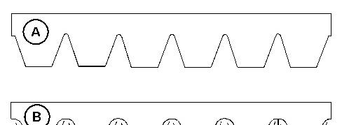
(A) New belt
(B) Worn belt
i06844307
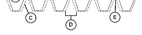
3. Inspect the condition of the serpentine belt. Over time the belt ribs will lose material (C). The space between the ribs will increase (D). The loss of material will cause the pulley sheave to contact the belt valley. The loss of material will lead to belt slippage and accelerated wear (E). Replace the belt if the belt is worn or frayed.
2
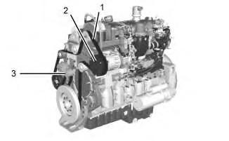
4. If belt (1) requires replacement, perform the following:
a. Loosen fasteners for belt guard , and remove belt guard (2).
b. Insert a square drive onto the belt tensioner (3). Turn clockwise to release the tension from the belt and remove the old belt.
c. Insert a square drive onto the belt tensioner (3) and turn clockwise. Install the new belt in the following order: drive pulley , air conditioning compressor pulley , alternator pulley, and belt tensioner .
d. Install belt guard and tighten fasteners.
5. Lower the hood. Refer to Operation and Maintenance Manual, "Hood Control".
Illustration
g02925498
Product: ARTICULATED TRUCK
Model: 730C ARTICULATED TRUCK LFF
Configuration: 730C Articulated Truck LFF00001-UP (MACHINE) POWERED BY C13 Engine
Operation and Maintenance Manual
730C Articulated Truck
Media Number -SEBU8785-10
Body Pivot Bearings - Lubricate
SMCS - 7258-086-BD; 7424-086
-24/09/2020
Park the machine on a level surface. Ensure that the parking brake is fully engaged. Lower the dump body and stop the engine.
Remove the caps and wipe the grease fittings before lubricant is applied. Install the caps after lubricant has been applied.
i04837616
There is a total of two grease fittings. One grease fitting on the end of each pivot pin. The fittings are located at the rear of the machine.
Lubricate the pivot bearings through the grease fittings. One or two shots will be required at each fitting if lubrication is carried out at the recommended interval.
Copyright 1993 - 2025 Caterpillar Inc. All Rights Reserved. Private Network For SIS Licensees. Sat Jan 11 01:50:39 UTC+0530 2025
Product: ARTICULATED TRUCK
Model: 730C ARTICULATED TRUCK LFF
Configuration: 730C Articulated Truck LFF00001-UP (MACHINE) POWERED BY C13 Engine
Operation and Maintenance Manual
730C Articulated Truck
Media Number -SEBU8785-10
Brake Accumulator (Service) - Check
SMCS - 4263-535
Personal injury or death can result from improper accumulator charging.
Dry Nitrogen is the only gas approved for use in the accumulator. Charging the accumulator with oxygen will cause an explosion. This danger will not happen if nitrogen cylinders with standard CGA (Compressed Gas Association, Inc.) Number 580 connections are used.
When ordering nitrogen gas, be sure that the cylinders are equipped with CGA Number 580 connections. Do not use color codes or other methods of identification to tell the difference between nitrogen and oxygen cylinders
Never use an adapter to connect your nitrogen charging group to a valve outlet used on both nitrogen, oxygen, or other gas cylinders. BE SURE YOU USE DRY NITROGEN (99.8% purity).
Refer to Systems Operation, Testing and Adjusting, "Brake Accumulator (Service) - Test and Charge" for more information.
Copyright 1993 - 2025 Caterpillar Inc. All Rights Reserved.
Private Network For SIS Licensees. Sat Jan 11 01:50:51 UTC+0530 2025
i02253515