Previous Screen
Product: EJECTOR TRUCK
Model: 730C2 EJ EJECTOR TRUCK 2L8
Configuration: 730C2 Ejector Articulated Truck 2L800001-UP (MACHINE) POWERED BY C13 Engine
Disassembly and Assembly
725C2, 730C2 Ejector Articulated Trucks - Machine Systems
Media
i05870513
Steering Cylinder - Remove and Install
SMCS - 4303-010
Removal Procedure
1
Start By:
a. Connect the steering frame lock.
b. Release the hydraulic system pressure.
Care must be taken to ensure that fluids are contained during performance of inspection, maintenance, testing, adjusting, and repair of the product. Be prepared to collect the fluid with suitable containers before opening any compartment or disassembling any component containing fluids.
Refer to Special Publication, NENG2500, "Dealer Service Tool Catalog" for tools and supplies suitable to collect and contain fluids on Cat products.
Dispose of all fluids according to local regulations and mandates.
1
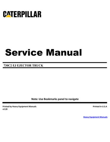
1. Use suitable cribbing in order to support front fender (1).
2. Remove bolts (2). Remove deflector (3).
Illustration
g01166659
Illustration 2
g01166664
3
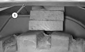
3. Remove bolts (4). Use two people in order to remove support assembly (5). The weight of support assembly (5) is approximately 29 kg (65 lb).
4
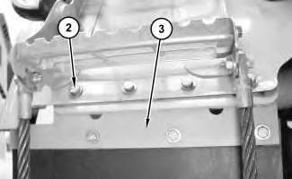
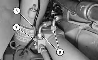
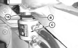
4. Disconnect grease hose assembly (6). Remove bolt (7). Disconnect hose assemblies (8).
5
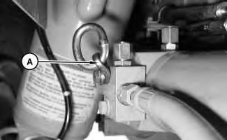
5. Install Tooling (A).
Illustration
g01166669
Illustration
g01166676
Illustration
g01166692
Illustration 6
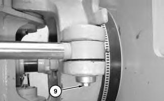
6. Remove bolt (9) and the washer.
Illustration 7
g01166704
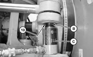
7. Use suitable cribbing, Tooling (B), and Tooling (C) in order to remove pin (10) (not shown).
Illustration 8
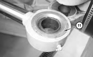
8. Remove face seals (11).
g01166707
g01166699
9
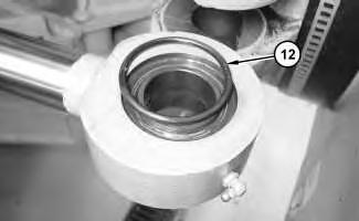
9. Remove O-ring seals (12).
Illustration 10
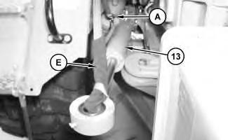
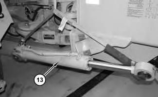
10. Attach a suitable lifting device and Tooling (E) to Tooling (A) and steering cylinder (13). The weight of steering cylinder (13) is approximately 50 kg (110 lb).
Illustration 11
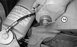
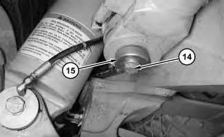
11. Remove bolt (14) and the washer.
Illustration
g01166709
g01166715
g01166722
Illustration 12
Typical Example
12. Place a suitable wedge between Tooling (C) and the frame of the machine in order to align Tooling (C) with pin (15). Use Tooling (B) and Tooling (C) in order to remove pin (15).
g01228830
Illustration 13
g01166730
13. Remove steering cylinder (13).
Illustration 14
g01166807
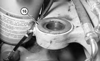
14. Remove face seals (16).
Illustration 15
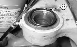
15. Remove O-ring seals (17).
g01166815
Illustration 16
g01166821
Illustration 17
Typical Example
g01228867
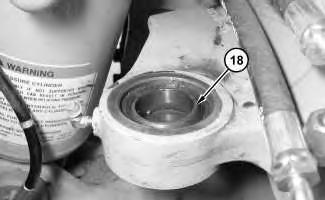
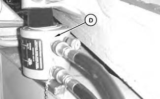
16. Place a suitable wedge between Tooling (D) and the frame of the machine in order to align Tooling (D) with bearing (18). Use Tooling (D) in order to remove bearing (18).
Disassembly and Assembly Information
Table 2
Required Tools
Cylinders equipped with lock valves can remain pressurized for very long periods of time, even with the hoses removed.
Failure to relieve pressure before removing a lock valve or disassembling a cylinder can result in personal injury or death.
Ensure all pressure is relieved before removing a lock valve or disassembling a cylinder.
Note: Cleanliness is an important factor. Before you begin the disassembly procedure, the exterior of the components should be thoroughly cleaned. This will help to prevent dirt from entering the internal mechanism. Precision components can be damaged by contaminants or by dirt. Perform disassembly procedures on a clean work surface. Keep components covered and protected at all times.
Note: Cleanliness is an important factor. Before assembly, all parts should be thoroughly cleaned in cleaning fluid. Allow the parts to air dry. Wiping cloths or rags should not be used to dry parts. Lint may be deposited on the parts which may cause later trouble. Inspect all parts. If any parts are worn or damaged, use new parts for replacement.
Illustration 18
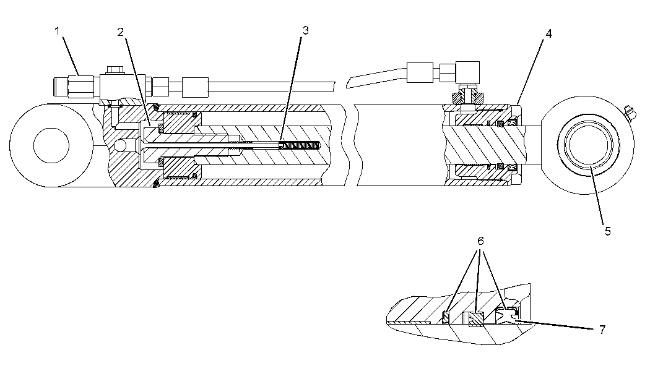
(1) Tighten the nut to a torque of 28 ± 5 N·m (21 ± 4 lb ft).
(2) Tighten the bolt to a torque of 1600 ± 200 N·m (1180 ± 150 lb ft). Replace a bolt that has been loosened or removed with a new bolt. Install the bolt with threads that are clean and free of lubricant.
(3) Tighten the locknut to a torque of 8 ± 1.5 N·m (71 ± 13 lb in).
(4) Apply Tooling (J) to the threads and tighten the head to a torque of 600 ± 130 N·m (440 ± 100 lb ft).
(5) Use Tooling (N) in order to remove the bearing. Use Tooling (F) in order to install the bearing.
(6) Lubricate the sealing lip lightly with the lubricant that is being sealed.
(7) Apply Tooling (H) to the wiper seal groove prior to installation.
Installation Procedure
Table 3
Required Tools
g01246202
Illustration 19
g01166821
Illustration 20
Typical Example
g01228867
1. Place a suitable wedge between Tooling (D) and the frame of the machine in order to align Tooling (D) with bearing (18). Use Tooling (D) in order to install bearing (18).
Illustration 21
2. Install O-ring seals (17).
Illustration 22
3. Install face seals (16).
Illustration 23
g01166715
4. Attach a suitable lifting device and Tooling (E) to Tooling (A) and steering cylinder (13). Position steering cylinder (13). The weight of steering cylinder (13) is approximately 50 kg (110 lb).
g01166815
g01166807
5. Install pin (not shown), washer (15) and bolt (14). Tighten bolt (14) to a torque of 240 ± 40 N·m (177 ± 30 lb ft). Strike the head of pin (15) with a suitable hammer and torque bolt (14) to a torque of 240 ± 40 N·m (177 ± 30 lb ft). Continue this procedure until bolt (14) maintains a torque of 240 ± 40 N·m (177 ± 30 lb ft). Recheck the torque of bolt (14) after the machine has been operated.
Illustration 24
g01166876
Illustration 25
g01166709
6. Install O-ring seals (12).
Illustration 26
g01166707
7. Install face seals (11).
8. Install pin (not shown), washer and bolt (9). Tighten bolt (9) to a torque of 240 ± 40 N·m (177 ± 30 lb ft). Strike the head of pin (10) with a suitable hammer and torque bolt (9) to a torque of 240 ± 40 N·m (177 ± 30 lb ft). Continue this procedure until bolt (9) maintains a torque of 240 ± 40 N·m (177 ± 30 lb ft). Recheck the torque of bolt (9) after the machine has been operated.
10. Connect hose assemblies (8). Install bolt (7). Connect grease hose assembly (6).
Illustration 27
g01166699
Illustration 28
g01166692
9. Remove Tooling (A).
Illustration 29
g01166676
11. Use two people in order to position support assembly (5). The weight of support assembly (5) is approximately 29 kg (65 lb). Install bolts (4).
31
12. Position deflector (3). Install bolts (2).
32
13. Remove the suitable cribbing from front fender (1).
End By:
a. Separate the steering frame lock.
Illustration 30
g01166669
Illustration
g01166664
Illustration
g01166659
Copyright 1993 - 2025 Caterpillar Inc.
Network For SIS Licensees. Tue Jun 17 16:05:27 UTC+0530 2025