

Note: Use Bookmarks panel to navigate

Product: ARTICULATED TRUCK
Model: 730C2 ARTICULATED TRUCK 2T4
Configuration: 730C2 Articulated Truck 2T400001-UP (MACHINE) POWERED BY C13 Engine
Disassembly and Assembly
730C2 and 725C2 Articulated Truck Power Train
Media Number -M0069866-04
Differential and Bevel Gear (Front and Rear) - Remove and Install
SMCS - 3256-010; 3258-010
Remove Procedure
Table 1 Required Tools
1U-9895 Crossblock
8B-7550 Push Puller Leg
1P-5546 Crossarm 1 5F-7366 Forcing Screw 1 3H-0465 Push-Puller Plate 4 1B-4207 Full Nut 2
B 439-3939 Link Bracket As 2
C 442-6518 Spanner Wrench As 1
D 1P-0520 Driver Group 2
E 463-3380 Lift Assembly 1
F - Loctite 5188 1
G 8T-5096 Indicator Group 1
Start By:
a. Remove the service brakes.
1
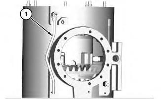
1. Remove tube assembly (1).
2
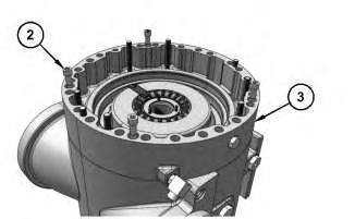
2. Remove bolts (2) from intermediate housing (3).
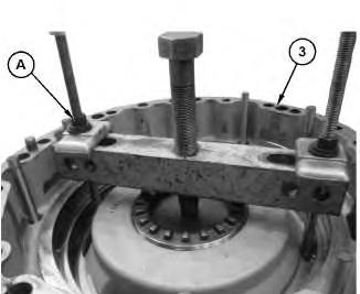
Illustration 3 g06125486
3. Use Tooling (A) to remove intermediate housing (3). Remove intermediate housing (3).
Note: Removal of intermediate housing (3) can be done by use of the threaded pusher holes. If not provided, place a plate on the differential case and use suitable puller by reaching through intermediate housing (3) openings.
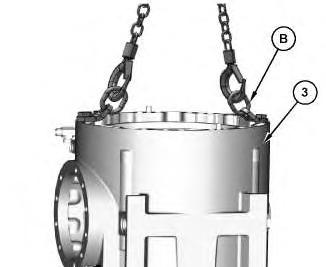
Illustration 4 g06128771
4. Attach Tooling (B) and a suitable lifting device to intermediate housing (3). The weight of intermediate housing (3) is approximately 45 kg (100 lb).
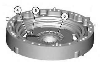
Illustration 5
5. Remove bolt (4) and bearing lock (5). Use Tooling (C) to remove adjusting nut (6). Remove adjusting nut (6).
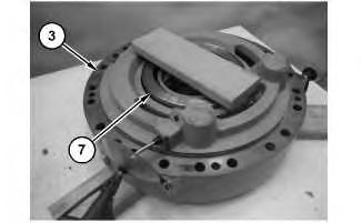
Illustration 6
Typical example
g06124706
6. Turn over intermediate housing (3). Apply air pressure to remove piston (7).
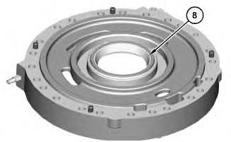
Illustration 7
7. Use Tooling (D) to remove bearing cup (8). Remove bearing cup (8).
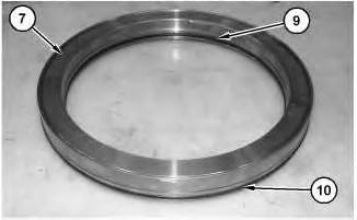
Illustration 8
8. Remove D-ring seals (9) and (10) from piston (7).
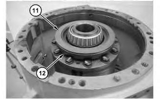
Illustration 9
9. Remove thrust washer (11) and bearing assembly (12).
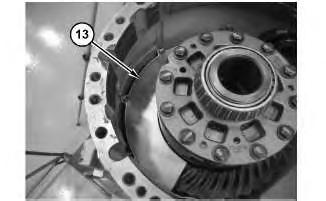
Illustration 10
10. Remove shroud (13).
11
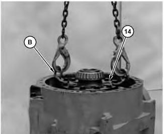
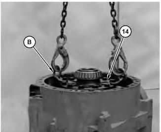
11. Attach Tooling (B) and a suitable lifting device to differential and bevel gear assembly (14). The weight of differential and bevel gear assembly (14) is approximately 77 kg (170 lb). Remove differential and bevel gear assembly (14).
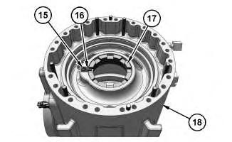
Illustration 12
g06124948
12. Attach a suitable lifting device to reposition differential housing (18). The weight of differential housing (18) is approximately 122 kg (270 lb).
13. Remove bolt (15) and bearing lock (16). Use Tooling (D) to remove adjusting nut (17). Remove adjusting nut (17).

13
14. Use Tooling (D) to remove bearing cup (19). Remove bearing cup (19) from differential housing (18).
Installation Procedure
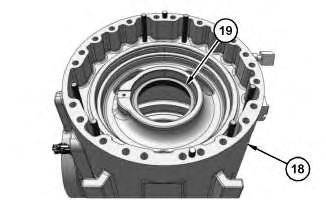
Illustration 14
g06124951
1. Use Tooling (D) to install bearing cup (19) into differential housing (18).
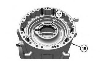
Illustration 15
g06127399
2. Install adjusting nut (17) into differential housing (18).
Note: Do not tighten adjusting nut (17) at this time. Do not install the bearing lock at this time.
3. Attach a suitable lifting device to differential housing (18). The weight of differential housing (18) is approximately 122 kg (270 lb).
16
4. Attach Tooling (B) and a suitable lifting device to differential and bevel gear assembly (14). The weight of differential and bevel gear assembly (14) is approximately 77 kg (170 lb). Install differential and bevel gear assembly (14).
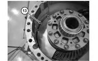
Illustration 17
5. Install shroud (13).
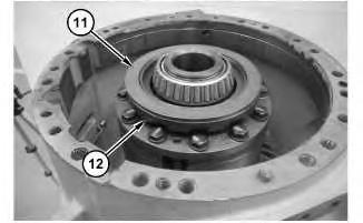
Illustration 18
g06124744
6. Install bearing assembly (12) and thrust washer (11).

Illustration 19
g06124735
7. Install D-ring seals (10) and (9) to piston (7).
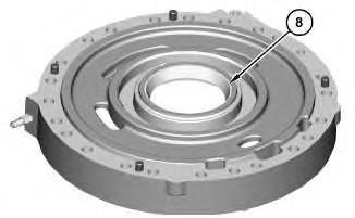
Illustration 20
g06124725
8. Use Tooling (D) to install bearing cup (8). Install bearing cup (8).