
730 ARTICULATED TRUCK
S/N B1M00001-UP

Product: ARTICULATED TRUCK
Model: 730 ARTICULATED TRUCK B1M
Configuration: 730 Articulated Truck B1M00001-UP (MACHINE) POWERED BY C11 Engine
Disassembly and Assembly
725, 730 and 730 Ejector
Articulated Trucks
Engine Supplement
Aftercooler - Remove and Install
SMCS - 1063-010
S/N - B1L1-UP
S/N - B1M1-UP
S/N - B1W1-UP
Removal Procedure
Start By:
A. Remove the cooling package. Refer to Disassembly and Assembly, "Cooling System Package (Radiator, Aftercooler, Refridgerant condensor) - Remove".
Personal injury or death can result from improper lifting or blocking.
When a hoist or jack is used to lift any part or component, stand clear of the area. Be sure the hoist or jack has the correct capacity to lift a component. Install blocks or stands before performance of any work under a heavy component.
Approximate weights of the components are shown. Clean all surfaces where parts are to be installed.
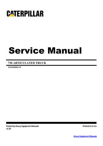
1
1. Remove bolts (1) and shroud assembly (2) .
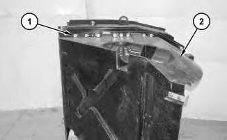
2
2. Remove bolts (3) and mount assembly (4). Remove bolts (5) and condenser (6) .
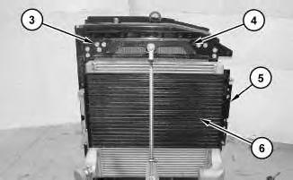
3
3. Attach a suitable lifting device to aftercooler (7). The weight of aftercooler (7) is approximately 29 kg (65 lb).
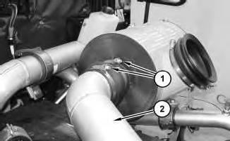
4. Remove bolts (8) and brackets (9) .
5. Remove aftercooler (7) .
Installation Procedure
Illustration 4
1. Attach a suitable lifting device to aftercooler (7) and position aftercooler (7). The weight of aftercooler (7) is approximately 29 kg (65 lb).
2. Position brackets (9) and install bolts (8) .
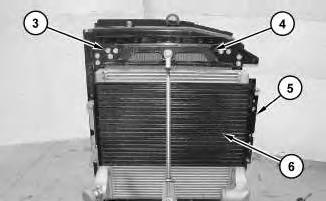
Illustration 5
3. Position condenser (6) and install bolts (5). Position mount assembly (4) and install bolts (3) .
6
4. Position shroud assembly (2) and install bolts (1) .
End By: Install the cooling package. Refer to Disassembly and Assembly, "Cooling System Package (Radiator, Aftercooler, Refridgerant condensor) - Install". Copyright 1993 - 2021 Caterpillar Inc.
Network For SIS Licensees.
This is the sample of the manual click on the download link for complete manual
Product: ARTICULATED TRUCK
Model: 730 ARTICULATED TRUCK B1M
Configuration: 730 Articulated Truck B1M00001-UP (MACHINE) POWERED BY C11 Engine
Disassembly and Assembly
725, 730 and 730 Ejector
Articulated Trucks
Engine Supplement
i02308858
Air Cleaner - Remove and Install
SMCS - 1051-010; 1054-010
Removal Procedure
1

2
2. Remove bolts (3) and (6). Remove air cleaner (5). If necessary, remove seal (4) .
Installation Procedure
3
1. Position air cleaner (5). Install bolts (3) and (6). Install seal (4) so that the seam in seal (4) is even with the rim of the tube all the way around the tube.
Illustration 4
Copyright 1993 - 2021 Caterpillar Inc. All Rights Reserved. Private Network For SIS Licensees. Fri May 7 23:48:53 UTC+0530 2021
Product: ARTICULATED TRUCK
Model: 730 ARTICULATED TRUCK B1M
Configuration: 730 Articulated Truck B1M00001-UP (MACHINE) POWERED BY C11 Engine
Disassembly and Assembly
725, 730 and 730 Ejector
Articulated Trucks
Engine Supplement
Alternator - Remove and Install
SMCS - 1405-010
S/N - B1L1-UP
S/N - B1M1-UP
S/N - B1W1-UP
Removal Procedure
1. Turn the battery disconnect switch to the OFF position. Refer to Operation and Maintenance Manual, "Battery Disconnect Switch".
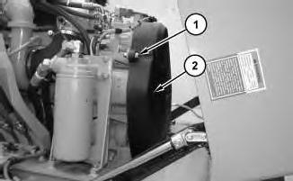
Illustration 1
2. Remove bolts (1) and guard (2) .
2
3. Remove belt (3) .
3
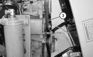
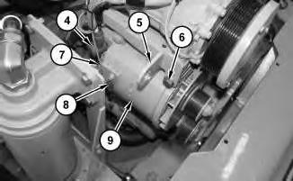
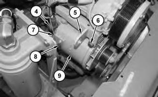
4. Disconnect harness assemblies (4), (7), and (8). Remove bolts (6), bracket (5), and alternator (9) .
Installation Procedure
4
1. Position alternator (9) and bracket (5). Install bolts (6). Connect harness assemblies (4), (7), and (8) .
5
6
3. Position guard (2) and install bolts (1). Tighten bolts (1) to a torque of 50 ± 10 N·m (37 ± 7 lb ft).
4. Turn the battery disconnect switch to the ON position. Refer to Operation and Maintenance Manual, "Battery Disconnect Switch".
This is the sample of the manual click on the download link for complete manual