
This is the sample of the manual click on the download link for complete manual
DOWNLOAD LINK
For some reason if link does not work download this pdf and then click

Product: FORWARDER
Model: 574 FORWARDER 1FM
Configuration: 574 Forwarder 1FM00001-UP (MACHINE) POWERED BY 3126 Engine
Disassembly and Assembly
554 Forwarder and 574 Forwarder Machine Systems
Air Conditioner - Assemble
SMCS - 7320-016
Assembly Procedure
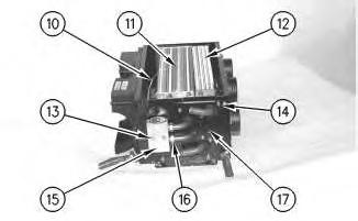
Illustration 1
g00632469
1. Install heater coil (12) and evaporator coil (11).
2. Install cover plate (17) and install three bolts (14).
3. Install valve block (15) and install two bolts (13).
4. Connect two tubes (16) to valve block (15). Install the O-ring seals.
5. Connect wire (10) to evaporator coil (11).
2
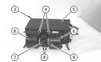
6. Install cover plate (5).
7. Install eight bolts (3) which hold cover plate (5) in place.
Note: Assemble the blower wheels to fan motor (9), if necessary. Fan motor (9) and the blower wheels are installed as a single unit.
8. Install fan motor (9) and mounting bracket (7).
9. Install four screws (8) which hold mounting bracket (7) in place.
10. Install two shrouds (6).
11. Install eight screws (4) which hold two shrouds (6) in place.
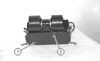
Illustration 3
12. Connect wire connector (2).
g00632397
13. Use a tie-wrap to secure the wire to housing (1).
End By:
a. Install the air conditioner. Refer to Disassembly and Assembly, "Air Conditioner - Install". Thu Mar 28 09:43:20 UTC+0530 2024
Product: FORWARDER
Model: 574 FORWARDER 1FM
Configuration: 574 Forwarder 1FM00001-UP (MACHINE) POWERED BY 3126 Engine
Disassembly and Assembly
554 Forwarder and 574 Forwarder Machine Systems
Air Conditioner - Disassemble
SMCS - 7320-015
Disassembly Procedure
Start By:
a. Remove the air conditioner. Refer to Disassembly and Assembly, "Air ConditionerRemove".
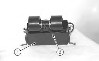
Illustration 1 g00632397
1. Disconnect wire connector (2).
2. Remove the tie-wrap which holds the wire to housing (1).
Illustration 2
3. Remove eight screws (4) which hold two shrouds (6) in place.
4. Remove two shrouds (6).
5. Remove four screws (8) which hold mounting bracket (7) in place.
6. Remove mounting bracket (7) and fan motor (9).
Note: Fan motor (9) and the blower wheels are removed as a single unit. The blower wheels may be disassembled from fan motor (9), if necessary.
7. Remove eight bolts (3) which hold cover plate (5) in place.
8. Remove cover plate (5).
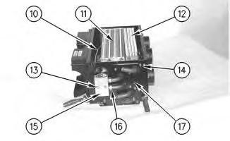
Illustration 3
g00632469
9. Disconnect wire (10) from evaporator coil (11).
10. Disconnect two tubes (16) from valve block (15). Remove the O-ring seals.
11. Remove two bolts (13) and remove valve block (15).
12. Remove three bolts (14) and remove cover plate (17).
13. Remove evaporator coil (11) and heater coil (12).
Product: FORWARDER
Model: 574 FORWARDER 1FM
Configuration: 574 Forwarder 1FM00001-UP (MACHINE) POWERED BY 3126 Engine
Disassembly and Assembly
554 Forwarder and 574 Forwarder Machine Systems
Air Conditioner - Install
SMCS - 7320-012
Installation Procedure
NOTICE
Care must be taken to ensure that fluids are contained during performance of inspection, maintenance, testing, adjusting, and repair of the product. Be prepared to collect the fluid with suitable containers before opening any compartment or disassembling any component containing fluids.
Refer to Special Publication, NENG2500, "Dealer Service Tool Catalog" for tools and supplies suitable to collect and contain fluids on Cat® products.
Dispose of all fluids according to local regulations and mandates.
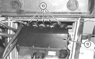
Illustration 1
1. Install air conditioner (11).
2. Connect five hoses (10) to air conditioner (11).
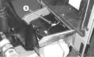
Illustration 2
3. Connect two wire connectors (9).
g00632135
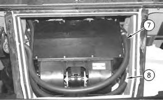
Illustration 3
4. Connect two refrigerant lines (8).
5. Connect two coolant hoses (7).
g00632126

4
6. Install four bolts (6) which hold the air conditioner in place.
Note: Install the drain lines for the air conditioner through the holes in the housing.
5
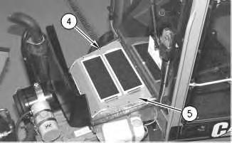
7. Install panel (5).
8. Install ten bolts (4).
6
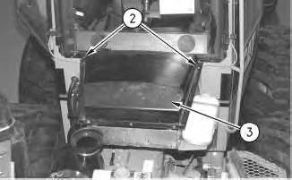
9. Close cover (3).
10. Install two bolts (2), the washers, and the nuts on cover (3).
11. Evacuate the air conditioning system and charge the air conditioning system.
Reference: Service Manual, SENR5664, "Air Conditioning and Heating Systems with R134A Refrigerant"
Reference: Special Publication, NEDG5065, "Air Conditioning Tools"
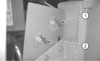
Illustration 7
12. Turn secondary disconnect switch (1) to the ON position.
13. Close the engine hood.
End By:
a. Separate the steering frame lock. Refer to Disassembly and Assembly, "Steering Frame Lock - Separate and Connect".
Copyright 1993 - 2024 Caterpillar Inc. All Rights Reserved. Private Network For SIS Licensees. Thu Mar 28 09:43:34 UTC+0530 2024
Product: FORWARDER
Model: 574 FORWARDER 1FM
Configuration: 574 Forwarder 1FM00001-UP (MACHINE) POWERED BY 3126 Engine
Disassembly and Assembly
554 Forwarder and 574 Forwarder Machine Systems
Air Conditioner - Remove
SMCS - 7320-011
Removal Procedure
Start By:
a. Connect the steering frame lock. Refer to Disassembly and Assembly, "Steering Frame Lock - Separate and Connect".
At operating temperature, the engine coolant is hot and under pressure.
Steam can cause personal injury.
Check the coolant level only after the engine has been stopped and the fill cap is cool enough to touch with your bare hand.
Remove the fill cap slowly to relieve pressure.
Cooling system conditioner contains alkali. Avoid contact with the skin and eyes to prevent personal injury.
Personal injury can result from contact with refrigerant.
Contact with refrigerant can cause frost bite. Keep face and hands away to help prevent injury.
Protective goggles must always be worn when refrigerant lines are opened, even if the gauges indicate the system is empty of refrigerant.
Always use precaution when a fitting is removed. Slowly loosen the fitting. If the system is still under pressure, release it slowly in a well ventilated area.
Personal injury or death can result from inhaling refrigerant through a lit cigarette.
Inhaling air conditioner refrigerant gas through a lit cigarette or other smoking method or inhaling fumes released from a flame contacting air conditioner refrigerant gas, can cause bodily harm or death.
Do not smoke when servicing air conditioners or wherever refrigerant gas may be present.
Use a certified recovery and recycling cart to properly remove the refrigerant from the air conditioning system.
NOTICE
Care must be taken to ensure that fluids are contained during performance of inspection, maintenance, testing, adjusting, and repair of the product. Be prepared to collect the fluid with suitable containers before opening any compartment or disassembling any component containing fluids.
Refer to Special Publication, NENG2500, "Dealer Service Tool Catalog" for tools and supplies suitable to collect and contain fluids on Cat® products.
Dispose of all fluids according to local regulations and mandates.
Note: Put identification on all lines, hoses, wires, and tubes for installation purposes. Use caps and plugs on all lines, hoses, and tubes in order to prevent fluid loss or contamination of the systems.
1. Open the engine hood.
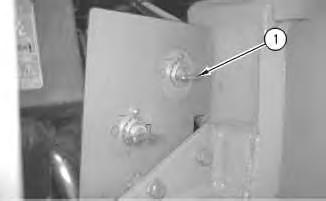
Illustration 1
g00611976
2. Turn secondary disconnect switch (1) to the OFF position.
3. Evacuate the air conditioning system.
Reference: Service Manual, SENR5664, "Air Conditioning and Heating Systems with R134A Refrigerant"
Reference: Special Publication, NEDG5065, "Air Conditioning Tools"
Illustration 2
g00632079
4. Remove two bolts (2), the washers, and the nuts from cover (3).
5. Open cover (3).
Illustration 3
6. Remove ten bolts (4).
7. Remove panel (5).
Illustration 4
8. Remove four bolts (6) which hold the air conditioner in place.
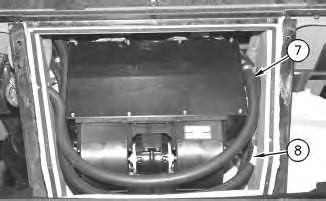
Illustration 5
9. Disconnect two coolant hoses (7).
10. Disconnect two refrigerant lines (8).
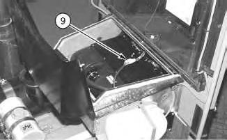
Illustration 6
11. Disconnect two wire connectors (9).
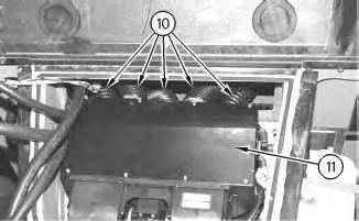
Illustration 7
12. Disconnect five hoses (10) from air conditioner (11).
13. Remove air conditioner (11).
Copyright 1993 - 2024 Caterpillar Inc. All Rights Reserved. Private Network For SIS Licensees. Thu Mar 28 09:42:50 UTC+0530 2024
Product: FORWARDER
Model: 574 FORWARDER 1FM
Configuration: 574 Forwarder 1FM00001-UP (MACHINE) POWERED BY 3126 Engine
Disassembly and Assembly
554 Forwarder and 574 Forwarder Machine Systems
Bank Valve (Eight) (Implement) - Assemble
SMCS - 5051-016-II
Assembly Procedure
Note: Cleanliness is an important factor. Before assembly, all parts should be thoroughly cleaned in cleaning fluid. Allow the parts to air dry. Wiping cloths or rags should not be used to dry parts. Lint may be deposited on the parts which may cause later trouble. Inspect all parts. If any parts are worn or damaged, use new parts for replacements.
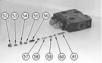
Illustration 1 g00597084
1. Install nozzle (61) in the valve segment. Install valve disc (60), spring (59), spring guide (58), and set screw (57) in the valve segment.
2. Install stud (56) in the valve segment. Tighten the stud to a torque of 2.5 N·m (22 lb in).
3. Install washer (55) and nut (54) on stud (56). Tighten the nut to a torque of 10 N·m (88 lb in).
4. Install washer (53) and nut (52) on stud (56). Tighten the nut to a torque of 10 N·m (88 lb in).
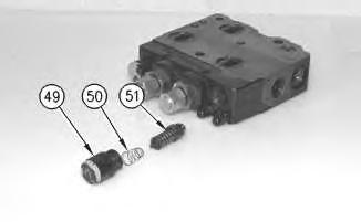
Illustration 2
g00597075
5. Install line relief valve (51) and spring (50) in the valve segment.
6. Install the O-ring on plug (49). Install plug (49) in the valve segment. Tighten the plug to a torque of 60 N·m (44 lb ft).
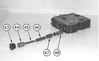
Illustration 3
g00597054
7. Install spool (48), sleeve (47), spring (46), spring (45), and piston (44) in the valve segment.
8. Install the O-ring on plug (43). Install plug (43) in the valve segment. Tighten the plug to a torque of 100 N·m (74 lb ft).
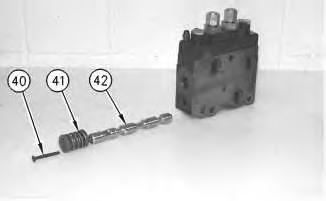
Illustration 4
g00596991
9. Install spool (42), spring (41), and spring (40) in the valve segment. Tighten the screw to a torque of 10 N·m (88 lb in).
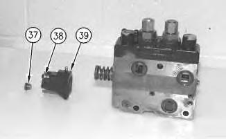
Illustration 5
g00596981
10. Place cap (39) in position on the valve segment. install two screws (38). Tighten the screws to a torque of 10 N·m (88 lb in).
11. Install the O-ring on plug (37). Install plug (37). Tighten the plug to a torque of 30 N·m (22 lb ft).
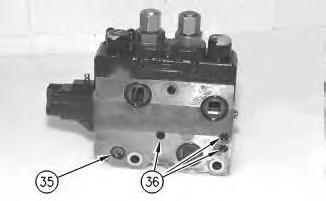
Illustration 6
g00596975
12. Install three O-rings (36). install O-ring (35).
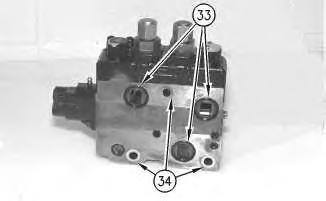
Illustration 7
g00596962
13. Install three spacers (34). Install three O-rings (33).
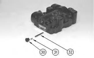
Illustration 8
g00596952
14. Install spool (32) and spring (31). Install the O-ring on the plug. Install plug (30). Tighten the plug to a torque of 30 N·m (22 lb ft).
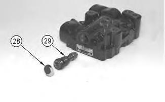
Illustration 9
g00596947
15. Install valve (29). Install the O-ring on the plug. Install plug (28). Tighten the plug to a torque of 30 N·m (22 lb ft).
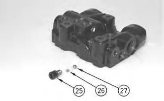
Illustration 10
g00596943
16. Install ball (27) and spring (26). Install the O-ring on plug (25). Install plug (25). Tighten the plug to a torque of 20 N·m (15 lb ft).
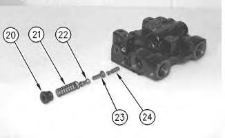
Illustration 11
g00596942
17. Install spool (24), poppet (23), poppet (22), and spring (21). Install the O-ring on plug (20). Install plug (20). Tighten the plug to a torque of 60 N·m (44 lb ft).
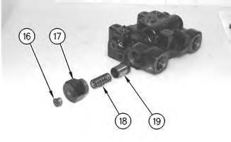
Illustration 12
g00596933
18. Install poppet (19) and spring (18). Install the O-ring on plug (17). Install plug (17). Tighten the plug to a torque of 60 N·m (44 lb ft).
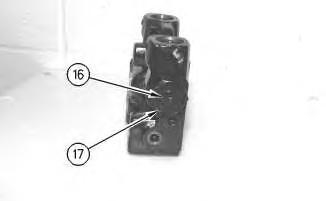
Illustration 13
g00596922
19. Install the O-ring on nut (17). Install nut (17). Tighten the nut to a torque of 60 N·m (44 lb ft). Install the O-ring on plug (16). Install plug (16). Tighten the plug to a torque of 30 N·m (22 lb ft).
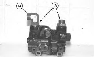
Illustration 14
g00596888
20. Install two adapters (15). Install elbow (14).
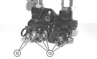
Illustration 15
21. Install five adapters (13). Install two pressure taps (12).
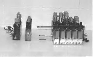
Illustration 16
22. Assemble the valve segments in the original order.
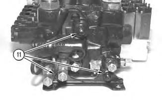
Illustration 17
g00596871
23. Install the mounting bracket. Install three nuts (11). Tighten the nuts to a torque of 60 N·m (44 lb ft).
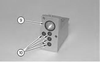
Illustration 18
g00596841
24. Install O-ring (9) on the back of the end cap. Install four O-rings (10) on the back of the end cap.
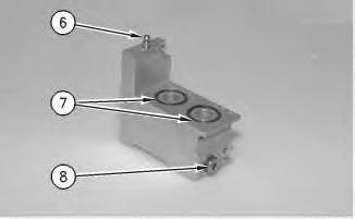
Illustration 19
g00596829
25. Install the orifice. Install the O-ring on plug (8). Install plug (8). Tighten the plug to a torque of 30 N·m (22 lb ft).
26. Install two O-rings (7). Install air purge screw (6).
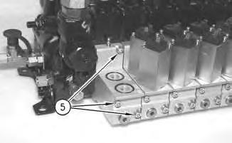
Illustration 20
g00596821
27. Place the end cap in position on the valve segment. Install three bolts (5) and the washers. Tighten the bolts to a torque of 10 N·m (88 lb in).
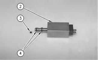
Illustration 21 g00596697
28. Install O-rings (4) on solenoid (2). Install orifice (3) in solenoid (2).
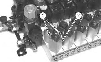
Illustration 22 g00596693
29. Place solenoid (2) in position on the valve segment. Install two screws (1) and the lock washers in solenoid (2). Tighten the screws to a torque of 3 N·m (26 lb in).
End By:
a. Install the implement control valve on the machine. Refer to Disassembly and Assembly, "Control Valve (Implement) - Install".
1993 - 2024 Caterpillar Inc.
This is the sample of the manual click on the download link for complete manual
DOWNLOAD LINK
For some reason if link does not work download this pdf and then click