


This is the sample of the manual click on the download link for complete manual
DOWNLOAD LINK
For some reason if link does not work download this pdf and then click

Product: WHEEL FELLER BUNCHER
Model: 563D WHEEL FELLER BUNCHER D63
Configuration: 563D WHEEL FELLER BUNCHER D6300001-UP (MACHINE) POWERED BY C7.1 ENGINE
Disassembly and Assembly
C7.1 Engines for Caterpillar Built Machines
Media Number -UENR4468-14
Publication Date -01/06/2015
Date Updated -19/02/2018
i05019069
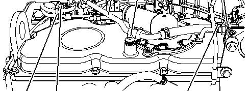
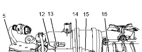
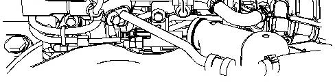
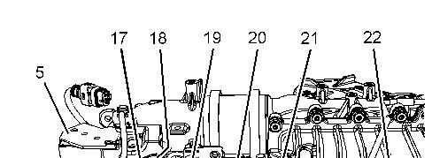
Pressure Sensor (Cooled Exhaust Gas) - Remove and Install -
Differential Pressure Sensor and Absolute Pressure Sensor
SMCS
Removal Procedure
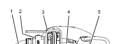
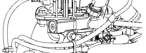

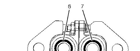
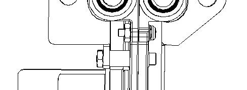

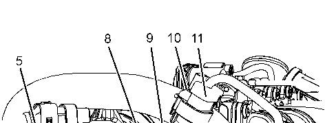
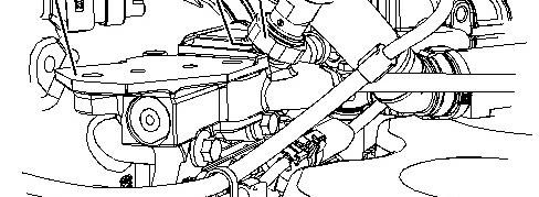

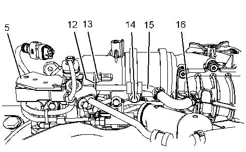
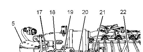

Installation Procedure
NOTICE
Ensure that wiring harness are correctly routed and the cable straps are not over tightened. Over tightening of the cable straps will damage the wiring harness convoluting.
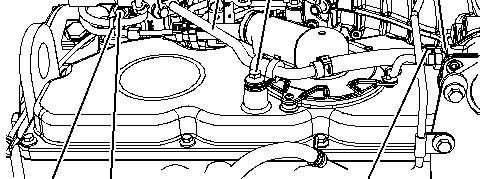

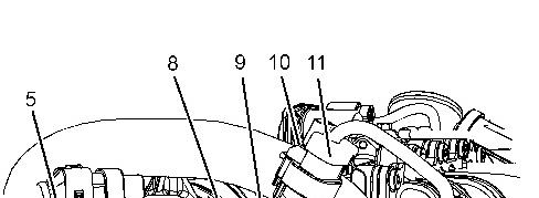
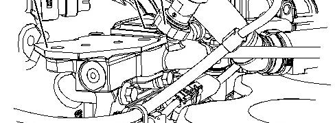

Note:
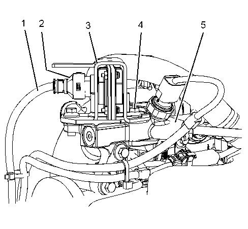

Note:
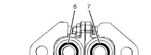
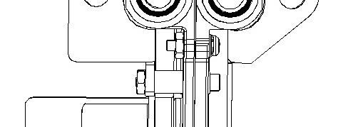
Ensure that the differential pressure sensor is correctly orientated on the manifold.

Product: WHEEL FELLER BUNCHER
Model: 563D WHEEL FELLER BUNCHER D63
Configuration: 563D WHEEL FELLER BUNCHER D6300001-UP (MACHINE) POWERED BY C7.1 ENGINE
Disassembly and Assembly
C7.1 Engines for Caterpillar Built Machines
Crankshaft Front Seal - Remove and Install
SMCS - 1160-010
Removal Procedure
Table 1
Required Tools
Start By:
a. Remove the crankshaft vibration damper and pulley.
NOTICE
Keep all parts clean from contaminants.
Contaminants may cause rapid wear and shortened component life.
i06799526
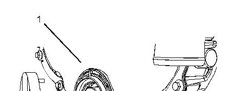
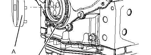

Illustration 1 g03417118
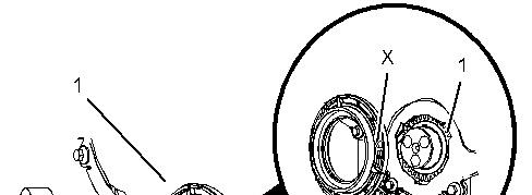
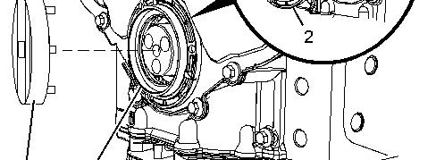
1. Position Tooling (A) onto crankshaft front seal (2).
2. Turn Tooling (A) in a counterclockwise direction and remove crankshaft front seal (2) from front cover (1).
Installation Procedure
1. Ensure that the front cover is clean and free from damage.

2 g03417120
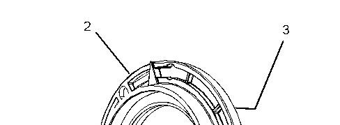
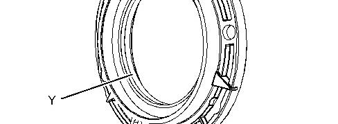

Illustration 3 g03453516
2. Apply Tooling (B) to static twin dead seal (3) (not shown) to a new crankshaft front seal (2). Ensure that none of Tooling (B) contaminates the crankshaft front seal in Position (Y).
3. Correctly position a new crankshaft front seal (2) in Position (X) onto front cover (1).
4. Position Tooling (A) onto crankshaft front seal (2).
5. Use Tooling (A) to turn crankshaft front seal (2) in a clockwise direction.
6. If a torque that is greater than 50 N·m (37 lb ft) is necessary to install crankshaft front seal (2), remove crankshaft front seal (2). Inspect crankshaft front seal (2) and front cover (1) for faults or damage.
7. If necessary, repeat Step 2 through Step 6 to install crankshaft front seal (2).
End By:
a. Install the crankshaft vibration damper and pulley.
Product: WHEEL FELLER BUNCHER
Model: 563D WHEEL FELLER BUNCHER D63
Configuration: 563D WHEEL FELLER BUNCHER D6300001-UP (MACHINE) POWERED BY C7.1 ENGINE
Disassembly and Assembly
C7.1 Engines for Caterpillar Built Machines
Media Number -UENR4468-14
Publication Date -01/06/2015
Date Updated -19/02/2018
Crankshaft Front Seal - Remove and Install - Crankshaft Front Seal for Heavy Duty Front Cover
SMCS - 1160-010
Removal Procedure Table 1 Required Tools
A 278-2636 Front Oil Seal Removal Tool 1
Start By:
a. Remove the crankshaft pulley. Refer to Disassembly and Assembly, "Vibration Damper and Pulley - Remove" for the correct procedure.
NOTICE
Keep all parts clean from contaminants.
Contaminants may cause rapid wear and shortened component life.
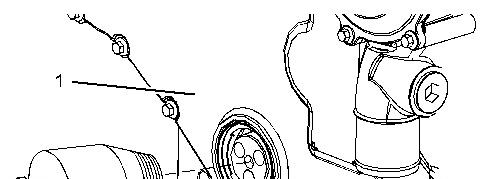
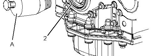

Illustration 1 g02048634
1. Position Tooling (A) on the nose of the crankshaft. Screw Tooling (A) into crankshaft front seal (2).
Note: Do not damage the edge of the front cover for the crankshaft front seal.
2. Screw the bolt into Tooling (A) in order to remove crankshaft front seal (2) from front cover (1).
Installation Procedure
2
NOTICE
Keep all parts clean from contaminants.
Contaminants may cause rapid wear and shortened component life.
1. Ensure that the bore for the crankshaft front oil seal in the front cover is clean and free from damage.
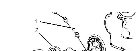
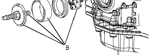

Illustration 2 g03417117
2. Assemble Tooling (B).
3. Correctly position a new crankshaft front seal (2) to front cover (1).
Note: If the crankshaft front seal is supplied with a sleeve, remove the sleeve from the crankshaft front seal before installation.
4. Use Tooling (B) to install crankshaft front seal (2) to front cover (1). Ensure that the front face of the crankshaft front seal is installed to a depth of 6.5 ± 0.2 mm (0.256 ± 0.008 inch).
5. Remove Tooling (B) from the crankshaft.
End By:
a. Install the crankshaft pulley. Refer to Disassembly and Assembly, "Vibration Damper and Pulley - Install" for the correct procedure.
Copyright 1993 - 2024 Caterpillar Inc. All Rights Reserved. Private Network For SIS Licensees.
Fri May 31 11:48:41 UTC+0530 2024
Product: WHEEL FELLER BUNCHER
Model: 563D WHEEL FELLER BUNCHER D63
Configuration: 563D WHEEL FELLER BUNCHER D6300001-UP (MACHINE) POWERED BY C7.1 ENGINE
Disassembly and Assembly
C7.1 Engines for Caterpillar Built Machines
Media Number -UENR4468-14
Vibration Damper and Pulley - Install
SMCS - 1205-012
Installation Procedure
Table 1
Required Tools
Keep all parts clean from contaminants.
Contaminants may cause rapid wear and shortened component life.
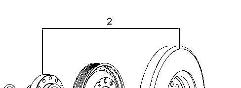
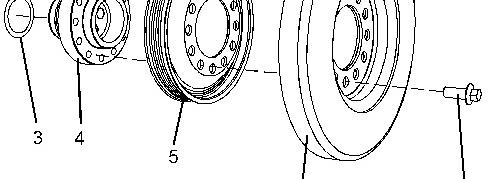

Illustration 1 g02368018
1. Ensure that the crankshaft adapter and the front of the crankshaft are clean and free from damage.
2. Inspect vibration damper (6) for damage. If necessary, replace the vibration damper.
3. If necessary, follow Step 3.a through Step 3.f in order to install vibration damper, crankshaft pulley to crankshaft adapter.
a. Place crankshaft adapter (4) onto a suitable support.
b. Install Tooling (D) crankshaft adapter (4) .
c. Install crankshaft pulley (5) and vibration damper (6) over Tooling (D) .
d. Install bolts (7) to the crankshaft pulley assembly.
Note: Evenly space bolts (7) around the crankshaft pulley assembly.
e. Remove Tooling (D) .
f. Tighten bolts (7) to a torque of 115 N·m (85 lb ft).
4. If necessary, install friction shim (3) . Follow Step 4.a through Step 4.b in order to install friction shim (3) .
a. Install friction shim (3) .
b. Install a new front seal to the front cover. Refer to Disassembly and Assembly, "Crankshaft Front Seal - Remove and Install" for the correct procedure.
5. Install Tooling (A) to the crankshaft.
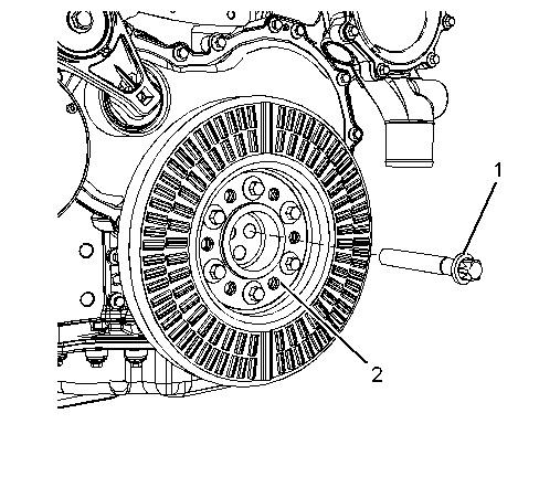
Illustration 2 g02368017
6. Install crankshaft pulley assembly (2) onto the crankshaft.
7. Install one Torx screws (1) to crankshaft pulley assembly (2) hand tighten.
8. Remove Tooling (A) .
9. Install remaining Torx screws (1) to crankshaft pulley assembly (2) .
10. Use a suitable tool in order to prevent the crankshaft from rotating. Tighten Torx screws (1) to a torque of 40 N·m (29 lb ft).
11. Use Tooling (B) and Tooling (C) to turn Torx screws (1) through an additional 120 degrees.
End By: Install the alternator belt. Refer to Disassembly and Assembly, "Alternator BeltRemove and Install" for the correct procedure.
Product: WHEEL FELLER BUNCHER
Model: 563D WHEEL FELLER BUNCHER D63
Configuration: 563D WHEEL FELLER BUNCHER D6300001-UP (MACHINE) POWERED BY C7.1 ENGINE
Disassembly and Assembly
C7.1 Engines for Caterpillar Built Machines
Media Number -UENR4468-14 Publication Date -01/06/2015 Date Updated -19/02/2018
Vibration Damper and Pulley - Remove
SMCS - 1205-011
Removal Procedure
Table 1
Required Tools
Start By:
A. Remove the alternator belt. Refer to Disassembly and Assembly, "Alternator Belt - Remove and Install" for the correct procedure.
Note: The weight of the assembly of the crankshaft pulley, the vibration damper, and the crankshaft adapter is approximately 22 kg (48 lb).
This is the sample of the manual click on the download link for complete manual
DOWNLOAD LINK
For some reason if link does not work download this pdf and then click