DOWNLOAD LINK
For some reason if link does not work download this pdf and then click
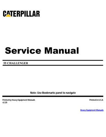
2. Loosen four hose clamps (4) on two hoses (3) .
2
3
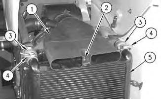
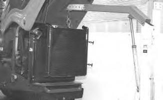
3. Install Tool (A) and Tooling (B) to the aftercooler.
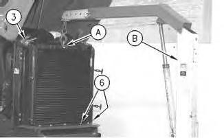
4. Remove bolts (6) in front of the aftercooler and behind each side of the aftercooler.
5. Remove the aftercooler from hoses (3) .
4
Illustration
g00557076
Illustration
g00557133
Illustration
g00589295
6. Remove the aftercooler. The weight of the aftercooler is 29 kg (63.9 lb).
Installation Procedure
Illustration 5
g00589295
1. Use Tool (A) and Tooling (B) to install the aftercooler. The weight of the aftercooler is 29 kg (63.9 lb).
Illustration 6
g00557076
Illustration 7
g00557133
2. Install the aftercooler to hoses (3) .
3. Install bolts (6) in front of the aftercooler behind each side of the aftercooler.
Illustration 8
4. Tighten four hose clamps (4) on two hoses (3) .
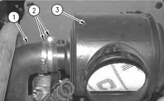
5. Install air intake duct (1) on aftercooler (5) .
6. Install bolt (2) and the washer.
End By: Install the refrigerant condenser and the fuel cooler. Refer to Disassembly and Assembly, "Refrigerant Condenser and Fuel Cooler - Remove and Install".
Product: CHALLENGER
Model: 55 CHALLENGER 6NN
Configuration: Challenger 55 Agricultural Tractor 60 in (1524 mm) Base Gauge 6NN00001-UP (MACHINE) POWERED BY 3126 Engine
Disassembly and Assembly
3116 Engine for Challenger 35, and Challenger 45 Agricultural Tractors and 3126 Engine for Challenger 55 Agricultural Tractor Engine Supplement Media Number -RENR1788-00
-09/10/2001
Air Cleaner - Remove and Install
SMCS - 1051-010; 1054-010
Removal Procedure
Start By:
i01069438
A. Remove the precleaner. Refer to Disassembly and Assembly, "Precleaner - Remove and Install".
Illustration 1 g00560044
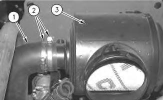
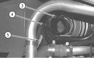
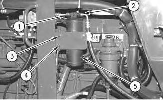
1. Loosen two hose clamps (2) and slide air inlet hose (1) off air cleaner (3) .
2
2. Disconnect quick coupler (5) from air filter vacuum switch (4) of air cleaner (3) .
3
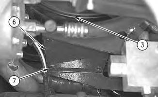
3. Remove four bolts (7) and the four washers from the bottom of bracket (6) .
4. Remove air cleaner (3) .
Installation Procedure
4
Illustration
g00560045
Illustration
g00560050
Illustration
g00560050
1. Position air cleaner (3) on bracket (6) .
2. Install four bolts (7) and the four washers from the bottom of the bracket.
5
3. Connect quick coupler (5) for air filter vacuum switch (4) on air cleaner (3) .
6
4. Slide air inlet hose (1) on air cleaner (3) and tighten two hose clamps (2) . End By: Install the precleaner. Refer to Disassembly and Assembly, "Precleaner - Remove and Install". Copyright 1993 - 2024 Caterpillar Inc.
Rights Reserved.
Network For SIS Licensees. Thu Apr 18 01:37:52 UTC+0530 2024
Illustration
g00560045
Illustration
g00560044
Product: CHALLENGER
Model: 55 CHALLENGER 6NN
Configuration: Challenger 55 Agricultural Tractor
Disassembly and Assembly
3116 Engine for Challenger 35, and Challenger 45 Agricultural Tractors and 3126 Engine for Challenger 55 Agricultural Tractor Engine Supplement
Air Conditioner Receiver/Dryer - Remove and Install
SMCS - 7322-010
Removal Procedure
Hot engine components can cause injury from burns. Before performing maintenance on the engine, allow the engine and the components to cool.
Personal injury can result from contact with refrigerant.
Contact with refrigerant can cause frost bite. Keep face and hands away to help prevent injury.
Protective goggles must always be worn when refrigerant lines are opened, even if the gauges indicate the system is empty of refrigerant.
Always use precaution when a fitting is removed. Slowly loosen the fitting. If the system is still under pressure, release it slowly in a well ventilated area.
Personal injury or death can result from inhaling refrigerant through a lit cigarette.
Inhaling air conditioner refrigerant gas through a lit cigarette or other smoking method or inhaling fumes released from a flame contacting air conditioner refrigerant gas, can cause bodily harm or death.
Do not smoke when servicing air conditioners or wherever refrigerant gas may be present.
Use a certified recovery and recycling cart to properly remove the refrigerant from the air conditioning system.
1. Open the hood. Refer to Operation and Maintenance Manual, SEBU7204, "Engine Compartment Hood - Raise".
2. Recover the air conditioner refrigerant from the air conditioner system. Refer to Service Manual, SENR5664, "Air Conditioning and Heating Systems with R-134a Refrigerant" for the correct procedure. Refer to Special Publication, NEDG5065, "Air Conditioning Tools" for the correct tools.
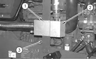
3. Disconnect air conditioner hose (1) and (2) .
4. Remove two nuts (3), the two washers and the two bolts. Remove the clip and air conditioner dryer (5) from bracket (4) .
Installation Procedure
Note: Check the O-ring seals for wear or damage. Use new replacement parts, if necessary.
Illustration 1
g00567098
Illustration 2
g00567098
1. Position the clip and air conditioner dryer (5) to bracket (4) .
2. Install the two bolts, the two washers and two nuts (3) .
3. Install the O-ring seals and connect air conditioner hose (1) and (2) .
4. Evacuate the air conditioner system. Charge the air conditioner system. The correct charge is 2.3 kg (5.07 lb). Refer to Service Manual, SENR5664, "Air Conditioning and Heating Systems with R134a Refrigerant" for the correct procedure. Refer to Special Publication, NEDG5065, "Air Conditioning Tools" for the correct tools.
5. Close the hood. Refer to Operation and Maintenance Manual, SEBU7204, "Engine Compartment Hood - Lower".
1993 - 2024 Caterpillar Inc.
Network For SIS Licensees. Thu Apr 18 01:44:07 UTC+0530 2024
Product: CHALLENGER
Model: 55 CHALLENGER 6NN
Configuration: Challenger 55 Agricultural Tractor 60 in (1524 mm) Base Gauge 6NN00001-UP (MACHINE) POWERED BY 3126 Engine
Disassembly and Assembly
3116 Engine for Challenger 35, and Challenger 45 Agricultural Tractors and 3126 Engine for Challenger 55 Agricultural Tractor Engine Supplement
Media Number -RENR1788-00 Publication Date -01/04/1999 Date Updated -09/10/2001
Air Inlet Heater - Remove and Install
SMCS - 1090-010
Removal Procedure
Hot engine components can cause injury from burns. Before performing maintenance on the engine, allow the engine and the components to cool.
Illustration 1
g00557353
1. Remove four bolts (1) and the four washers. Remove shield (2) from bracket (3) .
i01068753
Illustration 2
g00557354
Illustration 3
g00557355
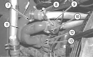
2. Loosen two clamps (4) at the top of air inlet tube (5) .
3. Loosen two clamps (6) at the bottom of the air inlet tube. Remove the air inlet tube.
Illustration 4
g00557356
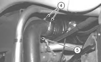
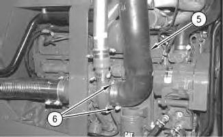
4. Loosen two clamps (7) on hose (8) that is connected to air inlet elbow (11) .
5. Loosen two clamps (10) on hose (9) that is connected to air inlet elbow (11) .
6. Remove nut (12) and ground wire (13) from the air inlet heater.
Illustration 5
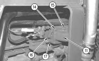
7. Lift boot (16) and disconnect the wire assembly from air inlet heater (17) .
8. Remove bolts (14) and the washers. Remove two bolts (15) and the washers.
Note: Two middle bolts (15) at the top of air inlet elbow (11) cannot be removed until the separation of air inlet elbow (11) and air inlet heater (17) .
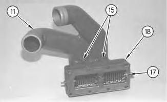
9. Remove air inlet elbow (11), air inlet heater (17) and the gasket from the inlet manifold cover and the hoses.
Illustration 6
10. Separate air inlet elbow (11) and air inlet heater (17). Remove two bolts (15) and the two washers. Remove gasket (18) from the air inlet heater.
Installation Procedure
Note: Check all gaskets, hose clamps and hoses for wear or damage. Use new replacement parts, if necessary.
g00557357
g00557358
Illustration 7
1. Install gasket (18) on air inlet heater (17) .
g00557358
2. Position two bolts (15) and the two washers in air inlet elbow (11). Install the air inlet heater on the air inlet elbow.
Illustration 8
g00557357
3. Install the hoses and clamps that fit on air inlet elbow (11).
Note: The hoses that fit on the air inlet elbow will be easier to install at this time.
4. Install air inlet elbow (11), air inlet heater (17) and the gasket on the inlet manifold cover.
5. Install bolts (14) and the washers. Install two bolts (15) and the washers.
6. Connect the wire assembly to air inlet heater (17). Position boot (16) in place on the wire assembly.
9
7. Position ground wire (13) on the air inlet heater. Install nut (12) .
8. Tighten two clamps (10) on hose (9) that is connected to air inlet elbow (11) .
9. Tighten two clamps (7) on hose (8) that is connected to air inlet elbow (11) .
10
11
10. Install air inlet tube (5). Tighten two clamps (6) at the bottom of the air inlet tube.
11. Tighten two clamps (4) at the top of the air inlet tube.
Illustration
g00557356
Illustration
g00557355
Illustration
g00557354
12
12. Install shield (2) on bracket (3) with four bolts (1) and the four washers.
Copyright 1993 - 2024 Caterpillar Inc. All Rights Reserved. Private Network For SIS Licensees.
Thu Apr 18 01:37:18 UTC+0530 2024
Product: CHALLENGER
Model: 55 CHALLENGER 6NN
Configuration: Challenger 55 Agricultural Tractor 60 in (1524 mm) Base Gauge
Disassembly and Assembly
3116 Engine for Challenger 35, and Challenger 45 Agricultural Tractors and 3126 Engine for Challenger 55 Agricultural Tractor Engine Supplement
Alternator - Remove and Install
SMCS - 1405-010
Removal Procedure
Hot engine components can cause injury from burns. Before performing maintenance on the engine, allow the engine and the components to cool.
Disconnect batteries before performance of any service work.
Note: Put identification marks on all lines, on all hoses, on all wires, and on all tubes for installation purposes. Plug all lines, hoses, and tubes. This helps to prevent fluid loss and this helps to keep contaminants from entering the system.
1. Disconnect the battery.
2. Open the hood and apply the hood latch. Refer to Operation and Maintenance Manual, SEBU7204, "Engine Compartment Hood - Raise/Lower".
Illustration 1
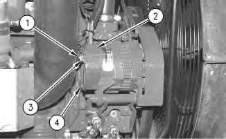
3. Remove bolt (3) and cable assembly (1). Remove nut (4) and guard (2) .
2
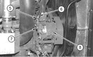
4. Remove cable strap (5). Slide boot (7) up the cable assembly. Disconnect cable assemblies (6) from alternator (8) .
3
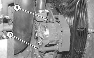
5. Loosen bolts (9) and (10) .
6. Push the alternator toward the engine in order to relieve the belt tension.
g00562529
Illustration
g00562574
Illustration
g00562581
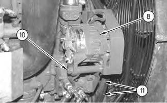
7. Remove bolt (9) and the washer.
4
8. Remove two V-belts (11) from alternator (8) .
9. Remove the nut, the washers and bolt (10) .
10. Remove the alternator.
Installation Procedure
Note: Check the V-belts for wear or damage. Use new replacement parts, if necessary.
Illustration 5
1. Install alternator (8) with bolt (10), the washers and the nut.
Note: Do not tighten bolt (10) at this time.
2. Install two V-belts (11) to the alternator.
Illustration
g00562583
g00562583
6
3. Install bolt (9) and the washer.
4. Position the alternator away from the engine and tighten the V-belts. Refer to Operation and Maintenance Manual, SEBU7204, "Alternator and Fan Belts - Inspect/Adjust/Replace".
5. Tighten the nut on bolt (10) .
6. Connect cable assemblies (6) to alternator (8). Slide boot (7) over the cable assembly. Install cable strap (5) .
Illustration
g00562581
Illustration 7
g00562574
Illustration 8
g00562529
7. Install guard (2) with nut (4) .
8. Install cable assembly (1) with bolt (3) .
9. Release the hood latch and close the hood. Refer to Operation and Maintenance Manual, SEBU7204, "Engine Compartment Hood - Raise/Lower".
10. Connect the battery.
Product: CHALLENGER
Model: 55 CHALLENGER 6NN
Configuration: Challenger 55 Agricultural Tractor 60 in (1524 mm) Base Gauge
Disassembly and Assembly
3116 Engine for Challenger 35, and Challenger 45 Agricultural Tractors and 3126 Engine for Challenger 55 Agricultural Tractor Engine Supplement
Drive Shaft - Remove and Install
SMCS - 3253-010
Removal Procedure
Hot engine components can cause injury from burns. Before performing maintenance on the engine, allow the engine and the components to cool.
Accidental machine starting can cause injury or death to personnel working on the machine.
To avoid accidental machine starting, turn the battery disconnect switch to the OFF position and remove the key.
Place a do not operate tag at the battery disconnect switch location to inform personnel that the machine is being worked on.
Note: The fuel tank assembly was removed for photographic purposes.
i01083698
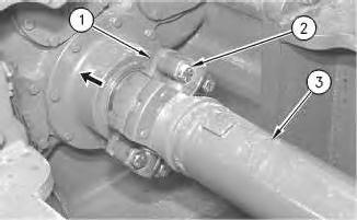
1
1. Remove four bolts (2) that hold drive shaft (3) to yoke (1) .
2. Push yoke (1) toward the transmission.
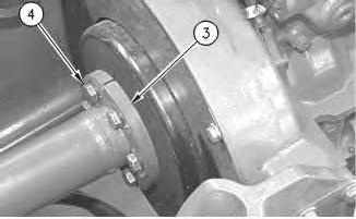
Illustration 2
3. Remove bolts (4) and the washers from drive shaft (3) that connects the drive shaft to the engine.
Installation Procedure
3
Illustration
g00567294
g00567331
Illustration
g00567331
1. Install drive shaft (3) to the engine with bolts (4) and the washers.
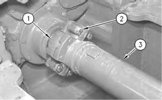
Illustration 4 g00567444
2. Position drive shaft (3) to yoke (1) at the transmission.
3. Install bolts (2) . Copyright 1993 - 2024 Caterpillar Inc. All Rights Reserved. Private Network For SIS Licensees. Thu Apr 18 01:44:53 UTC+0530 2024
Product: CHALLENGER
Model: 55 CHALLENGER 6NN
Configuration: Challenger 55 Agricultural Tractor 60 in (1524 mm) Base Gauge 6NN00001-UP (MACHINE) POWERED BY 3126 Engine
Disassembly and Assembly
3116 Engine for Challenger 35, and Challenger 45 Agricultural Tractors and 3126 Engine for Challenger 55 Agricultural Tractor Engine Supplement Media Number -RENR1788-00
-09/10/2001
Electric Starting Motor - Install
SMCS - 1453-012
Installation Procedure
NOTICE
Do not fill fuel filters with fuel before installing them. Contaminated fuel will cause accelerated wear to fuel system parts.
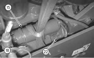
Illustration 1
i01087597
g00568800
1. Use a strap and a suitable lifting device to support solenoid (15) and electric starting motor (18) .
2. Install the solenoid and the electric starting motor. The weight of the electric starting motor is 23 kg (51 lb).
3. Install three bolts (22) and the three washers that hold the electric starting motor to the engine.
This is the sample of the manual click on the download link for complete manual