

545D WHEEL SKIDDER

Note: Use Bookmarks panel to navigate

Product: WHEEL SKIDDER
Model: 545D WHEEL SKIDDER KGP
Configuration: 545D WHEEL SKIDDER KGP00001-UP (MACHINE) POWERED BY C7.1 Engine
Disassembly and Assembly
525D, 535D, 545D and 555D Wheel Skidders C7.1 Engine Supplement
Water Pump - Remove and Install
SMCS - 1361-010; 1361-011; 1361-012; 5614-010
Removal Procedure
Personal injury can result from hot coolant, steam and alkali.
At operating temperature, engine coolant is hot and under pressure. The radiator and all lines to heaters or the engine contain hot coolant or steam. Any contact can cause severe burns.
Remove cooling system pressure cap slowly to relieve pressure only when engine is stopped and cooling system pressure cap is cool enough to touch with your bare hand.
Do not attempt to tighten hose connections when the coolant is hot, the hose can come off causing burns.
Cooling System Coolant Additive contains alkali. Avoid contact with skin and eyes.
1. Drain the coolant. Refer to Refer to Operation and Maintenance Manual, "Cooling System Coolant (ELC) - Change" for the correct draining and filling procedures.
This is the sample of the manual click on the download link for complete manual
DOWNLOAD LINK
For some reason if link does not work download this pdf and then click
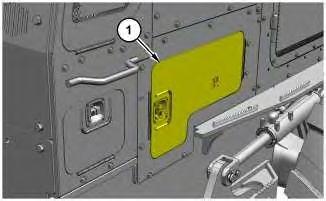
1
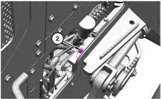
2
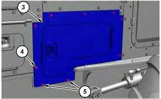
3
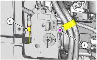
Illustration 4
g06179759
5. Cut the cable strap and disconnect harness assembly (6).
6. Remove bolt (7) and reposition the clip out of the way.
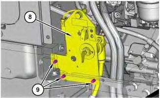
Illustration 5
g06179764
Lower frame has been made transparent for clarity.
7. Remove bolts (9) and reposition bracket assembly (8) out of the way.
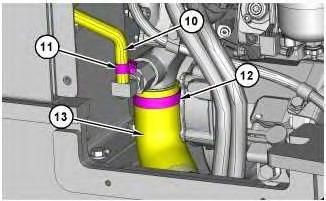
Illustration 6
g06179778
8. Loosen clamp (11) and disconnect hose (10).
9. Loosen clamp (12) and disconnect hose (13).
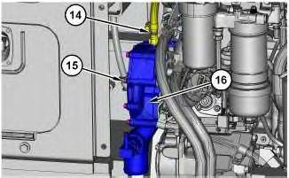
Illustration 7
Hose made transparent for clarity.
10. Disconnect hose assembly (14).
g06179864
11. Remove bolts (15), water pump (16), and the gasket.
Installation Procedure
1. Install water pump (16) in the reverse order of removal.
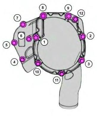
Illustration 8
g06225483
2. Tighten bolts (15) in the sequence shown to a torque of 22 N·m (195 lb in).
Copyright 1993 - 2024 Caterpillar Inc. All Rights Reserved. Private Network For SIS Licensees.
Tue May 14 01:17:58 UTC+0530 2024
Product: WHEEL SKIDDER
Model: 545D WHEEL SKIDDER KGP
Configuration: 545D WHEEL SKIDDER KGP00001-UP (MACHINE) POWERED BY C7.1 Engine
Disassembly and Assembly
525D, 535D, 545D and 555D Wheel Skidders C7.1 Engine Supplement
Water Temperature Regulator - Remove and Install
SMCS - 1355-010
Removal Procedure
Personal injury can result from hot coolant, steam and alkali.
At operating temperature, engine coolant is hot and under pressure. The radiator and all lines to heaters or the engine contain hot coolant or steam. Any contact can cause severe burns.
Remove cooling system pressure cap slowly to relieve pressure only when engine is stopped and cooling system pressure cap is cool enough to touch with your bare hand.
Do not attempt to tighten hose connections when the coolant is hot, the hose can come off causing burns.
Cooling System Coolant Additive contains alkali. Avoid contact with skin and eyes.
1. Drain the coolant. Refer to Refer to Operation and Maintenance Manual, "Cooling System Coolant (ELC) - Change" for the correct draining and filling procedures.
1
2
3
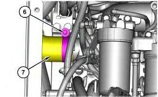
Illustration 4
g06179336
5. Loosen clamp (6) and disconnect hose (7).
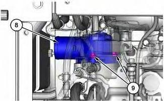
Illustration 5
g06179345
Secondary fuel filter lines and base have been made transparent for clarity.
6. Remove bolts (9) and water temperature regulator housing (8).
7. Remove the water temperature regulator.
Installation Procedure
1. Install the water temperature regulator in the reverse order of removal.
Copyright 1993 - 2024 Caterpillar Inc. All Rights Reserved. Private Network For SIS Licensees. Tue May 14 01:17:29 UTC+0530 2024

Product: WHEEL SKIDDER
Model: 545D WHEEL SKIDDER KGP
Configuration: 545D WHEEL SKIDDER KGP00001-UP (MACHINE) POWERED BY C7.1 Engine
Disassembly and Assembly 525D, 535D, 545D and 555D Wheel Skidders C7.1 Engine Supplement
Bottom Guard (Engine) - Remove and Install
SMCS - 7153-010-ENG; 7153-010
Removal Procedure
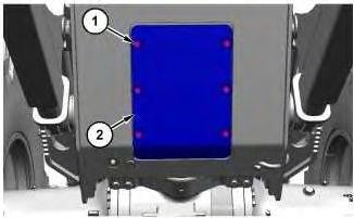
Illustration 1
i07090227
g06221616
1. Remove bolts (1). Use two people and remove bottom guard (2). The weight of bottom guard (2) is approximately 27 kg (60 lb).
Installation Procedure
1. Install bottom guard (2) in the reverse order of removal.
Copyright 1993 - 2024 Caterpillar Inc. All Rights Reserved. Tue May 14 01:17:17 UTC+0530 2024
Product: WHEEL SKIDDER
Model: 545D WHEEL SKIDDER KGP
Configuration: 545D WHEEL SKIDDER KGP00001-UP (MACHINE) POWERED BY C7.1 Engine
Disassembly and Assembly
525D, 535D, 545D and 555D Wheel Skidders C7.1 Engine Supplement
Media Number -KENR7513-03
Publication Date -01/06/2014
Soot Sensor - Remove and Install
SMCS - 108F-010-NS; 1439-010-SOT
Removal Procedure
Start By:
a. Remove the air cleaner.
1. Turn the battery disconnect switch to the OFF position.
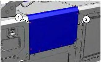
Illustration 1 g06221472
2. Remove bolts (1) and panel assembly (2).
Date Updated -13/09/2017
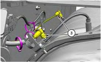
Illustration 2
g06222725
3. Cut the cable straps and disconnect soot sensor (3).
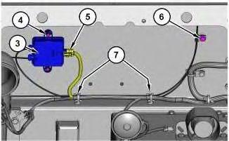
Illustration 3
4. Remove bolts (6) and (7).
5. Disconnect harness assembly (5).
6. Remove bolts (4) and soot sensor (3).
Installation Procedure
g06226954
1. Install soot sensor (3) in the reverse order of removal.
a. Tighten bolts (4) to a torque of 6 ± 1 N·m (53 ± 9 lb in).
b. Tighten soot sensor (3) to a torque of 1.2 ± 0.2 N·m (17 ± 2 lb in). Copyright 1993 - 2024 Caterpillar Inc.
Tue May 14 01:17:06 UTC+0530 2024
For SIS
Product: WHEEL SKIDDER
Model: 545D WHEEL SKIDDER KGP
Configuration: 545D WHEEL SKIDDER KGP00001-UP (MACHINE) POWERED BY C7.1 Engine
Disassembly and Assembly
525D, 535D, 545D and 555D Wheel Skidders C7.1 Engine Supplement
i07764339
Crankshaft Front Seal - Remove and Install
SMCS - 1160-010
Removal Procedure
Table 1 Required Tools
Start By:
a. Remove the vibration damper and pulley.
Illustration 1 g06426654
1. Position Tooling (A) on the nose of the crankshaft. Screw Tooling (A) into crankshaft front seal (2).
Note: Do not damage the edge of the housing for the crankshaft front seal.
2. Screw bolt (1) into Tooling (A) to remove crankshaft front seal (2) from the front cover.
Installation Procedure NOTICE
Keep all parts clean from contaminants.
Contaminants may cause rapid wear and shortened component life.
1. Ensure that the front cover is clean and free from damage.
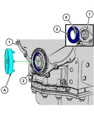
Illustration 2
2. Correctly position a new crankshaft front seal (2) in Position (X) onto front cover (1).
3. Position Tooling (A) onto crankshaft front seal (2).
4. Use Tooling (A) to turn crankshaft front seal (2) in clockwise direction.
5. If it is necessary, to apply a torque greater than 50 N·m (37 lb ft) to install crankshaft front seal (2). Remove crankshaft front seal (2). Inspect the crankshaft front seal and the front cover for faults or damage.
6. If necessary repeat Step 2 through Step 5 to install crankshaft front seal (2).
End By:
a. Install the vibration damper and pulley.
Product: WHEEL SKIDDER
Model: 545D WHEEL SKIDDER KGP
Configuration: 545D WHEEL SKIDDER KGP00001-UP (MACHINE) POWERED BY C7.1 Engine
Disassembly and Assembly
525D, 535D, 545D and 555D Wheel Skidders C7.1 Engine Supplement
Media Number -KENR7513-03
Publication Date -01/06/2014
Flexible Exhaust Pipe - Remove and Install
SMCS - 1061-010
Removal Procedure
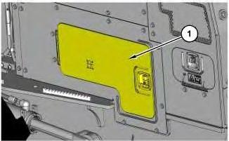
1
Date Updated -13/09/2017
i06943866
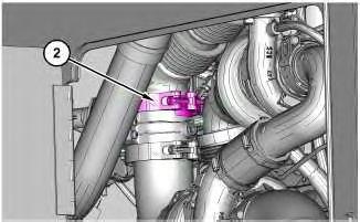
Illustration 2
2. Loosen clamp (2).
g06177859
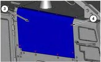
Illustration 3
3. Remove bolts (4) and panel assembly (3).
g06178262
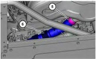
Illustration 4
g06178281
4. Loosen clamp assembly (5) and remove flexible exhaust pipe (6).
Installation Procedure
1. Install flexible exhaust pipe (6) in the reverse order of removal.
a. Use hand tools to tighten clamp assembly (5) to a torque of 35 ± 2 N·m (26 ± 1 lb ft).
b. Use hand tools to tighten clamp (2) to a torque of 12 ± 1 N·m (106 ± 9 lb in).
Copyright 1993 - 2024 Caterpillar Inc. All Rights Reserved. Private Network For SIS Licensees. Tue May 14 01:16:50 UTC+0530 2024
Product: WHEEL SKIDDER
Model: 545D WHEEL SKIDDER KGP
Configuration: 545D WHEEL SKIDDER KGP00001-UP (MACHINE) POWERED BY C7.1 Engine
Disassembly and Assembly
525D, 535D, 545D and 555D Wheel Skidders C7.1 Engine Supplement Media
Solenoid Valve (DEF Heater Coolant) - Remove and Install
SMCS - 5479-CLT
Removal Procedure Table 1
Personal injury can result from hot coolant, steam and alkali.
At operating temperature, engine coolant is hot and under pressure. The radiator and all lines to heaters or the engine contain hot coolant or steam. Any contact can cause severe burns.
Remove cooling system pressure cap slowly to relieve pressure only when engine is stopped and cooling system pressure cap is cool enough to touch with your bare hand.
Do not attempt to tighten hose connections when the coolant is hot, the hose can come off causing burns.
Cooling System Coolant Additive contains alkali. Avoid contact with skin and eyes.
1
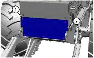
1. Remove bolts (1) and use two people to remove plate (2). The weight of plate (2) is approximately 24 kg (53 lb).
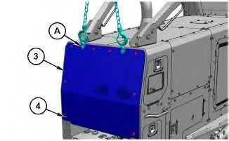
Illustration 2
2. Attach Tooling (A) and a suitable lifting device to plate (3). The weight of plate (3) is approximately 54 kg (120 lb).
3. Remove bolts (4) and plate (3).
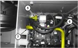
Illustration 3
4. Disconnect harness assembly (5).
5. Loosen the clamps and disconnect hoses (6) and (7).
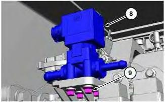
Illustration 4 g06222724
6. Remove four bolts (9) and solenoid valve (DEF heater coolant) (8).
Installation Procedure
1. Install solenoid valve (DEF heater coolant) (8) in the reverse order of removal.
Note: Do not use power tools when tightening four bolts (9).
Copyright 1993 - 2024 Caterpillar Inc. All Rights Reserved. Private Network For SIS Licensees. Tue May 14 01:16:34 UTC+0530 2024
Product: WHEEL SKIDDER
Model: 545D WHEEL SKIDDER KGP
Configuration: 545D WHEEL SKIDDER KGP00001-UP (MACHINE) POWERED BY C7.1 Engine
Disassembly and Assembly 525D, 535D, 545D and 555D Wheel Skidders C7.1 Engine Supplement
i07104992
Vibration Damper and Pulley - Remove and Install
SMCS - 1205-010
Removal Procedure
Table 1 Required Tools
Start By:
a. Remove the batteries.
b. Remove the diesel exhaust fluid tank.
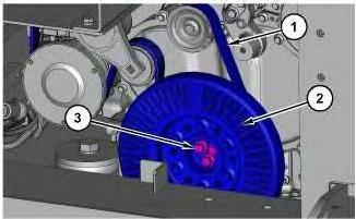
Illustration 1
g06181391
1. Remove belt (1). Refer to Operation and Maintenance Manual, "Belt - Inspect/Adjust/Replace".
2. Remove bolts (3), install Tooling (A), and remove vibration damper (2).
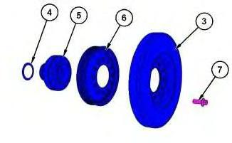
Illustration 2
g06226000
3. Remove bolts (7), pulley (6), and adaptor (5). If necessary, remove the front crankshaft seal to remove friction shim (4).
Installation Procedure
1. Install vibration damper (2) in the reverse order of removal.
a. Tighten bolts (7) to a torque of 115 N·m (85 lb ft).
b. Tighten bolts (3) to a torque of 40 N·m (30 lb ft). Use Tooling (B) to turn bolts (3) and additional 120 degrees.
Tue May 14 01:16:24 UTC+0530 2024
Product: WHEEL SKIDDER
Model: 545D WHEEL SKIDDER KGP
Configuration: 545D WHEEL SKIDDER KGP00001-UP (MACHINE) POWERED BY C7.1 Engine
Disassembly and Assembly
525D, 535D, 545D and 555D Wheel Skidders C7.1 Engine Supplement
Media Number -KENR7513-03
Publication Date -01/06/2014
Manifold (DEF Heater) - Remove and Install
SMCS - 3206-010-CLT; 3206-CLT
Removal Procedure
Start By:
a. Remove the diesel exhaust fluid tank.
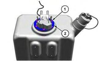
Illustration 1 g06222752
Typical Example
1. Remove bolts (1) and plate (2).
Date Updated -13/09/2017
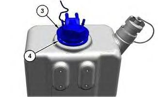
Illustration 2
Typical Example
g06222714
2. Remove manifold assembly (3) and gasket (4)
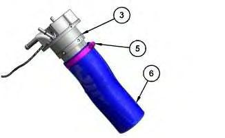
Illustration 3
g06222716
3. Loosen clamp (5) and remove filter assembly (6) from manifold assembly (3).
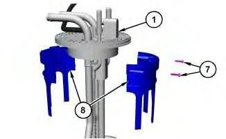
Illustration 4
g06222718
4. Remove screws (7) and base assembly (8) from manifold assembly (1).
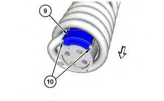
Illustration 5
g06222719
Arrow indicates the direction to remove filter assembly (9).
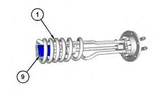
Illustration 6
g06222720
Note: To remove filter assembly (9) from manifold assembly (1), pull outward on tabs (10).
5. Remove filter assembly (9) from manifold assembly (1).
Installation Procedure
1. Install the manifold (diesel exhaust fluid) in the reverse order of removal.
a. Tighten screws (7) to a torque of 1.5 ± 0.1 N·m (13 ± 0.8 lb in).
b. Tighten clamp (5) to a torque of 4.5 ± 0.7 N·m (40 ± 6 lb in).
c. Tighten bolts (1) in an alternating sequence to a torque of 5 ± 1 N·m (44 ± 9 lb in).
Copyright 1993 - 2024 Caterpillar Inc. All Rights Reserved. Private Network For SIS Licensees. Tue May 14 01:16:14 UTC+0530 2024
This is the sample of the manual click on the download link for complete manual
DOWNLOAD LINK
For some reason if link does not work download this pdf and then click