

For some reason if link does not work download this pdf and then click

Product: KNUCKLEBOOM LOADER
Model: 539 KNUCKLEBOOM LOADER 1PZ
Configuration: 539 Knuckle Boom Loader 1PZ00001-UP (MACHINE) POWERED BY 3126 Engine
Disassembly and Assembly
539 Knuckleboom Loader Machine Systems
Media Number -RENR3076-03 Publication Date -01/01/2004 Date Updated -05/01/2004
SMCS - 6331-077; 7000-077
Connection Procedure
Personal injury or death can result from unexpected machine movement.
Do not rely on the stabilizers for support of the machine while you are performing service work on the machine.
The stabilizers may drift at any time, causing unexpected machine movement.
If the machine is connected to the trailer, do not allow the stabilizers to support any of the weight of the machine while you perform any service work on the machine.
If the machine has been separated from the trailer, use adequate blocks to support the weight of the machine while you perform any service work on the machine.
To avoid personal injury, or injury to nearby personnel, due to unexpected machine movement, make sure the stabilizers are not supporting any of the weight of the machine while you perform any service work on the machine.
1. Lower the boom until the grapple is resting on the ground.
2. Carefully lower all four of the stabilizers. Lower the stabilizers until the cylinders are fully extended.
Reference: Refer to Operation and Maintenance Manual, SEBU7172, "Cab Features" for instruction for the operation of the stabilizer controls.
3. Attach a suitable lifting device and a hoist to the machine.
4. Raise the machine until the machine has enough clearance for the installation of the trailer. The weight of the machine is 16375 kg (36100 lb).
5. Move the trailer into position under the machine.
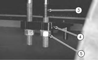
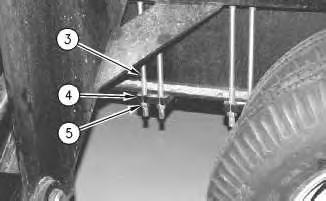
6. Install 64 nuts (5), the washers, 16 plates (4), and 32 studs (3). Tighten nuts (5) to a torque of 800 ± 100 N·m (590 ± 73 lb ft).
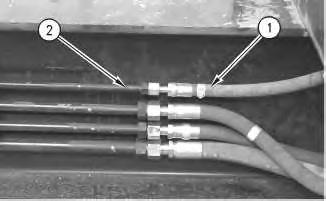
Illustration 3
Typical Example
7. Install all hose assemblies (1) on tube assemblies (2) .
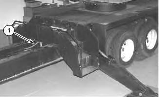
Illustration 4
8. Connect hose assemblies (1) to the machine.
Copyright 1993 - 2024 Caterpillar Inc. All Rights Reserved. Private Network For SIS Licensees. Thu Aug 22 10:22:46 UTC+0530 2024
Product: KNUCKLEBOOM LOADER
Model: 539 KNUCKLEBOOM LOADER 1PZ
Configuration: 539 Knuckle Boom Loader 1PZ00001-UP (MACHINE) POWERED BY 3126 Engine
Disassembly and Assembly
539 Knuckleboom Loader Machine Systems
Media Number -RENR3076-03 Publication Date -01/01/2004 Date Updated -05/01/2004
SMCS - 6331-077; 7000-076
Personal injury or death can result from unexpected machine movement.
Do not rely on the stabilizers for support of the machine while you are performing service work on the machine.
The stabilizers may drift at any time, causing unexpected machine movement.
If the machine is connected to the trailer, do not allow the stabilizers to support any of the weight of the machine while you perform any service work on the machine.
If the machine has been separated from the trailer, use adequate blocks to support the weight of the machine while you perform any service work on the machine.
To avoid personal injury, or injury to nearby personnel, due to unexpected machine movement, make sure the stabilizers are not supporting any of the weight of the machine while you perform any service work on the machine.
Care must be taken to ensure that fluids are contained during performance of inspection, maintenance, testing, adjusting and repair of the product. Be prepared to collect the fluid with suitable containers before opening any compartment or disassembling any component containing fluids.
Refer to Special Publication, NENG2500, "Caterpillar Tools and Shop Products Guide" for tools and supplies suitable to collect and contain fluids on Caterpillar products.
Dispose of all fluids according to local regulations and mandates.
Note: Put identification marks on all lines, on all hoses, on all wires and on all tubes for installation purposes. Plug all lines, all hoses and all tubes. This helps to prevent fluid loss and this helps to keep contaminants from entering the system.
1. Lower the boom until the grapple is resting on the ground.
2. Carefully lower all four of the stabilizers. Lower the stabilizers until the cylinders are fully extended.
Reference: Refer to Operation and Maintenance Manual, SEBU7172, "Cab Features" for instruction for the operation of the stabilizer controls.
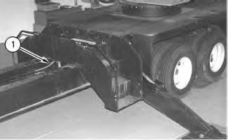
Illustration 1
g00623339
3. Disconnect hose assemblies (1) from the machine.
Illustration 2
Typical Example
4. Remove all hose assemblies (1) from tube assemblies (2) .
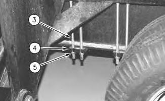
Illustration 3
g00623341
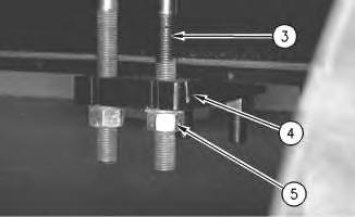
Illustration 4
g00623342
5. Remove 64 nuts (5), the washers, 16 plates (4), and 32 studs (3) .
6. Attach a suitable lifting device and a hoist to the machine.
7. Raise the machine. The weight of the machine is 16375 kg (36100 lb).
8. Remove the trailer from the machine.
Copyright 1993 - 2024 Caterpillar Inc. All Rights Reserved. Private Network For SIS Licensees. Thu Aug 22 10:22:09 UTC+0530 2024
Product: KNUCKLEBOOM LOADER
Model: 539 KNUCKLEBOOM LOADER 1PZ
Configuration: 539 Knuckle Boom Loader 1PZ00001-UP (MACHINE) POWERED BY 3126 Engine
Disassembly and Assembly
539 Knuckleboom Loader Machine Systems
Media Number -RENR3076-03 Publication Date -01/01/2004 Date Updated -05/01/2004
SMCS - 6321-077; 6331-077
Connection Procedure Table 1
Required Tools
Tool Part Number Part Description Qty A 138-7575 Link Bracket 3
NOTICE
Care must be taken to ensure that fluids are contained during performance of inspection, maintenance, testing, adjusting and repair of the product. Be prepared to collect the fluid with suitable containers before opening any compartment or disassembling any component containing fluids.
Refer to Special Publication, NENG2500, "Caterpillar Tools and Shop Products Guide" for tools and supplies suitable to collect and contain fluids on Caterpillar products.
Dispose of all fluids according to local regulations and mandates.
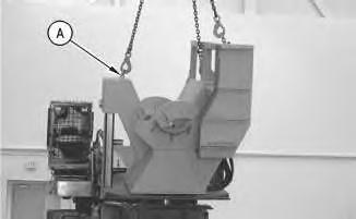
Illustration 1
Typical Example
1. Install Tooling (A). Attach a suitable lifting device and a hoist to the delimber.
2. Put the delimber in position on the trailer. The weight of the delimber is 2225 kg (4900 lb).
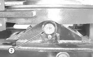
Illustration 2
3. Install two pin assemblies (2) .
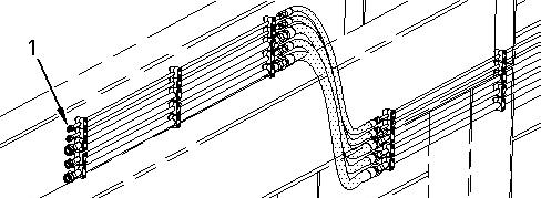
Illustration 3 g00647286
4. Connect five hose assemblies to five tube assemblies (1) .
Copyright 1993 - 2024 Caterpillar Inc. All Rights Reserved. Private Network For SIS Licensees. Thu Aug 22 10:21:42 UTC+0530 2024
Product: KNUCKLEBOOM LOADER
Model: 539 KNUCKLEBOOM LOADER 1PZ
Configuration: 539 Knuckle Boom Loader 1PZ00001-UP (MACHINE) POWERED BY 3126 Engine
Disassembly and Assembly
539 Knuckleboom Loader Machine Systems
Media Number -RENR3076-03 Publication Date -01/01/2004 Date Updated -05/01/2004
SMCS - 6321-076; 6331-076
Separation Procedure Table 1
Required Tools
Tool Part Number Part Description Qty
A 138-7575 Link Bracket 3
Start By:
A. Release the pressure in the hydraulic system. Refer to Disassembly and Assembly, "System Pressure - Release" for the machine that is being serviced.
Care must be taken to ensure that fluids are contained during performance of inspection, maintenance, testing, adjusting and repair of the product. Be prepared to collect the fluid with suitable containers before opening any compartment or disassembling any component containing fluids.
Refer to Special Publication, NENG2500, "Caterpillar Tools and Shop Products Guide" for tools and supplies suitable to collect and contain fluids on Caterpillar products.
Dispose of all fluids according to local regulations and mandates.
Note: Put identification marks on all lines, on all hoses, on all wires and on all tubes for installation purposes. Plug all lines, all hoses and all tubes. This helps to prevent fluid loss and this helps to keep contaminants from entering the system.
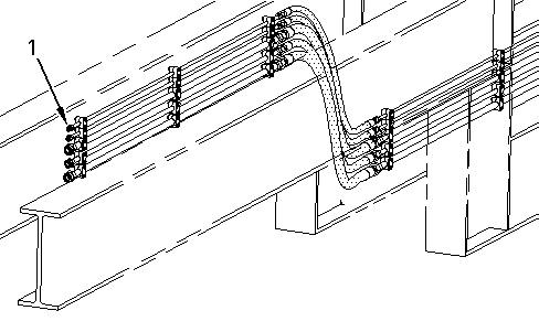
Illustration 1
1. Disconnect five hose assemblies from tube assemblies (1) .
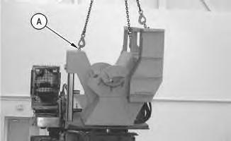
Illustration 2
Typical Example
g00647286
g00648052
2. Install Tooling (A). Attach a suitable lifting device and a hoist to the delimber, as shown.
3. Remove two pin assemblies (2) .
4. Remove the delimber. The weight of the delimber is 2225 kg (4900 lb).
Copyright 1993 - 2024 Caterpillar Inc. All Rights Reserved. Private Network For SIS Licensees. Thu Aug 22 10:21:26 UTC+0530 2024
Product: KNUCKLEBOOM LOADER
Model: 539 KNUCKLEBOOM LOADER 1PZ
Configuration: 539 Knuckle Boom Loader 1PZ00001-UP (MACHINE) POWERED BY 3126 Engine
Disassembly and Assembly
539 Knuckleboom Loader Machine Systems
Media Number -RENR3076-03
Publication Date -01/01/2004 Date Updated -05/01/2004
SMCS - 7305-010
Removal Procedure
i01205894
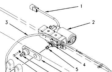
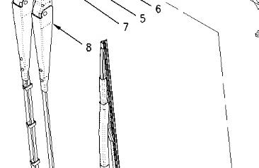
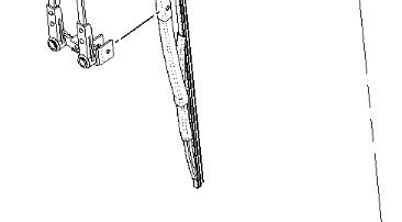
Illustration 1 g00645126
1. Disconnect electrical connector (1) from window wiper motor (2) .
2. Disconnect hose (3) .
3. Remove two nuts (5) and the washers. Remove wiper arm assembly (8) .
4. Support wiper motor assembly (2) inside the cab. Remove bolt (7) and the washer. Remove retaining nut (4). Remove plate (6) .
5. Remove wiper motor assembly (2) .
Installation Procedure
2
NOTICE
Do not operate the wiper motor before the wiper arm assembly is installed.
A new wiper motor is preset in the parked position. If the wiper motor is operated before installation of the wiper arm assembly, misalignment will occur. This can cause damage to the wiper motor, the wiper arm assembly, and/or the window.
Do not manually rotate the wiper arm assembly on the shaft.
1. Support wiper motor assembly (2) inside the cab. Install plate (6). Install bolt (7) and the washer. Install retaining nut (4). Install retaining nut (4) to a torque of 19 ± 1 N·m (14 ± 1 lb ft).
Push the wiper arm assembly straight onto the tapered shaft. If the wiper arm assembly is not installed straight when the shaft turns, the splines will be improperly formed and damage will occur.
2. Position wiper arm assembly (8) on the tapered shaft vertically. Install two nuts (5) and the washers. Tighten two nuts (5) to a torque of 23 ± 1 N·m (16 ± 1 lb ft).
3. Wait for at least thirty minutes. Do not wait for more than four hours. Tighten two nuts (5) again to a torque of 23 ± 1 N·m (16 ± 1 lb ft).
4. Connect hose (3) .
5. Connect electrical connector (1) to window wiper motor (2) . Copyright 1993 - 2024 Caterpillar Inc.
22 10:21:06 UTC+0530 2024
Product: KNUCKLEBOOM LOADER
Model: 539 KNUCKLEBOOM LOADER 1PZ
Configuration: 539 Knuckle Boom Loader 1PZ00001-UP (MACHINE) POWERED BY 3126 Engine
Disassembly and Assembly
539 Knuckleboom Loader Machine Systems
Media Number -RENR3076-03 Publication Date -01/01/2004 Date Updated -05/01/2004
SMCS - 7322-010
Removal Procedure
Personal injury can result from contact with refrigerant.
Contact with refrigerant can cause frost bite. Keep face and hands away to help prevent injury.
Protective goggles must always be worn when refrigerant lines are opened, even if the gauges indicate the system is empty of refrigerant.
Always use precaution when a fitting is removed. Slowly loosen the fitting. If the system is still under pressure, release it slowly in a well ventilated area.
Personal injury or death can result from inhaling refrigerant through a lit cigarette.
Inhaling air conditioner refrigerant gas through a lit cigarette or other smoking method or inhaling fumes released from a flame contacting air conditioner refrigerant gas, can cause bodily harm or death.
Do not smoke when servicing air conditioners or wherever refrigerant gas may be present.
Use a certified recovery and recycling cart to properly remove the refrigerant from the air conditioning system.
1. Recover the air conditioner refrigerant from the air conditioner system.
Reference: Service Manual, SENR5664, "Air Conditioning and Heating Systems with R134a Refrigerant"
Reference: Special Publication, NEDG5065, "Air Conditioning Tools"
1
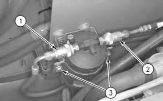
2. Disconnect hose assemblies (1) and (2) .
3. Remove two bolts (3), the washers and the bracket.
4. Remove the receiver-dryer.
Installation Procedure
2
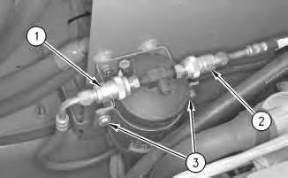
1. Install the receiver-dryer, the bracket, two bolts (3) and washers.
2. Connect hose assemblies (1) and (2) .
3. Evacuate the air conditioner system. Charge the air conditioner system. The correct charge is 1.50 kg (3.25 lb).
Reference: Service Manual, SENR5664, "Air Conditioning and Heating Systems with R134a Refrigerant"
Reference: Special Publication, NEDG5065, "Air Conditioning Tools"
Copyright 1993 - 2024 Caterpillar Inc. All Rights Reserved. Private Network For SIS Licensees. Thu Aug 22 10:20:50 UTC+0530 2024
Product: KNUCKLEBOOM LOADER
Model: 539 KNUCKLEBOOM LOADER 1PZ
Configuration: 539 Knuckle Boom Loader 1PZ00001-UP (MACHINE) POWERED BY 3126 Engine
Disassembly and Assembly
539 Knuckleboom Loader Machine Systems
Media Number -RENR3076-03
Publication Date -01/01/2004
SMCS - 7316-010
Removal Procedure
1
Date Updated -05/01/2004
i01205612
Illustration 2
Rear view of the on/off switch
g00576155
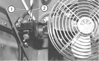
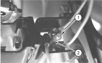
1. Remove screw (1) and disconnect electrical connector (2) from the rear of the on/off switch.
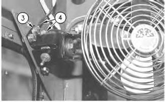
Illustration 3
g00576123
2. Remove bolt (3) and the washer. Disconnect electrical connectors (4) .
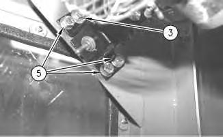
Illustration 4
3. Remove three bolts (5) and the washers.
g00576171
Illustration 5
1. Install three bolts (5) and the washers.
g00576171
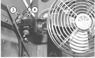
Illustration 6
g00576123
2. Connect electrical connectors (4). Install bolt (3) and the washer.
Illustration 7
g00576165
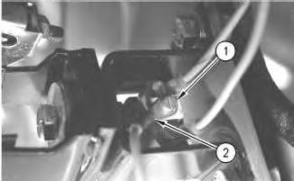
Illustration 8 g00576155
Rear view of the on/off switch
3. Connect electrical connector (2) and install screw (1) on the rear of on/off switch.
Copyright 1993 - 2024 Caterpillar Inc. All Rights Reserved. Private Network For SIS Licensees. Thu Aug 22 10:20:34 UTC+0530 2024
For some reason if link does not work download this pdf and then click