

Note: Use Bookmarks panel to navigate

Product: FRONT SHOVEL
Model: 5080 FRONT SHOVEL 8SL
Configuration: 5080 Excavator 8SL00001-UP (MACHINE) POWERED BY 3406B Engine
Disassembly and Assembly
H45 & H45S HYDRAULIC HAMMER
Media Number -GEBD0001-00
Hammer Tool
SMCS - 6826-010
Date -01/09/1998
Remove & Install Hammer Tool (On the Machine)
Updated -17/10/2001
Tool may fall from hammer during removal. Falling tool may cause personal injury. Make sure that the tool can not fall before attempting to remove it.
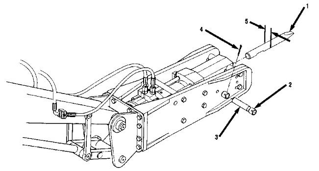
1. Lay the hammer on level ground.
2. Make sure that the carrier's transmission is in neutral and the parking brake is engaged.
3. Stop the engine.
4. Remove cotter pins (4).
5. Remove buffers (2).
6. Remove tool retaining pin (3).
7. Remove tool (1). The weight of the tool is approximately 20 kg (44 lbs).
NOTE: If the hammer is still on the carrier, it may be easier to stick the tool in the ground and lift the hammer off the tool.
NOTE: The following steps are for the installation of the hammer tool.
8. Clean and coat tool and pins with grease.
If you are using old tools, check the tool and the lower tool bushing for wear.
Tool diameter (5) on a new tool is 45 mm (1.77 in). Replace tool if diameter is less than 43 mm (1.69 in).
9. Install tool and align the grooves of the tool with the pin bores.
10. Install retaining pins.
11. Install buffers.
12. Install cotter pins.
1993 - 2024 Caterpillar Inc.
Rights Reserved.
Network For SIS Licensees. Thu Mar 21 12:53:09 UTC+0530 2024
This is the sample of the manual click on the download link for complete manual
DOWNLOAD LINK
For some reason if link does not work download this pdf and then click
Product: FRONT SHOVEL
Model: 5080 FRONT SHOVEL 8SL
Configuration: 5080 Excavator 8SL00001-UP (MACHINE) POWERED BY 3406B Engine
Disassembly and Assembly
H45 & H45S HYDRAULIC HAMMER
Media Number -GEBD0001-00 Publication Date -01/09/1998
Hydraulic Hammer
SMCS - 6333-010; 6333-017
Remove & Install Hydraulic Hammer
Date Updated -17/10/2001
Hammer may roll over when being removed from carrier. The hammer may cause personal injury. Only use a skilled operator to position the carrier for hammer removal.
Hoses are under high pressure. Pressurized oil can cause personal injury. Release oil pressure before opening hose connections. Wait ten minutes for oil pressure to drop and release oil pressure again before opening hose connections.
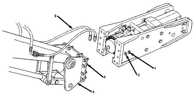
1. Position hammer horizontally on the floor and remove the tool.
2. Disconnect hoses (5). Plug the hoses and the hammer and outlet ports.
3. Remove mounting bracket washers (2) and nuts (1).
4. The carrier, with mounting bracket (4) still attached, can be moved aside.
NOTE: The following steps are for the installation of the hammer.
5. Install mounting bracket (4), mounting bracket bolts (3), washers (2), and nuts (1).
6. Torque bolts (3) to 340 N·m (250 lb ft).
7. Connect hoses (5).
Disassemble & Assemble Hydraulic Hammer
Start By:
Remove hydraulic hammer
The hammer may roll during removal of side plates. The rolling hammer may cause personal injury. Secure hammer from rolling before sideplate bolts are removed.
Do not disassemble hammer before releasing gas pressure from accumulators. Pressure can propel objects and cause serious injury. Release pressure before disassembling accumulators
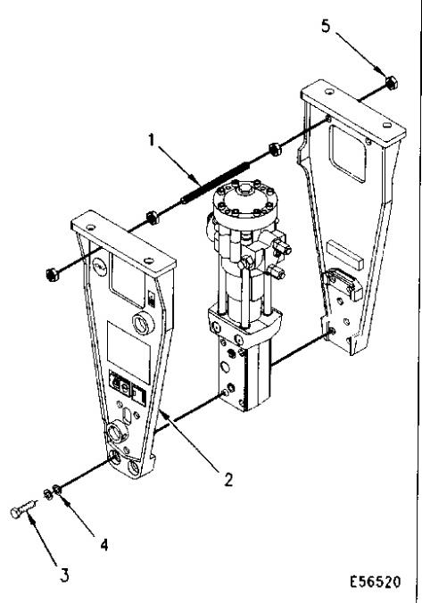
1. Remove hex nuts (5) and threaded rods (1) (if equipped). Remove bolts (3), and lock washers (4).
2. Remove sideplates (2).
3. Remove buffer (7) and locating pins (6) (if equipped).
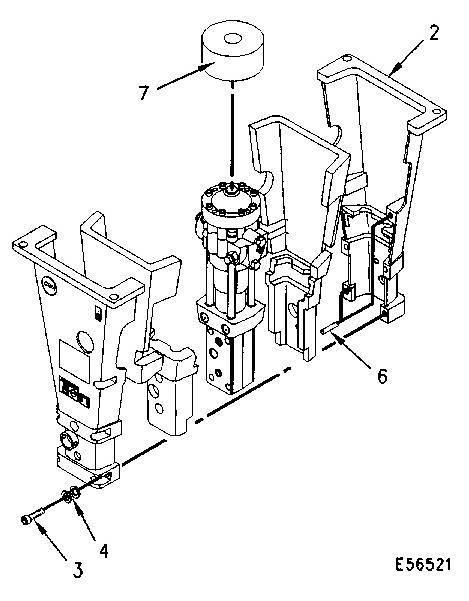
Do not disassemble hammer before releasing gas pressure from accumulators. Pressure can propel objects and cause serious injury. Release pressure before disassembling accumulators
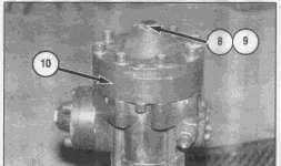
4. Set the hammer onto FT-2639 hydraulic Hammer Stand by removing plug (8) and O-ring (9) from low pressure accumulator (10) and installing a eyebolt in the hammer. The weight of the hammer is 130 kg (290 lbs)
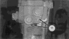
5. Release oil pressure from hammer by carefully opening pressure test ports (11).
6. Remove lifting ring from low pressure accumulator installed in step 4.
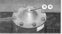
7. CAREFULLY loosen the filling plug (12) and bleed off the nitrogen gas.
8. When nitrogen gas is completely released from low pressure accumulator, remove plug (12) and Usit-ring (13).
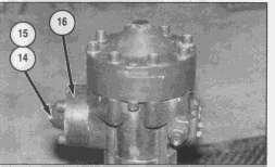
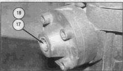
9. Repeat steps 7 & 8 for high pressure accumulator (16) using plug (14), O-ring (15), fill plug (17) and USIT-ring (18).
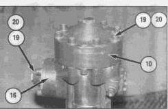
10. Remove bolts (19) and lock washers (20).
11. Remove low pressure accumulator assembly (10).
12. Remove high pressure accumulator assembly (16).
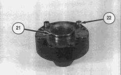
13. Set the low pressure accumulator on the assembly stand or fix it on a vise so that the accumulator is upside down.
14. Remove O-ring (21).
15. Remove bolts (22).
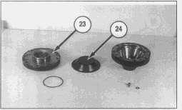
16. Remove accumulator bottom (23) and membrane (24).
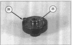
17. Set the high pressure accumulator on the assembly stand or fix it on a vise so that the accumulator is upside down.
18. Remove O-ring (25).
19. Remove bolts (26).
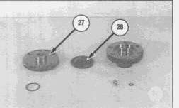
20. Remove accumulator bottom (27) and membrane (28).
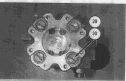
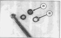
21. Remove rubber rings (29) and locking plates (30).
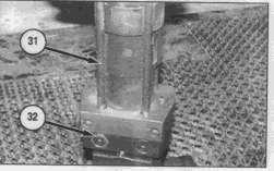
22. Mark each tie rod (31) and its nut (32) as pairs. Mark nut to show top side.
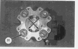
23. Remove tie rods (31) crosswise.
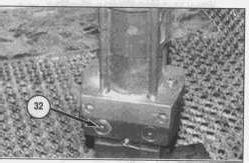
24. Insert 8 mm bolt into nut (32) and pull nut (32) out. Do not turn nuts (32) upside down.
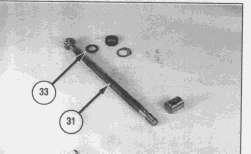
25. Remove washer (33) from tie rod (31).
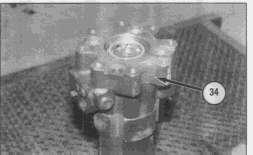
26. Remove valve body (34).
27. Position valve body (34) on a flat surface and turn it upside down to remove distributor and its accompanying parts.
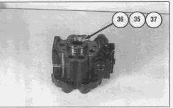
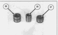
28. Remove steering bushing (36), distributor (35) and assembly ring (37).
29. Remove O-rings from steering bushing (36).
30. Remove seal assembly from inside steering bushing (36).
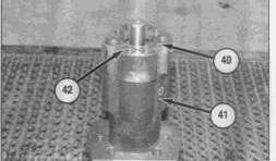
31. Remove O-rings (40 and 42) from cylinder (41).
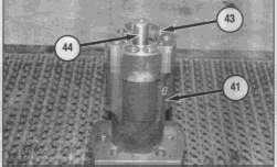
32. Remove guide pin (43).
33. Lift out piston (44).
34. Remove cylinder (41).
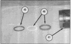
35. Remove wiper (45) and seal assembly (46) from cylinder (41).
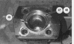
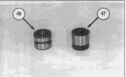
36. Remove thrust ring (47).
37. Remove upper tool bushing (48).
38. Remove guide pin (49).
NOTE: The following steps are for the assembly of the hydraulic hammer.
39. Check all parts for wear or damage.
If necessary, use fine emery cloth or grinding agent. Clean and oil all parts.
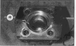
40. Install guide pin (49).
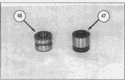
NOTE: Coat the outside of thrust ring (47) and upper tool bushing (48) with anti-seize compound.
41. Install upper tool bushing (48).
42. Install thrust ring (47).
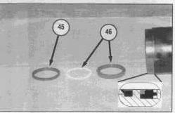
43. Install wiper (45) and seal assembly (46) in cylinder.
44. Apply MoS2 spray on the contact surface between front head and cylinder.
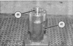
45. Install cylinder (41) into the front head so that the guide pin in the front head aligns with the respective hole in the cylinder(41).
46. Oil piston (44) and install into cylinder (41).
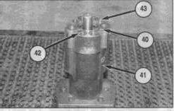
47. Install O-rings (40 and 42).
48. Install guide pin (43).
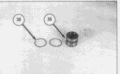
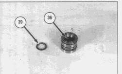
49. Lubricate and install O-rings (38) and seal assembly (39) on steering bushing (36).
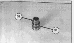
50. Install distributor (36) into steering bushing (37).
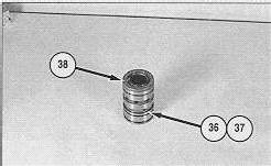
51. Install assembly ring (38) on to steering ring (37) and distributor (36).
52. Distributor (36) must move freely inside bushings.
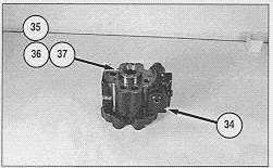
53. Position valve body (34) on a flat surface and install steering bushing (36). distributor (35) and assembly ring (37). Be sure to install assembly with grooved end of distributor (36) exposed.
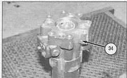
54. Apply MoS2 spray on the contact surface of valve body and cylinder.
55. Install valve body (34) so that the guide pin in the cylinder aligns with the respective hole in the valve body.
56. Use a plastic hammer to seat the valve body(34).
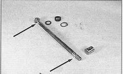
57. Use 4C-4736 Liquid Penetration Kit or 4C-4735 Magnetic Particle test Kit to check for cracks in the tie rod threads or under the head. If cracks are detected, change the tie rod and its nut. Also change the diagonal tie rod and nut.
58. Clean all tie rods and grease threads and the contact surface of tie rods and the valve body.
59. Spread cold-galvanizing spray on the part of tie rod which goes inside the front head.
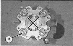
60. Install tie rods (31) and washers. Washers must be installed with chamfer facing up.
Check that each tie rod (31) has the right nut as its pair. Do not turn nuts (32) upside down.
61. Use a torque wrench to tighten the rods crosswise to the torque of 70 N·m (52 lb ft).
62. Tighten an additional 60° with a socket and handle extension.

63. Install locking plates (30) so that the tie rods can not loosen.
64. Install rubber rings (29).
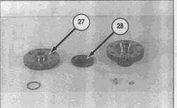
65. Set the high pressure accumulator bottom (27) on the assembly tool, or fix it on a vice.
66. Put a NEW membrane (28) in place. Apply silicone grease on the gas side of the membrane (28) and on the accumulator cover.
67. Install accumulator cover onto accumulator bottom (27).
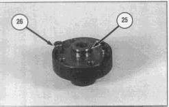
68. Grease threads of hexagonal socket bolts (26).
69. Install lock washers under bolts (26).
70. Torque bolts (26) to 60 N·m (52 lb ft).
71. Install O-ring (25).
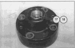
72. Install NEW Usit-ring (18) and existing filling plug (17).
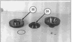
73. Set the low pressure accumulator bottom (23) on the assembly tool, or fix it on a vice.
74. Put a NEW membrane (24) in place. Apply silicone grease on the gas side of the membrane (24) and on the accumulator cover.
75. Install accumulator cover onto accumulator bottom (23).
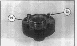
76. Grease threads of hexagonal socket bolts (24).
77. Install lock washers under bolts (24).
78. Torque bolts (24) to 60 N·m (52 lb ft).
79. Lubricate and install O-ring (21).
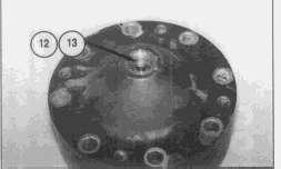
80. Install NEW Usit-ring (13) and existing filling plug (12).
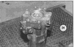
81. Apply MoS2 spray on the contact surface of valve body (34) and accumulators).
82. Lower the accumulators into place using eyebolt.
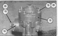
83. Grease threads of hexagonal bolts (19).
84. Install lock washers (20) under bolts (19).
85. Torque bolts (19) to 70 N·m (52 lb ft).
NOTE: The following steps are for the installation of the sideplates.
The outside of the upper mufflers are adhesive. During normal service, there is no need to remove the upper muffler from the side plates. If you need to replace the upper muffler, make sure that the sideplates (2) are clean and dry. Peel the protective film from the upper muffler and attach it into the sideplates. (If equipped)
86. Place one sideplate (2) on a level surface.
87. Install locating pins (6) (if equipped).
88. Grease threads of bolts (3) and threaded rods (1) (if equipped).
89. Place hammer onto side plate(2). Place other sideplate on top of hammer. Compress parts together, if equipped with a muffler.
90. Align sideplate mounting holes to carrier before tightening bolts.
91. Torque bolts to 250 N·m (184 lb ft).
92. Install buffer (7) (if equipped). Copyright 1993 - 2024 Caterpillar Inc.
Product: FRONT SHOVEL
Model: 5080 FRONT SHOVEL 8SL
Configuration: 5080 Excavator 8SL00001-UP (MACHINE) POWERED BY 3406B Engine
Disassembly and Assembly
H45 & H45S HYDRAULIC HAMMER
Media Number -GEBD0001-00
Lower Tool Bushing
SMCS - 6826-010
Date -01/09/1998 Date Updated -17/10/2001
Remove & Install Lower Tool Bushing (On the Machine)
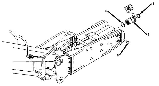
1. Set the hammer on level ground.
2. Make sure that the carrier's transmission is in neutral and the parking brake is engaged.
3. Stop the engine.
4. Remove the tool.
5. Remove split pins (3).
6. Remove lower tool bushing (2).
7. Remove seal (1) and O-ring (4) from lower tool bushing (2).
NOTE: The following steps are for the installation of the lower tool bushing
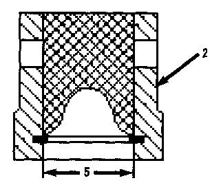
8. Clean all parts and check lower tool bushing for wear.
Inner diameter (5) on new lower tool bushing is 45 mm (1.77 in). Replace bushing if diameter (5) is more than 47 mm (1.85 in).
Apply MoS2 spray to the contact surfaces of lower tool bushing and front head.
9. Install seal (1) and O-ring (4) on lower tool bushing (2).
10. Install lower tool bushing (2).
Align the holes in the lower tool bushing with the holes in the front head.
11. Install split pins (3).
12. Install the tool. Copyright 1993 - 2024 Caterpillar Inc. All Rights Reserved. Private Network For SIS Licensees. Thu Mar 21 12:53:34 UTC+0530 2024
Product: FRONT SHOVEL
Model: 5080 FRONT SHOVEL 8SL
Configuration: 5080 Excavator 8SL00001-UP (MACHINE) POWERED BY 3406B Engine
Disassembly and Assembly
H45 & H45S HYDRAULIC HAMMER
Media Number -GEBD0001-00
Date -01/09/1998 Date Updated -17/10/2001
Pressure Reducing Valve (PRV)
SMCS - 5077-045; 5117-025; 5117-010
Remove & Install Pressure Reducing Valve
Pressure may be retained in hammer. Personal injury may be caused by pieces under pressure.. Release pressure in hammer before removing valve.
The pressure reducing valve can be removed without removing the power cell from the sideplates. The pressure reducing valve is located in the valve body behind pressure and return line ports.
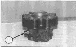
1. Remove spring housing (1).
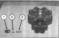
2. Remove spring (3) and shims (2) from inside of spring housing (1).
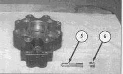
4. Remove plug (6).
5. Remove spool (5) from the valve body by pushing it towards plug (6). Do not push towards spring housing (1).
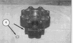
3. Remove seal (6) from inside valve body located on spring housing (1) side.
NOTE: The following steps are for the installation of the pressure reducing valve.
6. Check all parts for wear and damage. If necessary, use fine emery cloth or grinding agent. Clean and oil all parts.
7. Install new seal (4) into valve body.
8. Install spool (5) into the valve body from plug (6) end only. Do not push spool too far, insert just enough to install plug (6).
9. Install shims (2) into spring housing (1) applying some grease.
10. Install spring (3) and spring housing (1) into valve body.
11. Torque plug (5) to 150 N·m (110 lb ft).
12. Torque spring housing (1) to 150 N·m (110 lb ft).
Pressure Reducing Valve Adjustment
When pre-load of the spring changes, the impact energy changes as well.
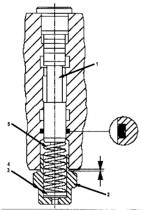
The impact energy is preset at the factory with shim plates (3 and 4).
The hammer operating pressure can be readjusted to specifications by adding or removing shim plates (3 and 4) between spring (5) and spring housing (2).
Adding shim plates increases operating pressure and removing shim plates reduces operating pressure. Always put a thick shim against the spring. Cover shims and spring with grease to stay in place during assembly
The pre-load is measured as follows:
1. Tighten the spring housing until you feel the spring (5) touch spool (2) without compressing it.
2. Measure the gap between valve body and spring housing with a feeler gauge.
3. The gap should be 1.5 mm (0.059 in).
4. Add or remove shims, as necessary, to obtain correct measurement.
5. Measure operating pressure after adjustment. Make reference to the testing and adjusting manual.
NOTE: 1 mm (0.04 in) shim changes low pressure by 3 bar (43 psi) and operating pressure by 8 bar (116 psi).
Charging Accumulators
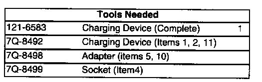
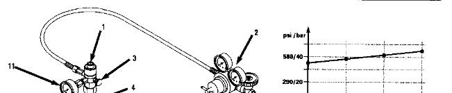
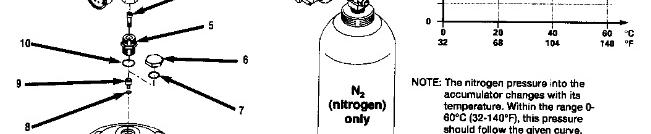

Use only dry nitrogen (N2) for charging accumulators. The use of other gas may cause accumulators to explode.
1. Install a new Usit-ring (8), use existing filling plug (9) on accumulator unless plug (9) is damaged.
2. Connect charging system to the accumulator: install pin (4), adapter (5), O-ring (10), and charging device (1).
3. Close discharge valve (3) on charging device (1).
4. Open filling plug (9) through the charging device (1) three turns.
5. Carefully open nitrogen gas bottle valve (2) and set regulator (if used) to preliminary pressure of 4000 kPa (580 psi) on high pressure accumulator and to 1000 kPa (145 psi) on the low pressure accumulator.
6. Wait 10 minutes for nitrogen gas to stabilize inside accumulator.
7. Readjust accumulator pressure on charging device gauge (11) to the final specification, which is 4000 kPa (580 psi) on high pressure accumulator and 1000 kPa (145 psi) on the low pressure accumulator.
8. Torque filling plug (9) to 20 N·m (15 lb ft) maximum.
9. Release pressure from charging hose by opening discharge valve (3) on charging device.
10. Remove charging device (1), adapter (5), O-ring (10), and pin (4) from accumulator.
11. Check accumulator for nitrogen leak in Usit-ring area by filling pin area (4) with thin oil. If gas bubbles appear, discharge gas and replace Usit-ring.
12. Repeat Steps 1 through 10 if gas bubbles appear.
13. Install protective plug (6) with O-ring (7).
14. Torque plug to 150 N·m (110 lb ft) Copyright 1993 - 2024 Caterpillar Inc. All Rights Reserved.
Network For SIS Licensees. Thu Mar 21 12:53:52 UTC+0530 2024
This is the sample of the manual click on the download link for complete manual
DOWNLOAD LINK
For some reason if link does not work download this pdf and then click