
This is the sample of the manual click on the download link for complete manual
DOWNLOAD LINK
For some reason if link does not work download this pdf and then click

Product: BACKHOE LOADER
Model: 450F BACKHOE LOADER HJR
Configuration: 450F Backhoe Loader HJR00001-UP (MACHINE) POWERED BY C4.4 Engine
Disassembly and Assembly
C4.4 Engines for Caterpillar Built Machines
Media Number -KENR6082-21 Publication Date -01/10/2013 Date Updated -30/01/2019
Accessory Drive - Assemble
SMCS - 1207-016
Assembly Procedure Table 1 Required Tools
NOTICE
Keep all parts clean from contaminants.
Contaminants may cause rapid wear and shortened component life.
i03001183
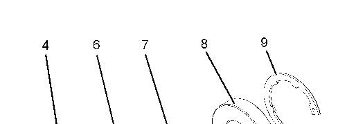
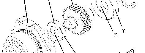

Illustration 1 g01440577
Typical example
1. Inspect the condition of the teeth and the splines of gear (7) for wear or damage. Inspect bearing (6) and bearing (8). Inspect circlip (9), and front housing (4) for wear or damage. Replace any components that are worn or damaged.
2. Apply a small continuous bead of Tooling (B) to inner Surface (X) of bearing (6). Place the gear shaft on a suitable support. Press on the inner race of bearing (6) until bearing (6) is against the shoulder of gear (7). Remove any excess sealant.
3. Apply a small continuous bead of Tooling (B) to inner Surface (Z) of bearing (8). Place the inner race of bearing (8) onto a suitable support. Press the shaft of gear (7) onto bearing (8) until the shoulder of the gear is against the bearing. Remove any excess sealant.
4. Apply a small continuous bead of Tooling (B) to outer Surface (Y) of bearing (6) and bearing (8). Place accessory drive housing (4) on a suitable support. Press the assembly of the gear into the accessory drive housing. Ensure that bearing (6) is against the front face of the recess in accessory drive housing (4). Remove any excess sealant.
5. Install circlip (9) into the groove in accessory drive housing (4). Ensure that circlip (9) is correctly positioned in the groove.
Product: BACKHOE LOADER
Model: 450F BACKHOE LOADER HJR
Configuration: 450F Backhoe Loader HJR00001-UP (MACHINE) POWERED BY C4.4 Engine
Disassembly and Assembly
C4.4 Engines for Caterpillar Built Machines Media
Accessory Drive - Disassemble
SMCS - 1207-015
Disassembly Procedure Table 1
Keep all parts clean from contaminants. Contaminants may cause rapid wear and shortened component life.
NOTICE
Care must be taken to ensure that fluids are contained during performance of inspection, maintenance, testing, adjusting and repair of the product. Be prepared to collect the fluid with suitable containers
before opening any compartment or disassembling any component containing fluids.
Dispose of all fluids according to local regulations and mandates.
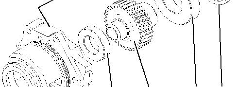

Illustration 1 g01440573
Typical example
1. Remove circlip (9) from accessory drive housing (4).
2. Place accessory drive housing (4) onto a suitable support. Press the assembly of gear (7), bearing (6) and bearing (8) out of accessory drive housing (4).
3. Use a Tooling (A) in order to remove bearing (6) and bearing (8) from gear (7).
Product: BACKHOE LOADER
Model: 450F BACKHOE LOADER HJR
Configuration: 450F Backhoe Loader HJR00001-UP (MACHINE) POWERED BY C4.4 Engine
Disassembly and Assembly
C4.4 Engines for Caterpillar Built Machines
Media Number -KENR6082-21 Publication Date -01/10/2013 Date Updated -30/01/2019
Accessory Drive - Install
SMCS - 1207-012
Installation Procedure Table 1
Required Tools
NOTICE
Keep all parts clean from contaminants.
Contaminants may cause rapid wear and shortened component life.
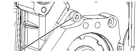
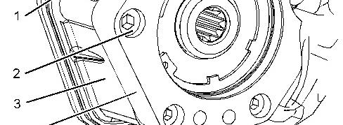
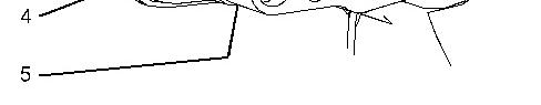
Illustration 1 g01441026
Typical example
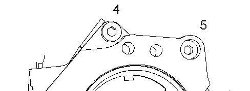
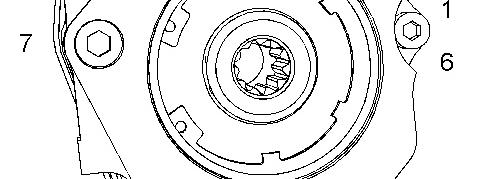

Illustration 2 g01444555
Sequence for tightening accessory drive
1. Inspect the bore in front housing (3) for damage. If necessary, replace the front housing. Refer to Disassembly and Assembly, "Housing (Front) - Remove" and Disassembly and Assembly, "Housing (Front) - Install".
2. Lightly lubricate a new O-ring seal (5) (not shown) with Tooling (C). Install the O-ring seal (not shown) into the groove in accessory drive housing (4).
3. Lightly lubricate all bearings, and all gears with clean engine lubricating oil. Install the assembly of the accessory drive to the front housing. Ensure that the flange on the accessory drive housing is flush with the front housing.
4. Apply Tooling (D) to allen head screws (1) and allen head screw (2).
5. Install allen head screws (1) and allen head screw (2) to accessory drive housing (4).
6. Tighten allen head screws (1) to a torque of 22 N·m (16 lb ft).
Tighten allen head screw (2) to a torque of 44 N·m (32 lb ft). Tighten allen head screws (1) and (2) in the sequence that is shown in Illustration 2.
7. Ensure that there is tactile backlash between the idler gear and the accessory drive gear.
Copyright 1993 - 2024 Caterpillar Inc. All Rights Reserved. Wed Mar 6 10:26:42 UTC+0530 2024
Product: BACKHOE LOADER
Model: 450F BACKHOE LOADER HJR
Configuration: 450F Backhoe Loader HJR00001-UP (MACHINE) POWERED BY C4.4 Engine
Disassembly and Assembly
C4.4 Engines for Caterpillar Built Machines
Media Number -KENR6082-21 Publication Date -01/10/2013 Date Updated -30/01/2019
Accessory Drive - Remove
SMCS - 1207-011
Removal Procedure
NOTICE
Keep all parts clean from contaminants.
Contaminants may cause rapid wear and shortened component life.
NOTICE
Care must be taken to ensure that fluids are contained during performance of inspection, maintenance, testing, adjusting and repair of the product. Be prepared to collect the fluid with suitable containers before opening any compartment or disassembling any component containing fluids.
Dispose of all fluids according to local regulations and mandates.
Illustration 1 g01441026
Typical example
1. Remove allen head screw (1) from accessory drive housing (4). Remove allen head screws (2) from accessory drive housing (4).
2. Remove accessory drive housing (4) from front housing (3).
3. Remove O-ring seal (5) (not shown) from accessory drive housing (4).
Copyright 1993 - 2024 Caterpillar Inc. All Rights Reserved. Private Network For SIS Licensees.
Wed Mar 6 10:25:21 UTC+0530 2024
Product: BACKHOE LOADER
Model: 450F BACKHOE LOADER HJR
Configuration: 450F Backhoe Loader HJR00001-UP (MACHINE) POWERED BY C4.4 Engine
Disassembly and Assembly
C4.4 Engines for Caterpillar Built Machines
Media Number -KENR6082-21
Air Compressor - Remove and Install
SMCS - 1803-010
Removal Procedure
Table 1
Tools
B 230-6283 Timing Pin (Crankshaft) 1
C 1P-2320 Combination Puller 1
(1) The Crankshaft Turning Tool is used on the front pulley. (2) This Tool is used in the aperture for the electric starting motor.
Note: Either Tooling (A) can be used. Use the Tooling that is most suitable.
NOTICE
Care must be taken to ensure that fluids are contained during performance of inspection, maintenance, testing, adjusting and repair of the product. Be prepared to collect the fluid with suitable containers before opening any compartment or disassembling any component containing fluids.
Dispose of all fluids according to local regulations and mandates.
NOTICE
Keep all parts clean from contaminants.
Contaminants may cause rapid wear and shortened component life.
Note: Put identification marks on all hoses, on all hose assemblies and on all tube assemblies for installation purposes. Plug all hose assemblies and tube assemblies. This helps to prevent fluid loss and this helps to keep contaminants from entering the system.
Do not disconnect the air lines until the air pressure in the system is at zero. If hose is disconnected under pressure it can cause personal injury.
1. Release the pressure from the air system.
2. Drain the coolant from the cooling system into a suitable container for storage or for disposal. Refer to Operation and Maintenance Manual, "Cooling System Coolant - Change" for the correct draining procedure.
3. Remove the front cover. Refer to Disassembly and Assembly, "Front Cover - Remove and Install".
4. If the engine is equipped with a hydraulic pump on the rear of the air compressor, remove the hydraulic pump.
5. Use Tooling (A) in order to rotate the crankshaft so that number one piston is at the top center position on the compression stroke. Refer to Systems Operation, Testing and Adjusting, "Finding Top Centre Position for No.1 Piston".
Note: The air compressor must be timed with the engine in order to minimize engine vibration.
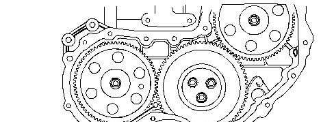

Illustration 1 g01272266
Typical example
6. Install Tooling (B) through Hole (X) in the front housing. Use Tooling (B) in order to lock the crankshaft.
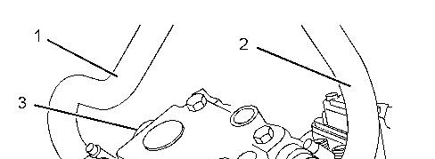
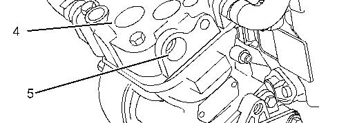
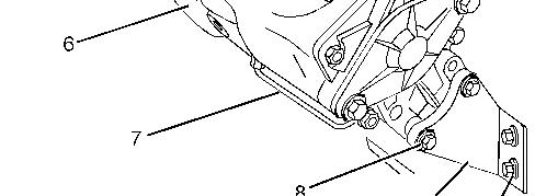

Illustration 2 g01250794
Typical example
7. Disconnect coolant hose (1) and coolant hose (2) from air compressor (4).
8. Disconnect the air line from port (3) and air line from port (5).
9. Remove tube assembly (7) from air compressor (4) and from the cylinder block.
10. Remove bolts (8) and bolts (10) from support bracket (9) and remove the support bracket.

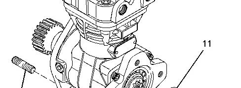
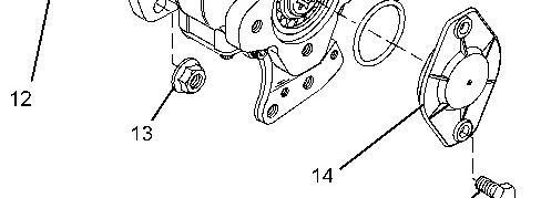

Illustration 3 g01250816
Typical example

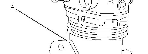
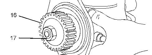

Illustration 4 g01250889
Typical example
11. Support air compressor (4). Remove nuts (13) and remove the air compressor from the front housing.
12. If necessary, remove studs (12) from the front housing.
13. Remove O-ring seal (18) from air compressor (4).
14. If necessary, remove bolts (15) and remove plate (14). Remove O-ring seal (11) from plate (14). Refer to Illustration 3.
15. If necessary, remove nut (17) and remove the spring washer. Use Tooling (C) in order to remove gear (16) from the crankshaft of the air compressor.
Installation Procedure
Table 2
Required Tools
Tool Part Number
B 230-6283 Timing Pin (Crankshaft) 1
D 4C-9506 Retaining Compound 1
E 1U-6396 O-Ring Assembly Compound 1
NOTICE
Keep all parts clean from contaminants.
Contaminants may cause rapid wear and shortened component life.
NOTICE
Care must be taken to ensure that fluids are contained during performance of inspection, maintenance, testing, adjusting and repair of the product. Be prepared to collect the fluid with suitable containers before opening any compartment or disassembling any component containing fluids.
Dispose of all fluids according to local regulations and mandates.
Illustration 5 g01250889
Typical example
1. If necessary, follow Step 1.a through Step 1.b in order to install the gear to the air compressor.
a. Ensure that the shaft of air compressor (4) is clean and dry. Ensure that gear (16) is clean and free from damage.
b. Install gear (16) and a new spring washer to the shaft of the air compressor.
c. Apply Tooling (D) to the threads of the shaft. Install nut (17) to the shaft of air compressor (4). Tighten the nut to a torque of 120 N·m (89 lb ft).
2. Install the O-ring seal (18) to air compressor (4). Use Tooling (E) in order to lubricate the O -ring seal.
3. Ensure that number one piston is at the top center position on the compression stroke. Refer to the Systems Operation, Testing and Adjusting, "Finding Top Center Position for No. 1 Piston".
Note: The air compressor must be timed with the engine in order to minimize engine vibration.


Illustration 6 g01272266
Typical example
4. Ensure that Tooling (B) is installed in Hole (X) in the front housing. Use Tooling (B) in order to lock the crankshaft in the correct position.
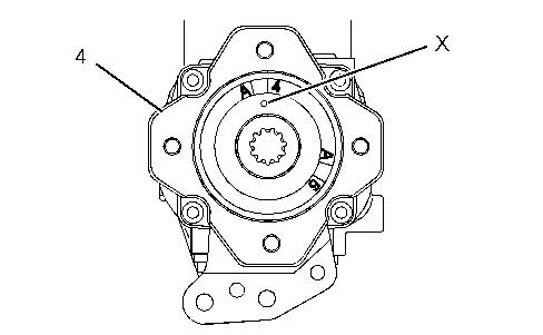
Illustration 7 g01250968
Typical air compressor with a SAE drive
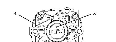

Illustration 8 g01251223
Typical air compressor with a DIN drive
5. Rotate the crankshaft of the air compressor until the timing Mark (X) is aligned with the timing Mark A4 on the rear face of air compressor (4). Refer to Illustration 7 for air compressors with a SAE drive. Refer to Illustration 8 for air compressors with a DIN drive.
Illustration 9 g01250816
Typical example
6. If necessary, install studs (12) to the front housing.
7. Align the air compressor (4) with studs (12). Install the air compressor to the front housing. If necessary, rotate the crankshaft of the air compressor in a clockwise direction in order to align the gears.
Note: Ensure that timing Mark (X) is aligned with the timing mark A4. Refer to Illustration 7 for air compressors with a SAE drive. Refer to Illustration 8 for air compressors with a DIN drive.
8. Install nuts (13). Tighten the nuts to a torque of 78 N·m (58 lb ft).
9. If necessary, follow Step 9.a through Step 9.c in order to install cover (14).
a. Install a new O-ring seal (11) to cover (14). Use Tooling (E) in order to lubricate the O-ring seal.
b. Install cover (14) to air compressor (4).
c. Install bolts (15). Tighten the bolts to a torque of 13 N·m (9.5 lb ft).
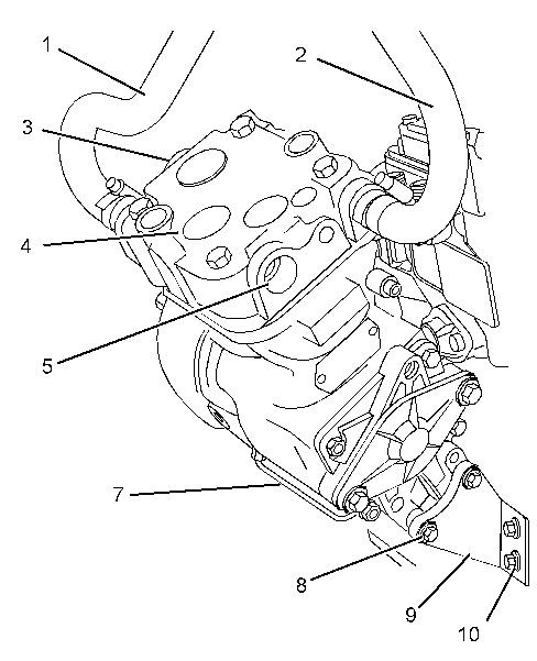
Illustration 10 g01522084
Typical example
10. Position support bracket (9) onto air compressor (4). Install bolts (8) finger tight.
11. Install bolts (10) finger tight.
12. Tighten bolts (8) to a torque of 22 N·m (16 lb ft). Tighten bolts (10) to a torque 22 N·m (16 lb ft).
Note: Ensure that the air compressor is not stressed as the bolts are tightened.
13. Install tube assembly (7) to air compressor (4) and to the cylinder block. Tighten the nuts to a torque of 9 N·m (80 lb in).
14. Remove Tooling (B) from Hole (X) in the front housing.
15. Install the front cover. Refer to Disassembly and Assembly, "Front Cover - Remove and Install".
16. If the engine is equipped with a hydraulic pump on the rear of the air compressor, install the hydraulic pump.
17. Connect the air line to port (3) and air line to port (5) in the air compressor.
18. Connect coolant hose (1) and coolant hose (2) to air compressor (4).
19. Fill the cooling system with coolant to the correct level. Refer to the Operation and Maintenance Manual.
Copyright 1993 - 2024 Caterpillar Inc. All Rights Reserved. Private Network For SIS Licensees.
Wed Mar 6 10:55:41 UTC+0530 2024
This is the sample of the manual click on the download link for complete manual
DOWNLOAD LINK
For some reason if link does not work download this pdf and then click