Note: Use Bookmarks panel to navigate
Product: BACKHOE LOADER
Model: 414E BACKHOE LOADER ELB
Configuration: 414E Backhoe Loader ELB00001-UP (MACHINE) POWERED BY 3054 Engine
Disassembly and Assembly
414E, 416E, 420E, 422E, 428E, 430E, 432E, 434E, 442E and 444E Backhoe Loaders Power Train
System Pressure - Release
SMCS - 4250-553-PX; 4300-553-PX; 5050-553-PX
Release Procedure
1. Park on a level surface. If you must park on a grade, chock the machine.
i02989945
2. Apply the service brake in order to stop the machine. Move the transmission control lever to the NEUTRAL position.
3. Move the speed control lever to the LOW IDLE position.
4. Engage the parking brake.
5. Engage the transmission neutral lock.
6. Lower all attachments to the ground.
7. Stop the engine.
8. Turn the engine start switch key to OFF position for 4 seconds.
9. Turn the engine start switch key back to ON position.
10. Press the hydraulic shutoff switch to the ON position.
11. Operate all hydraulic controls through all positions in order to relieve hydraulic pressure. Repeat this step until all hydraulic pressure is released.
12. Move the hydraulic control levers to the HOLD position.
13. Turn the engine start switch to OFF position and remove the key. Copyright 1993 - 2025 Caterpillar Inc. All Rights Reserved.
Feb 8 01:23:40 UTC+0700 2025
This is the sample of the manual click on the download link for complete manual
For some reason if link does not work download this pdf and then click
Product: BACKHOE LOADER
Model: 414E BACKHOE LOADER ELB
Configuration: 414E Backhoe Loader ELB00001-UP (MACHINE) POWERED BY 3054 Engine
Disassembly and Assembly
414E, 416E, 420E, 422E, 428E, 430E, 432E, 434E, 442E and 444E Backhoe Loaders Power Train Media
Tire and Rim (Front) - Remove and Install
SMCS - 4202-010-FR
Removal Procedure
Table 1 Required Tools
i06892787
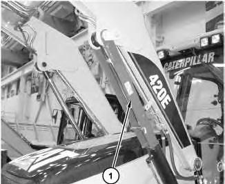
Illustration 1 g01237930
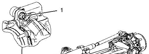
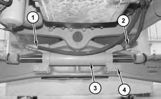
1. Raise the bucket. Install cylinder lock (1).
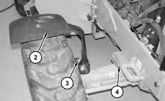
2
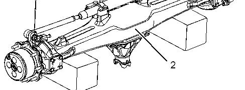
2. Remove nuts (3) and fender (2). Place suitable cribbing (4) between the front axle and the frame on each side of the machine. This will keep the front axle from oscillating.
3
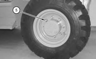
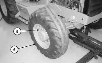
3. Loosen lug nuts (5). Do not remove lug nuts (5) now. Repeat for the other side.
Illustration 4
Illustration
g01116896
Illustration
g01116902
g01116891
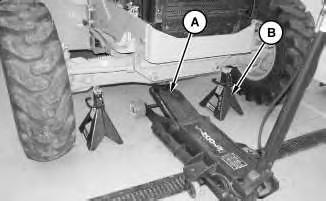
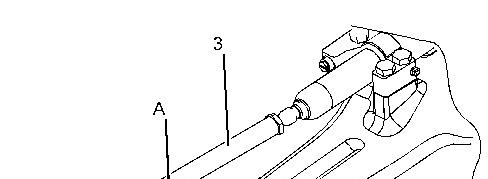
4. Use Tooling (A) to raise the machine. Position Tooling (B) under the frame of the machine. Use Tooling (A) to lower the machine onto Tooling (B).
Illustration 5
5. Attach a suitable lifting device to the tire and rim (6). The combined weight of the tire and rim (6) is approximately 70 kg (155 lb). Remove lug nuts (5) and remove the tire and rim (6).
Installation Procedure
Table 2
Illustration 6
1. Use Tooling (A) to raise the machine.
7
2. Attach a suitable lifting device to the tire and rim (6). The combined weight of the tire and rim (6) is approximately 70 kg (155 lb). Apply a drop of oil on lug nuts (5). Install the rear tire and rim (6) and install lug nuts (6). Do not tighten lug nuts (6) now.
Illustration 8
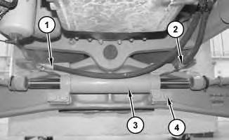
3. Install fender (2) and nuts (3). Remove suitable cribbing (4).
Illustration 9
Illustration
g01237945
g01116896
g01116902
4. Remove Tooling (B) from the frame of the machine. Use Tooling (A) to lower the machine onto the ground. Tighten lug nuts (5) to a torque of 190 ± 40 N·m (140 ± 30 lb ft). Then, turn lug nuts (5) by an extra 60° ± 5°.
10 g01237930
5. Remove cylinder lock (1).
Copyright 1993 - 2025 Caterpillar Inc. All Rights Reserved. Private Network For SIS Licensees. Sat Feb 8 01:24:29 UTC+0700 2025
Illustration
Product: BACKHOE LOADER
Model: 414E BACKHOE LOADER ELB
Configuration: 414E Backhoe Loader ELB00001-UP (MACHINE) POWERED BY 3054 Engine
Disassembly and Assembly
414E, 416E, 420E, 422E, 428E, 430E, 432E, 434E, 442E and 444E Backhoe Loaders Power Train Media Number -RENR6475-13
i02307210
Tie Rod (Steering)(Front) - Remove and Install - Two-Wheel Drive
SMCS - 4318-010-ZH; 4318-010
S/N - BXE1-UP
S/N - CBD1-UP
S/N - DDT1-UP
S/N - DPH1-UP
S/N - EAT1-UP
S/N - ELB1-UP
S/N - FSH1-UP
S/N - GKZ1-UP
S/N - HBE1-UP
S/N - KMW1-UP
S/N - LBE1-UP
S/N - MFG1-UP
S/N - PHC1-UP
S/N - SHA1-UP
S/N - TMS1-UP
Removal Procedure
1P-2321 Combination Puller 1
Illustration 1
g01155584
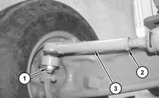
Illustration 2
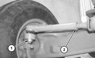
1. Loosen nut (1). Loosen nut (2).
g01155586
2. Use Tooling (A) in order to disconnect tie rod (3) from the steering knuckle. Remove nut (1). Remove tie rod (3).
Installation Procedure
Illustration 3
1. Install tie rod (3).
g01155609
2. Tighten nut (2). Install nut (1). Tighten nut (1) to a torque of 250 N·m (184 lb ft). Tighten nut (2) to a torque of 220 N·m (162 lb ft).
Copyright 1993 - 2025 Caterpillar Inc. All Rights Reserved. Private Network For SIS Licensees. Sat Feb 8 01:24:48 UTC+0700 2025
Product: BACKHOE LOADER
Model: 414E BACKHOE LOADER ELB
Configuration: 414E Backhoe Loader ELB00001-UP (MACHINE) POWERED BY 3054 Engine
Disassembly and Assembly
414E, 416E, 420E, 422E, 428E, 430E, 432E, 434E, 442E and 444E Backhoe Loaders Power Train
Media Number -RENR6475-13 Publication Date -01/07/2017 Date Updated -13/07/2017
Tie Rod (Steering)(Front) - Remove and Install
SMCS - 4318-010-ZH; 4318-010
Removal Procedure
Table 1
Required Tools
Tool Part Number
Part Description Qty
A 1P-2320 Combination Puller 1
Start By:
i05415863
a. Remove the front tires and rims. Refer to Disassembly and Assembly, "Tire and Rim (Front) -Remove and Install".
1 g01117258
Illustration
Illustration 2 g01117260
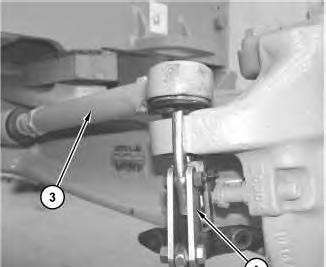
1. Loosen nut (1) from tie rod (2).
2. Use Tooling (A) in order to disconnect tie rod (2). Remove nut (1) and remove tie rod (2).
Installation Procedure
Illustration 3 g01117258
1. Install tie rod (2).
2. Install nut (1). Tighten nut (1) to a torque of 220 N·m (162 lb ft).
3. Tighten the end of tie rod (2) that fastens into the steering cylinder to a torque of 300 + 15 - 45 N·m (220 + 11 -33 lb ft)
End By:
a. Install the front tires and rims. Refer to Disassembly and Assembly, "Tire and Rim (Front)Remove and Install".
Product: BACKHOE LOADER
Model: 414E BACKHOE LOADER ELB
Configuration: 414E Backhoe Loader ELB00001-UP (MACHINE) POWERED BY 3054 Engine
Disassembly and Assembly
414E, 416E, 420E, 422E, 428E, 430E, 432E, 434E, 442E and 444E Backhoe Loaders Power Train
Steering Cylinder (Front) - Remove and Install
SMCS - 4303-010-FR
Removal Procedure
Table 1
Required Tools
Tool Part Number
Part Description Qty
A 1P-2320 Combination Puller 1
B 155-0695 Thread Lock Compound -
Start By:
i03664881
A. Remove the front axle. Refer to Disassembly and Assembly, "Drive and Steering Axle (Front) - Remove".
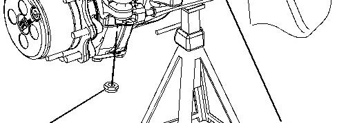
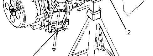
Illustration 1 g01117223
Illustration 2 g01117229
1. Place front axle assembly (2) onto suitable cribbing. Loosen nut (1) from each side.
2. Use Tooling (A) in order to disconnect tie rod (3) . Remove nut (1) and remove tie rod (3) . Repeat for the other side.
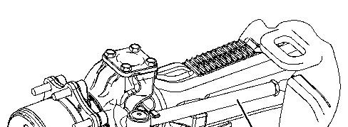
Illustration 3 g01117236
3. Remove bolts (4) and remove steering cylinder (5) .
Installation Procedure
Illustration 4 g01117236
1. Install steering cylinder (5) . Apply Tooling (B) to bolts (4) and install bolts (4) . Tighten bolts (4) to a torque of 460 N·m (340 lb ft).
Illustration 5 g01117229
2. Install tie rod (3) . Repeat for the other side.
3. Install nut (1) to each side of front axle assembly (2) . Tighten nut (1) to a torque of 220 N·m (162 lb ft).
End By: Install the front axle. Refer to Disassembly and Assembly, "Drive and Steering Axle (Front) - Install".
Copyright 1993 - 2025 Caterpillar Inc. All Rights Reserved. Private Network For SIS Licensees. Sat Feb 8 01:25:25 UTC+0700 2025
Product: BACKHOE LOADER
Model: 414E BACKHOE LOADER ELB
Configuration: 414E Backhoe Loader ELB00001-UP (MACHINE) POWERED BY 3054 Engine
Disassembly and Assembly
414E, 416E, 420E, 422E, 428E, 430E, 432E, 434E, 442E and 444E Backhoe Loaders Power Train
Steering Cylinder (Front) - Remove and Install - Two-Wheel Drive
SMCS - 4303-010-FR
Removal Procedure
Table 1
Required Tools
Tool Part Number
Part Description Qty
A 155-0695 Thread Lock Compound -
Start By:
A. Release the hydraulic system pressure. Refer to Disassembly and Assembly, "Hydraulic System Pressure - Release".
B. Remove the tie rods. Refer to Disassembly and Assembly, "Tie Rod (Steering) (Front)Remove".
Note: Put identification marks on all lines, on all hoses, on all wires, and on all tubes for installation purposes. Plug all lines, hoses, and tubes. This helps to prevent fluid loss and this helps to keep contaminants from entering the system.
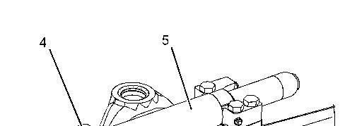
Illustration 1
g01238002
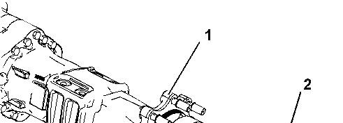
1. Disconnect hose assemblies (1) and (2) . Remove bolts (4) and steering cylinder (3) .
Installation Procedure
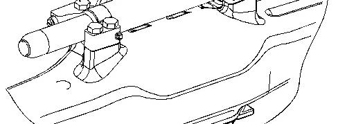
Illustration 2
g01238002
1. Install steering cylinder (3) and bolts (4) . Apply Tooling (A) to bolts (4) and install bolts (4) . Tighten bolts (4) to a torque of 460 N·m (340 lb ft). Connect hose assemblies (1) and (2) .
End By: Install the tie rods. Refer to Disassembly and Assembly, "Tie Rod (Steering) (Front)Install".
Copyright 1993 - 2025 Caterpillar Inc. All Rights Reserved. Private Network For SIS Licensees. Sat Feb 8 01:25:39 UTC+0700 2025
Product: BACKHOE LOADER
Model: 414E BACKHOE LOADER ELB
Configuration: 414E Backhoe Loader ELB00001-UP (MACHINE) POWERED BY 3054 Engine
Disassembly and Assembly
414E, 416E, 420E, 422E, 428E, 430E, 432E, 434E, 442E and 444E Backhoe Loaders Power Train
Final Drive Planetary - Remove
SMCS - 4050-011; 4084-011
Removal Procedure
Start By:
i02106590
a. Remove the wheel and tire. Refer to Disassembly and Assembly, "Wheel and Tire - Remove and Install".
NOTICE
Care must be taken to ensure that fluids are contained during performance of inspection, maintenance, testing, adjusting and repair of the product. Be prepared to collect the fluid with suitable containers before opening any compartment or disassembling any component containing fluids.
Refer to Special Publication, NENG2500, "Caterpillar Tools and Shop Products Guide" for tools and supplies suitable to collect and contain fluids on Caterpillar products.
Dispose of all fluids according to local regulations and mandates.
1. Drain the oil from the final drive planetary into a suitable container for storage or disposal. Refer to Operation and Maintenance Manual, "Final Drive Planetary (Axle) Oil - Change".
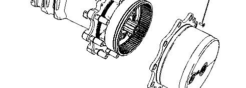
Illustration 1 g01072848
2. Remove screws (2) and remove planetary carrier assembly (3) from wheel flange (1).
Copyright 1993 - 2025 Caterpillar Inc. All Rights Reserved. Private Network For SIS Licensees. Sat Feb 8 01:25:52 UTC+0700 2025
This is the sample of the manual click on the download link for complete manual
For some reason if link does not work download this pdf and then click