

Note: Use Bookmarks panel to navigate

Product: EXCAVATOR
Model: 375-A EXCAVATOR 6NK
Configuration: 375 and 375 L Excavators 6NK00001-UP (MACHINE) POWERED BY 3406 Engine
Disassembly and Assembly
26SI Series Alternator Media
Alternator - Assemble
SMCS - 1405-016
Assembly Procedure
i01167078
Note: Cleanliness is an important factor. Before assembly, all parts should be thoroughly cleaned in cleaning fluid. Allow the parts to air dry. Wiping cloths or rags should not be used to dry parts. Lint may be deposited on the parts which may cause later trouble. Inspect all parts. If any parts are worn or damaged, use new parts for replacement.
Note: Do not strike the diodes. The shock of such an impact can damage the diodes. Use proper tools in order to press the diodes in the mountings.
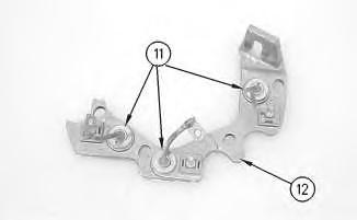
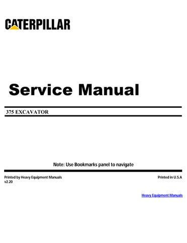
Illustration 1
1. Install 3 diodes (11) in heat sink (12) .
g00628072
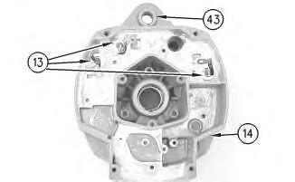
Illustration 2
g00628068
Note: Do not strike the bushing. Shocks from striking the housing can cause damage.
2. Press bushing (43) in housing (14) .
3. Install 3 diodes (13) in housing (14) .
Illustration 3
This is the sample of the manual click on the download link for complete manual
For some reason if link does not work download this pdf and then click

Illustration 4
g00628063
7. Press housing (31) on rotor (39) and bearing (40) .
8. Install 4 screws (38) in housing (31) .
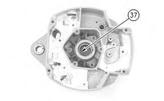
Illustration 5
g00628057
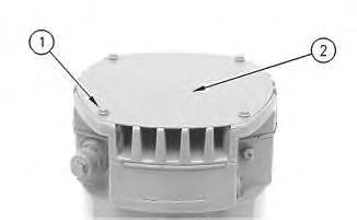
Note: Do not strike the bearing. Shocks from striking the housing can cause damage.
9. Install the inner race. Press bearing (37) into the housing.
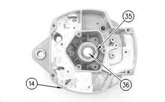
Illustration 6
10. Press cap (36) in housing (14) .
g00628043
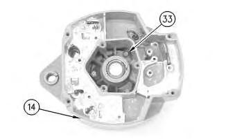
Illustration 7
g00628041
11. Install the coil and support (34) in housing (14). Guide the field leads and the grommet through the hole as the coil is installed in housing (14). Install 3 screws (33) .

Illustration 8
g00628037
12. Press the stator (32) and housing (14) together. Guide the stator leads and the grommet through the hole as the stator is installed in housing (14) .
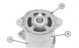
Illustration 9
g00628035
Note: Do not damage exposed stator windings or field windings. Bumping the windings or scraping the windings may break the insulation. Broken insulation may create a short circuit or a ground.
13. Join housing (31) and housing (14). Install 4 bolts (30) .
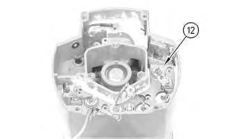
Illustration 10
g00627853
Note: Many of the alternator's internal components are covered with dielectric grease. If the grease is removed, reapply the grease.

11
14. Install Insulator (29). Install the heat sink and diode assembly (12) in housing (14) .

12
15. Install separator (28) .
16. Install alternator output terminal (27). Install insulator (26). Install the nut and washer (25) .
17. Install diode trio (24) and install screw (23) .
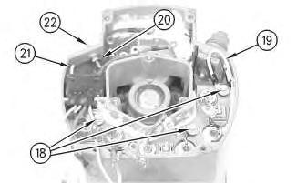
Illustration 13
g00627832
18. Install the 3 screws and insulators (18). Connect wire (19) .
19. If the "R" terminal is used, install the following components: nut (20), lead (21), the washer and terminal (21) .

Illustration 14
g00627820
20. Install the screw and insulator (16). Connect capacitor lead (17) .
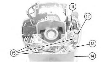
Illustration 15
g00627810
Note: The 3 output diodes (11) are located in heat sink (12). These diodes are identical in polarity. Diode (11) has red insulation on the wire. The 3 ground diodes (13) are located in housing (14). These diodes are identical in polarity. Diode (13) has black insulation on the wire.
21. Connect 6 diode leads. Connect 3 phase leads. Connect 3 stator phase leads. Install 3 nuts (15).
Table 1
Alternator Ground
Negative
Current Flow of the Output Diodes
Lead to the Heat Sink
Current Flow of the Ground Diodes
Housing to the Lead Red Wire Black Wire
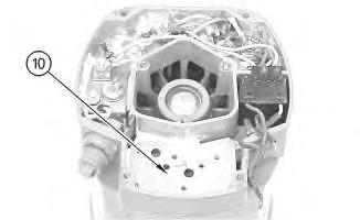
Illustration 16
22. Install mounting plate (10).
g00627808
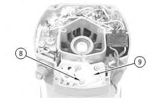
Illustration 17
23. Install regulator (9) .
24. Install grounded mounting screw (8) .
g00627804
18
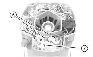
25. Install 2 insulated screws (6). Connect the 3 leads.
Note: The regulator and the mounting plate are coated with dielectric grease. If the grease is removed, reapply the grease.
26. Install nut (7) and connect the wire.
19
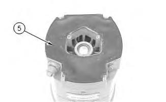
27. Install gasket (5) .
20
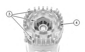
28. Position cover (4). Install 7 screws (3) .
21
29. Position plate (2). Install 4 screws (1) .
30. Install the fan, the pulley, the washer, and the pulley nut.
1993 - 2025 Caterpillar Inc.
Rights Reserved.
Network For SIS Licensees. Tue Apr 15 23:54:17 UTC+0700 2025
Product: EXCAVATOR
Model: 375-A EXCAVATOR 6NK
Configuration: 375 and 375 L Excavators 6NK00001-UP (MACHINE) POWERED BY 3406 Engine
Disassembly and Assembly
26SI Series Alternator
Alternator - Disassemble
SMCS - 1405-015
Disassembly Procedure
Table 1
Required Tools
Start By:
A. Remove the alternator. Refer to Disassembly and Assembly, "Alternator - Remove" for the machine that is being serviced.
Note: Cleanliness is an important factor. Before the disassembly procedure, the exterior of the component should be thoroughly cleaned. This will help to prevent dirt from entering the internal mechanism.
1. Remove the pulley nut, the washer, the pulley, and the fan.
Illustration 1
2. Remove 4 screws (1). Remove plate (2) .
Illustration 2
3. Remove 7 screws (3). Remove cover (4) .
Illustration 3
4. Remove gasket (5) .
Illustration 4
5. Remove 2 insulated screws (6). Remove the 3 leads.
Note: The regulator and the mounting plate are coated with dielectric grease. If the grease is removed, reapply the grease.
6. Remove nut (7) .
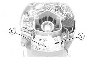
Illustration 5
7. Remove grounded mounting screw (8) .
8. Remove regulator (9) .

Illustration 6
g00627808
9. Remove mounting plate (10). The mounting plate may be stuck to the regulator.
Illustration 7
g00627810
Note: The 3 output diodes (11) are located in heat sink (12). These diodes are identical in polarity. Diode (11) has red insulation on the wire. The 3 ground diodes (13) are located in housing (14). These diodes are identical in polarity. Diode (13) has black insulation on the wire.
10. Remove 3 nuts (15). Disconnect 3 stator phase leads. Disconnect 3 phase leads. Disconnect 6 diode leads.
Table 2
Alternator Ground Current Flow of the Output Diodes Current Flow of the Ground Diodes
Negative
Lead to the Heat Sink Housing to the Lead Red Wire Black Wire
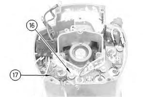
Illustration 8
g00627820
11. Remove the screw and insulator (16). Disconnect capacitor lead (17) .
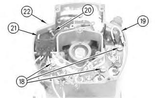
Illustration 9
g00627832
12. Remove the 3 screws and insulators (18). Disconnect wire (19) .
13. If the "R" terminal is used, remove the following components: nut (20), lead (21), the washer and terminal (21) .
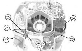
Illustration 10
14. Remove screw (23) and remove diode trio (24) .
15. Remove the nut and washer (25). Remove insulator (26). Remove alternator output terminal (27) .
16. Remove separator (28) .
Illustration 11
g00627853
Note: Many of the alternator's internal components are covered with dielectric grease. If the grease is removed, reapply the grease.
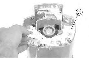
Illustration 12
g00627855
17. Remove the heat sink and diode assembly (12) from housing (14). Insulator (29) may be stuck to heat sink (12) .
Illustration 13
g00628035
Note: Do not damage exposed stator windings or field windings. Bumping the windings or scraping the windings may break the insulation. Broken insulation may create a short circuit or a ground.
18. Remove 4 bolts (30). Carefully separate housing (31) from housing (14) .
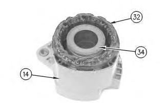
Illustration 14
g00628037
19. Pull apart stator (32) and housing (14). Guide the stator leads and the grommet through the hole as the stator is removed from housing (14) .
Illustration 15
g00628041
20. Remove 3 screws (33). Remove the coil and support (34) from housing (14). Guide the field leads and the grommet through the hole as the coil is removed from housing (14) .
Illustration 16
g00628043
21. Position a small screwdriver in slot (35). Pry cap (36) from housing (14) .
Illustration 17
g00628057
Note: Do not strike the bearing. Shocks from striking the housing can cause damage.
22. Wipe the excess grease from the bearing well. Press bearing (37) into the housing. Remove the inner race.
Illustration 18
23. Remove 4 screws (38) from housing (31) .
g00628063
24. Lift rotor (39) and bearing (40) from housing (31) .
Illustration 19
25. Pull bearing (40) from rotor (39) .
26. Pull retainer (41) from rotor (39) .
27. Pull collar (42) from rotor (39) .
g00628067
Illustration 20
g00628068
Note: Do not strike the bushing. Shocks from striking the housing can cause damage.
28. Press bushing (43) from housing (14) .
Note: Do not strike the diodes. The shock of such an impact can damage the diodes. Use proper tools in order to press or pull the diodes from the mountings. As much as 890 N (200 lb) of force may be needed to remove a diode.
29. Remove 3 diodes (13) from housing (14) .
Illustration 21
30. Remove diode (11) from heat sink (12) .
g00628072
Copyright 1993 - 2025 Caterpillar Inc. All Rights Reserved. Private Network For SIS Licensees.
Tue Apr 15 23:54:00 UTC+0700 2025

Product: EXCAVATOR
Model: 375-A EXCAVATOR 6NK
Configuration: 375 and 375 L Excavators 6NK00001-UP (MACHINE) POWERED BY 3406 Engine
Disassembly and Assembly
Flexxaire Fan
Media Number -RENR3699-07
Control System - Remove and Install
SMCS - 1356-010-YC
General Installation
Installation of the Mark I Control System

i01739978
Illustration 1 g00564778
Mark I Control System
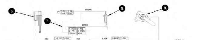
(1) Mark I control box (2) AUTO-purge timer (3) Cable for remote display (4) Remote display (5) Pigtail
(6) Actuator
(7) Temperature and ground cable
(8) Temperature sensor
(9) Position sensor
(10) Power cable
1. Mount control box (1) in the operator's compartment. The mounting location should meet the following criteria:
Minimal debris and vibration
Safe from water that is high pressure
Accessible for future adjustments or changes in setup
The control box should be mounted in a vertical position, and vibration mounts that are supplied with the controller should be installed.
2. AUTO-purge timer (2) is located near control box (1). Connect the end of the cable for AUTO-purge timer (2) to the plug end of the cable for the AUTO-purge timer on control box (1).
3. Cable for remote display (3) may not be required for all installations. Connect the end of the cable for remote display (3) to the plug end of AUTO-purge timer (2). Connect the plug end of cable for remote display (3) into the end of the pigtail for remote display (4).
4. Mount remote display (4) on the dash or another convenient location. The remote display should be visible and accessible to the operator. Connect the end of the cable for remote display (4) to the plug end of the cable for remote display (3).
5. Connect the end of pigtail (5) to the plug end of the cable for control box (1). Pigtail (5) splits into a harness with three connectors. One end goes to actuator (6). One end goes to temperature sensor (8). One end goes to position sensor (9).
6. The following steps are for installation of actuator (6):
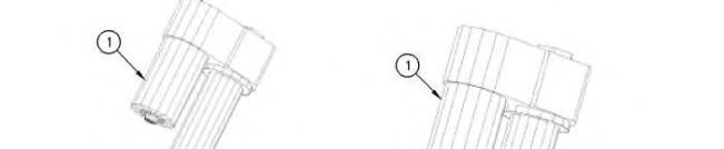
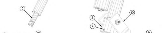
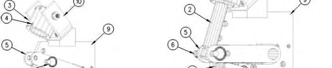
Illustration 2 g00592444
(1) Actuator
(2) Actuator rod
(3) Actuator collar
(4) Setscrew
(5) Operator fork
(6) Hitch pin
(7) Mechanical stop (8) Position sensor (9) Alignment plate (10) Actuator clevis
a. Remove hitch pin (6).
b. Position operator fork (5) against mechanical stop (7).
c. Manually turn actuator rod (2) outward until the rod is fully extended. When the rod reaches the end of travel, the actuator motor can be felt turning.
d. Retract actuator rod (2) by the rotating actuator rod by 180 degrees. The actuator motor should not turn.
e. Slide actuator (1) through actuator collar (3). Verify that the actuator collar is oriented so that setscrews (4) are facing away from actuator clevis (10).
f. Retracting actuator rod (2) by 1/4 turn may be required in order to line up the hole in actuator rod (2) with the hole in operator fork (5).
g. Insert hitch pin (6) through operator fork (5) and actuator rod (2).
h. Verify that operator fork (5) is against mechanical stop (7). Make sure that the actuator motor is oriented in the correct position. The actuator motor must be clear of obstructions. Rotate the actuator in the collar prior to tightening setscrews (4).
i. Apply 9S-3263 Thread Lock Compound to setscrews (4) and install the setscrews. Tighten the setscrew to a torque of 16 N·m (12 lb ft).
Note: Do not tighten setscrews more than 1.5 threads below the surface.
j. Connect the end of the cable for the actuator to the red and yellow plug of pigtail (5).
7. Connect the end of temperature and ground cable (7) to the plug with green and black wires of pigtail (5). The ground wire (green) is secured with a bolt that threads in to the support arm of the fan assembly. The brown lead wire is connected to the top of temperature sensor (8).
8. Thread temperature sensor (8) into the engine block. An area that is close to the water temperature regulator is recommended. Temperature sensor (8) comes with three thread adapters. The brown lead wire of temperature and ground cable (7) connects to the top of temperature sensor (8).
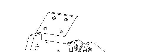
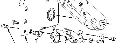
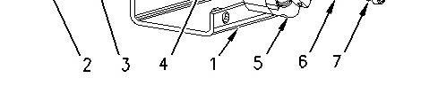
Illustration 3
(1) Mounting bracket for the position sensor (2) Bolt (3) Alignment plate (4) Mounting nut for the position sensor (5) Position sensor (6) Washer (7) Capscrew
9. The following steps are for installation of position sensor (9):
g00918804
a. Place mounting bracket (1) for the position sensor against alignment plate (3).
b. Thread bolt (2) into mounting nut (4) for the position sensor through alignment plate (3) and position sensor mounting bracket (1). Tighten bolt (2) to a torque of 16.3 N·m (12.0 lb ft).
c. Place position sensor (5) in the correct location.
d. Put washer (6) on capscrew (7). Thread capscrew (7) into mounting nut (4) for the position sensor through position sensor (5).
e. Connect the plug end of the cable for position sensor (5) to the end of the pigtail.
10. Connect the plug end of power cable (10) to the end of the power cable for the control box.
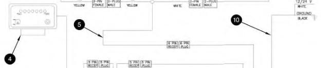
White wire - This wire connects to a 10 Amp fuse or to a circuit breaker. The power source that is being used must allow power to the control box when the engine is not running.
Black wire - This wire connects to the main disconnect or a different ground location.
Installation of the Mark III Control System
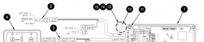
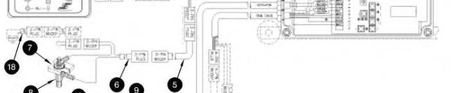
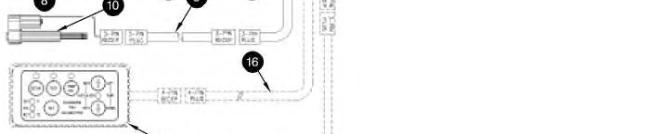
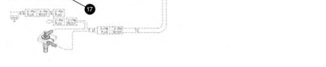
Illustration 4
Mark III control system
(1) Mark III control box
(2) Power cable
(3) Extension cable for remote display
(4) Remote display
(5) Extension cable for temperature sensor
(6) Cable for temperature sensor
(7) Ground collar
(8) Temperature sensor
(9) Extension cable for actuator
(10) Actuator
(11) Screw
(12) Mounting bracket
(13) Vibration mount
(14) Washer
g00573394
This is the sample of the manual click on the download link for complete manual
For some reason if link does not work download this pdf and then click