

This is the sample of the manual click on the download link for complete manual
This is the sample of the manual click on the download link for complete manual
For some reason if link does not work download this pdf and then click

Product: CHALLENGER
Model: 35 CHALLENGER 8DN
Configuration: Challenger 35 and Challenger 45 Agricultural Tractors 8DN00001-00849 (MACHINE) POWERED BY 3116 Engine
Disassembly and Assembly
3114, 3116, and 3126 Engines for Caterpillar Built Machines
Media Number -SENR3611-20 Publication Date -01/03/2019 Date Updated -19/03/2019
SMCS - 1063-012
Installation Procedure Table 1
Required Tools
Tool Part Number Part Description Qty
A - Loctite Gasket Sealant No.2B - Loctite C5-A Copper Anti-Seize -
NOTICE
Keep all parts clean from contaminants.
Contaminants may cause rapid wear and shortened component life.
Note: Use a new gasket to install the aftercooler.
i06818876
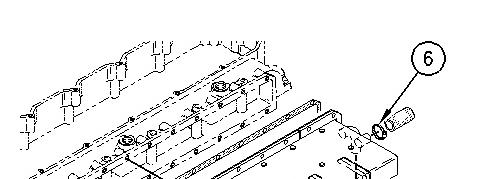


Illustration 1 g00746356
Note: Apply Tooling (A) to the threads of the bottom bolts before installation.
1. Install gasket (9) on the engine. Install aftercooler (10). Install bolts (8).
2. Tighten clamp (6) and tighten clamp (7).
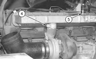
Illustration 2 g00746355
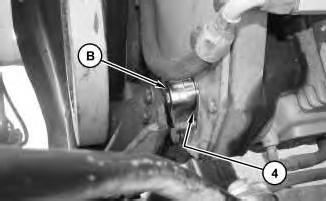
3. Tighten clamp (4).
4. Connect coupling (5).
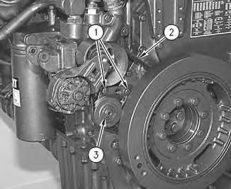
Illustration 3
g00508837
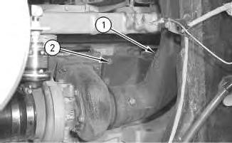
Illustration 4
g00508835
Note: Apply Tooling (B) to the threads of the exhaust elbow bolts.
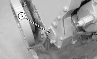
5. Install exhaust elbow (1) and exhaust pipe (3). Install bolts (2).
6. Fill the cooling system. Refer to Operation and Maintenance Manual, SEBU7098, "Cooling System Level - Check" for the correct procedure.
Copyright 1993 - 2024 Caterpillar Inc. All Rights Reserved. Private Network For SIS Licensees. Sat May 4 12:28:09 UTC+0530 2024
Product: CHALLENGER
Model: 35 CHALLENGER 8DN
Configuration: Challenger 35 and Challenger 45 Agricultural Tractors 8DN00001-00849 (MACHINE) POWERED BY 3116 Engine
Disassembly and Assembly
3114, 3116, and 3126 Engines for Caterpillar Built Machines
Media Number -SENR3611-20 Publication Date -01/03/2019 Date Updated -19/03/2019
Aftercooler - Remove
SMCS - 1063-011
Removal Procedure Table 1 Required Tools
NOTICE
Keep all parts clean from contaminants.
Contaminants may cause rapid wear and shortened component life.
NOTICE
Care must be taken to ensure that fluids are contained during performance of inspection, maintenance, testing, adjusting, and repair of the product. Be prepared to collect the fluid with suitable containers before opening any compartment or disassembling any component containing fluids.
Refer to Special Publication, NENG2500, "Dealer Service Tool Catalog" for tools and supplies suitable to collect and contain fluids on Cat products.
Dispose of all fluids according to local regulations and mandates.
At operating temperature, the engine coolant is hot and under pressure.
Steam can cause personal injury.
Check the coolant level only after the engine has been stopped and the fill cap is cool enough to touch with your bare hand.
Remove the fill cap slowly to relieve pressure.
Cooling system conditioner contains alkali. Avoid contact with the skin and eyes to prevent personal injury.
Note: Put identification marks on all hose assemblies, on all wires, and on all tube assemblies for installation purposes. Plug all hose assemblies and tube assemblies. This helps to prevent fluid loss and this helps to keep contaminants from entering the system.
1. Drain the coolant from the cooling system into a suitable container for storage or disposal.
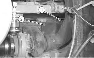
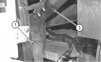
Illustration 2 g00508837
2. Remove bolts (2). Remove exhaust elbow (1) and exhaust pipe assembly (3).
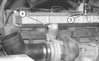
Illustration 3 g00746355
3. Loosen clamp (4).
4. Disconnect coupling (5).
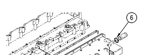


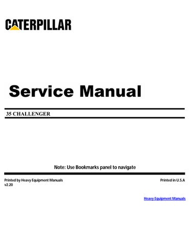
Illustration 4 g00746356
5. Loosen clamps (6) and (7).
6. Remove two top bolts (8) and install Tooling (A). Remove remaining bolts (8). Remove aftercooler (10).
7. Remove gasket (9) from aftercooler (10).
Copyright 1993 - 2024 Caterpillar Inc. All Rights Reserved. Private Network For SIS Licensees. Sat May 4 12:27:50 UTC+0530 2024
Product: CHALLENGER
Model: 35 CHALLENGER 8DN
Configuration: Challenger 35 and Challenger 45 Agricultural Tractors 8DN00001-00849 (MACHINE) POWERED BY 3116 Engine
Disassembly and Assembly
3114, 3116, and 3126 Engines for Caterpillar Built Machines
Media Number -SENR3611-20 Publication Date -01/03/2019 Date Updated -19/03/2019
SMCS - 1803-010
Removal Procedure
Do not disconnect the air lines until the air pressure in the system is at zero. If hose is disconnected under pressure it can cause personal injury.
NOTICE
Keep all parts clean from contaminants.
Contaminants may cause rapid wear and shortened component life.
NOTICE
Care must be taken to ensure that fluids are contained during performance of inspection, maintenance, testing, adjusting, and repair of the product. Be prepared to collect the fluid with suitable containers before opening any compartment or disassembling any component containing fluids.
Refer to Special Publication, NENG2500, "Dealer Service Tool Catalog" for tools and supplies suitable to collect and contain fluids on Cat products.
Dispose of all fluids according to local regulations and mandates.
1. Remove the air pressure from the air tank and drain the coolant from the cooling system.
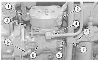
Illustration 1
Typical example
g00484206
2. Disconnect hose assemblies (1), (2) and (9) from the air compressor. Remove tube assembly (4) from the air compressor.
3. Remove bolt (5) and the washer. Remove clamp (7) from tube assembly for the breather. Move the tube assembly for the breather aside.
4. Remove bolts (3) and the washers that hold the air compressor to the timing gear housing.
5. Remove bolts (6) and remove air compressor (8) and the gasket from the engine.
Installation Procedure
Table 1
Required Tools
Tool Part Number Part Description Qty
A 4C-4030 Thread Lock Compound 1
NOTICE
Keep all parts clean from contaminants. Contaminants may cause rapid wear and shortened component life.
Note: Check the condition of the gaskets and O-ring seals. If gaskets or O-ring seals are damaged, use new parts for replacement.
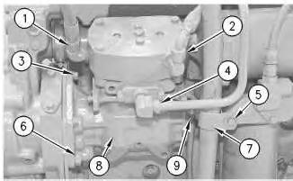
Illustration 2
Typical example
g00484206
1. Use bolts (3) and the washers to install air compressor (8). Apply Tooling (A) to the threads of bolts (6). Torque bolts (6) to 160 ± 30 N·m (118 ± 22 lb ft).
2. Install clamp (7) for the tube assembly for the breather with bolt (5) and the washer.
3. Install tube assembly (4) and connect hose assemblies (9), (2) and (1) to air compressor (8).
Copyright 1993 - 2024 Caterpillar Inc. All Rights Reserved.
Private Network For SIS Licensees.
Sat May 4 12:46:38 UTC+0530 2024
Product: CHALLENGER
Model: 35 CHALLENGER 8DN
Configuration: Challenger 35 and Challenger 45 Agricultural Tractors 8DN00001-00849 (MACHINE) POWERED BY 3116 Engine
Disassembly and Assembly
3114, 3116, and 3126 Engines for Caterpillar Built Machines
Media Number -SENR3611-20 Publication Date -01/03/2019 Date Updated -19/03/2019
SMCS - 1803-010-GE
Removal Procedure Table 1
Required Tools
Tool Part Number Part Description Qty A 1P-2320 Combination Puller 1
B 9S-1730 Socket 1
Start By:
a. Remove the air compressor.
NOTICE
Keep all parts clean from contaminants.
Contaminants may cause rapid wear and shortened component life.
i05024711
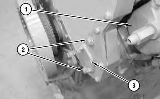
Illustration 1
g03196216
1. Temporarily install air compressor (1) with bolts (2). Remove cover plate (3).
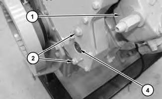
Illustration 2
g03196337
2. Loosen nut (2). Remove bolts (2) and remove air compressor (1).
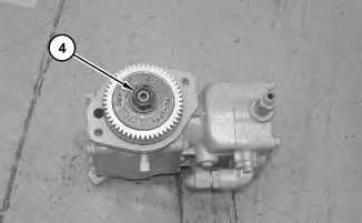
Illustration 3
3. Remove nut (4).
g03196436
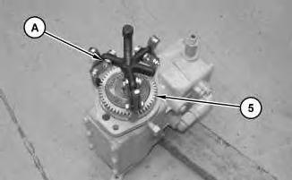
Illustration 4
g03196416
4. Use Tooling (A) in order to remove gear (5).
Installation Procedure
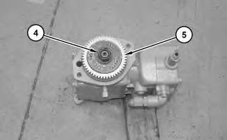
Illustration 5
g03196438
1. Clean the inside diameter of gear (5) and the shaft. Lube the washer and the shaft thread with engine oil. Position drive gear (5) on the air compressor, and install the washer and nut (4). Tighten nut (4) hand tight.
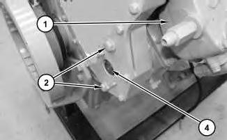
Illustration 6
g03196337
2. Install air compressor (1) and bolts (2). Keep the engine from turning and tighten nut (4) to a torque of 170 ± 15 N·m (125 ± 11 lb ft)
7
3. Install Tooling (B) onto nut (4) and tap one time a hammer.
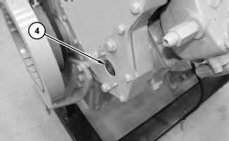
Illustration 8
4. Keep the engine from turning and tighten nut (4) to a torque of 170 ± 15 N·m (125 ± 11 lb ft)
9
5. Install cover plate (3).
a. Install the air compressor.
Copyright 1993 - 2024 Caterpillar Inc. All Rights Reserved.
Private Network For SIS Licensees. Sat May 4 12:46:53 UTC+0530 2024
Product: CHALLENGER
Model: 35 CHALLENGER 8DN
Configuration: Challenger 35 and Challenger 45 Agricultural Tractors 8DN00001-00849 (MACHINE) POWERED BY 3116 Engine
Disassembly and Assembly
3114, 3116, and 3126 Engines for Caterpillar Built Machines
Media Number -SENR3611-20 Publication Date -01/03/2019 Date Updated -19/03/2019
i01930386
Alternator - Remove and Install
SMCS - 1405-010
Removal Procedure Table 1 Required Tools
Tool Part Number Part Description Qty A 168-0383 Circuit Breaker Bar 1
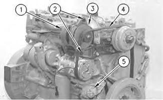
Illustration 1
Typical Example
g00609523
Note: Release the tension on the belt at the belt tightener, if the engine is not equipped with a belt tensioner.
1. Use Tooling (A) to release the tension on belt tensioner (5).
2. Remove drive belt (4) from the drive pulley on alternator (3).
3. Place an index mark on the wires of harness assembly (1) that are connected to the alternator. Disconnect harness assembly (1) from the alternator.
4. Remove bolts (2).
5. Remove alternator (3) from the mounting bracket.
Installation Procedure
Table 2
Required Tools Tool Part
A 168-0383 Circuit Breaker Bar 1
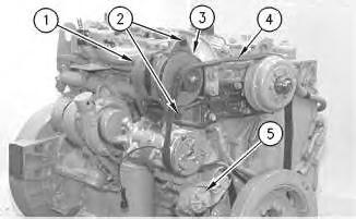
Illustration 2
Typical example
g00609523
1. Position alternator (3) on the mounting bracket. Install bolts (2).
2. Use Tooling (A) to install drive belt (4) on the drive pulley of the alternator.
Note: Adjust the tension on the drive belt if the engine is not equipped with a belt tensioner. Refer to the Operation and Maintenance Manual for the correct adjusting procedure.
3. Connect harness assembly (1) to the alternator. Use the index marks to correctly connect the harness assembly. Tighten the mounting bolt for the ground wire to a torque of 6.2 ± 0.6 N·m (54 ± 5 lb in). Tighten the mounting bolt for the battery wire to a torque of 11.3 ± 2.3 N·m (100 ± 20 lb in).
Product: CHALLENGER
Model: 35 CHALLENGER 8DN
Disassembly and Assembly
3114, 3116, and 3126 Engines for Caterpillar Built Machines
SMCS - 1203-535; 1219-535
Measurement Procedure
Table 1
Required Tools
Plastic Gauge (Green)
to 0.076 mm (0.001 to 0.003 inch)
Plastic Gauge (Red)
to 0.152 mm (0.002 to 0.006 inch)
Plastic Gauge (Blue)
to 0.229 mm (0.004 to 0.009 inch)
Plastic Gauge (Yellow) 0.230 to 0.510 mm (0.009 to 0.020 inch)
Note: Plastic gauge may not be necessary when the engine is in the chassis.
NOTICE
Keep all parts clean from contaminants.
Contaminants may cause rapid wear and shortened component life.
i05977048
Note: Cat does not recommend the checking of the actual bearing clearances particularly on small engines. This is because of the possibility of obtaining inaccurate results and the possibility of damaging the bearing or the journal surfaces. Each Cat engine bearing is quality checked for specific wall thickness.
Note: The measurements should be within specifications and the correct bearings should be used. If the crankshaft journals and the bores for the block and the rods were measured during disassembly, no further checks are necessary. However, if the technician still wants to measure the bearing clearances, Tooling (A) is an acceptable method. Tooling (A) is less accurate on journals with small diameters if clearances are less than 0.10 mm (0.004 inch).
Lead wire, shim stock or a dial bore gauge can damage the bearing surfaces.
The technician must be very careful to use Tooling (A) correctly. The following points must be remembered:
• Ensure that the backs of the bearings and the bores are clean and dry.
• Ensure that the bearing locking tabs are properly seated in the tab grooves.
• The crankshaft must be free of oil at the contact points of Tooling (A).
1. Put a piece of Tooling (A) on the crown of the bearing that is in the cap.
Note: Do not allow Tooling (A) to extend over the edge of the bearing.
2. Use the correct torque-turn specifications in order to install the bearing cap. Do not use an impact wrench. Be careful not to dislodge the bearing when the cap is installed.
Note: Do not turn the crankshaft when Tooling (A) is installed.
3. Carefully remove the cap, but do not remove Tooling (A). Measure the width of Tooling (A) while Tooling (A) is in the bearing cap or on the crankshaft journal. Refer to Illustration 1.
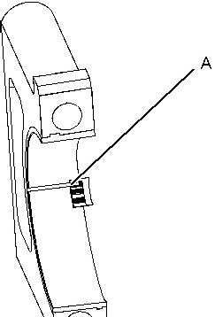

Illustration 1 g01152855
Typical Example
4. Remove all of Tooling (A) before you install the bearing cap.
Note: When Tooling (A) is used, the readings can sometimes be unclear. For example, all parts of Tooling (A) are not the same width. Measure the major width in order to ensure that the parts are within the specification range. Refer to Specifications Manual, "Connecting Rod Bearing Journal" and Specifications Manual, "Main Bearing Journal" for the correct clearances.
Copyright 1993 - 2024 Caterpillar Inc. All Rights Reserved. Private Network For SIS Licensees. Sat May 4 12:42:28 UTC+0530 2024
Product: CHALLENGER
Model: 35 CHALLENGER 8DN
Configuration: Challenger 35 and Challenger 45 Agricultural Tractors 8DN00001-00849 (MACHINE) POWERED BY 3116 Engine
Disassembly and Assembly
3114, 3116, and 3126 Engines for Caterpillar Built Machines
Media Number -SENR3611-20 Publication Date -01/03/2019 Date Updated -19/03/2019
SMCS - 1358-010
Removal Procedure
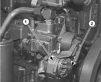
Illustration 1 g01011962
1. Use a breaker bar to release the tension on belt tensioner (1). Remove the drive belt.
2. Remove bolt (2) and belt tensioner (1).
Installation Procedure
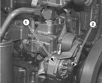
Illustration 2
1. Position belt tensioner (1) on the cylinder block. Install bolt (2).
2. Install the drive belt. Use a breaker bar to release tension on belt tensioner (1).
Copyright 1993 - 2024 Caterpillar Inc. All Rights Reserved. Private Network For SIS Licensees. Sat May 4 12:44:57 UTC+0530 2024
Product: CHALLENGER
Model: 35 CHALLENGER 8DN
Configuration: Challenger 35 and Challenger 45 Agricultural Tractors 8DN00001-00849 (MACHINE) POWERED BY 3116 Engine
Disassembly and Assembly
3114, 3116, and 3126 Engines for Caterpillar Built Machines
Media Number -SENR3611-20
Publication Date -01/03/2019
SMCS - 1358-012
Installation Procedure
Date Updated -19/03/2019
Illustration 1 g00619355
1. Position water pump belt tightener (3) and install V-belt (2) on the pulley of water pump belt tightener (3).
2. Install bolts (1) that hold water pump belt tightener (3) to the timing gear housing.
3. Adjust the tension of V-belt (2). Refer to Operation and Maintenance Manual, "Belt Tension Chart". Sat May 4 12:45:55 UTC+0530 2024
This is the sample of the manual click on the download link for complete manual
For some reason if link does not work download this pdf and then click