DOWNLOAD LINK
For some reason if link does not work download this pdf and then click
Product: MARINE ENGINE
Model: 3516B MARINE ENGINE 4BW
Configuration: 3516B Marine Long Stroke Engine 4BW00001-UP
Operation and Maintenance Manual
Customer Communication Module (CCM) for Diesel Engines
Communication Initialization
SMCS - 1926
The CCM may be connected directly to the host equipment. The CCM may also be connected to the equipment by using modems. The initialization procedure depends on the type of connection. The correct initialization procedure is necessary for proper communication between the CCM and the equipment.
When modems are installed between the CCM and the host equipment, the complexity of the communication network is increased. The RS-232C ports must be set to the proper parameters for communication on the following equipment: host equipment, modems and CCM. The phone line ports of the modems must be compatible. To connect the modems, consult the manufacturer's instructions.
Copyright 1993 - 2025 Caterpillar Inc. All Rights Reserved. Private Network For SIS Licensees. Sat Feb 15 00:58:20 UTC+0530 2025
i01200873
Product: MARINE ENGINE
Model: 3516B MARINE ENGINE 4BW
Configuration: 3516B Marine Long Stroke Engine 4BW00001-UP
Operation and Maintenance Manual
Customer Communication Module (CCM) for Diesel Engines
-SEBU6874-04
Data Link Guidelines
SMCS - 1926
The CCM has the ability to communicate with a maximum of eight other controllers. The number of available connections will depend on the type of device that is being connected. Generator set applications are limited to eight controllers that can be connected to the CCM. Marine applications are limited to a maximum of three connections.
The CCM identifies different controllers on the data link by the Module Identifier (MID) of the controller. The MID is programmable in some cases. Refer to the Operations and Maintenance Manual, "Engine Number - Program" for more detailed information on programming the Module Identifiers. Each controller that is connected to the CCM must have a unique MID.
There are two versions of Electronic Control Modules (ECM) for 3500B EUI Engines. The connection to the CCM will depend on the version of the ECM. The version of the ECM is based on the serial number of the engine. The serial number is listed on the engine nameplate. Use the following chart to determine the correct version of controller for each engine.
Table 1
Serial Numbers
Version C
Version D
N/A 1NW00001 & Up
N/A 1PW00001 & Up
N/A 1TW00001& Up
2BM00001 to 2BM00122 2BM00123 & Up
N/A 2FW00001 & Up
N/A 2GW00001 & Up
N/A 2HW00001 & Up
N/A 3CW00001 & Up
3DM00001 to 3DM00092 3DM00093 & Up
N/A
3DW00001 & Up
N/A 4AW00001 & Up
4GM00001 to 4GM00211 4GM00212 & Up
4TN00001 to 4TN00095 4TN00096 & Up
6HN00001 to 6HN00155 6HN00156 & Up
6PN00001 to 6PN00284 6PN00285 & Up
6WN00001 to 6WN00134 6WN00135 & Up
7HM00001 to 7HM00173 7HM00174 & Up
7RN00001 to 7RN00462 7RN00463 & Up
7SM00001 to 7SM00076 7SM00077 & Up
8CN00001 to 8CN00143 8CN00144 & Up
8EM00001 to 8EM00257 8EM00258 & Up
8KN00001 to 8KN00142 8KN00143 & Up
8RM00001 to 8RM00199 8RM00200 & Up
9AN00001 to 9AN00120 9AN00121 & Up
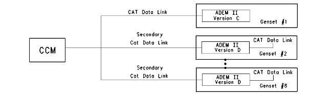
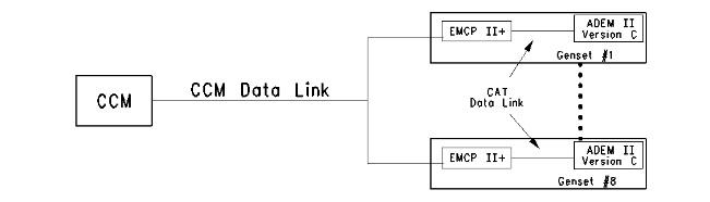
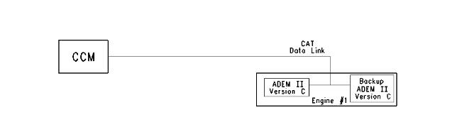
• Version C of the ADEM II controller (ECM) has a primary data link for use with the CCM. This data link is called the CAT Data Link. The Module Identifier (MID) of this controller is a fixed value. Each controller on the CAT Data Link must have a unique MID. The CCM can only be connected to one Version C ECM on the CAT Data Link.
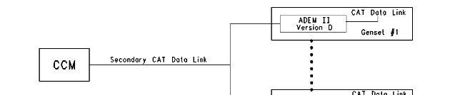
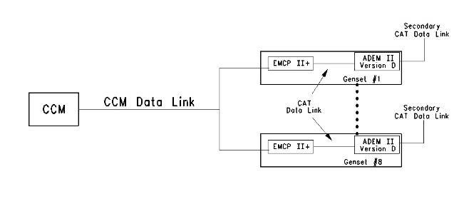
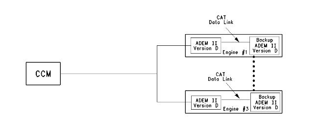
• Version D of the ADEM II controller (ECM) also has a primary data link for use with the CCM. The value of the MID for the primary data link is fixed. Version D also has a secondary data link for use with the CCM. The Secondary CAT Data Link has a programmable MID. A maximum of eight different values is available for generator set applications. A maximum of three different values is available for marine applications.
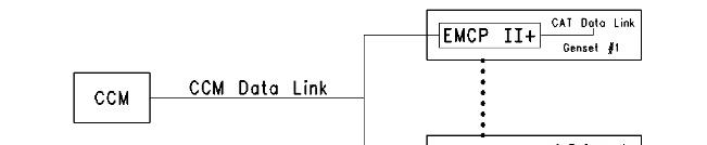
• EMCP II (basic model) has a primary data link for use with the CCM. This data link is called the CAT Data Link. The CAT Data Link has a programmable MID. A maximum of eight different values may be used for the MID.
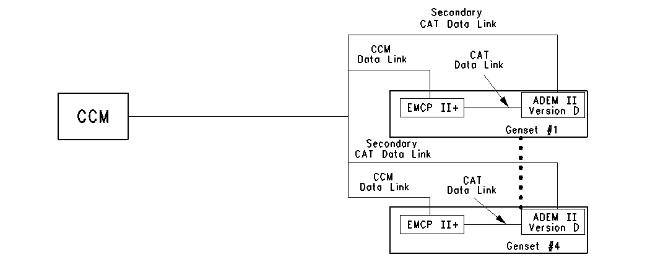
• EMCP II+ has the same primary data link as EMCP II (CAT Data Link) with a programmable value for the MID. The EMCP II+ also has a secondary data link for use with the CCM. The CCM Data Link has a programmable value for the MID. The CAT Data Link and the CCM Data Link have eight MID values.
• The Secondary CAT Data Link and the CCM Data Link can be treated in the same manner on the 3500B Version D and the EMCP II+ applications.
• There is a maximum of one CCM per data link.
• There is a maximum of one CCM per engine.
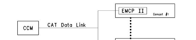
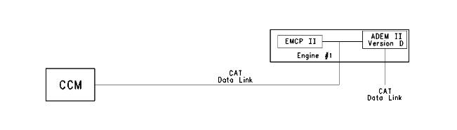
The previous descriptions govern the connections between the devices and the CCM. When an ADEM II controller and an EMCP II or EMCP II+ controller are connected, the CAT Data Link is
always used for the connections. All subsequent connections to the CCM (ADEM II Version D or EMCP II+) are made by using the secondary data link. The following examples will illustrate some valid CCM connections with multiple electronic controllers. These examples are only a representation of most possible valid connections or combinations.
1
MUI Generator sets with EMCP II (Basic Model)
2
MUI Generator sets with EMCP II+
Illustration 3
3500B EUI Generator set (Version C ECM)
Illustration
g00649118
Illustration
g00649133
g00649182
Illustration 4 g00649184
3500 B EUI Generator sets (Version D ECM)
Illustration 5 g00649192
3500B EUI Generator sets (Version C and D ECM's)
For the application that is shown in Illustration 5, only one Version C ECM is allowed.
Illustration 6 g00649200
3500B EUI Generator set (Version C ECM) with EMCP II (Basic Model)
Illustration 7 g00649317
EMCP II Basic and 3500B EUI Generator set (Version D ECM)
One CCM is required for each engine with Version D ECM.
Illustration 8
3500B EUI Generator sets (Version C ECM) with EMCP II+
g00649214
Illustration 9 g00649236
3500B EUI Generator sets (Version D ECM) with EMCP II+
Illustration 10 g00649243
3500B EUI Generator sets (Version D ECM) with EMCP II+
A maximum of four generator sets can be connected in the application that is shown in Illustration 10. The CCM is limited to eight connections. In Illustration 9, eight generator sets can be connected. More detailed information can be obtained from the ADEM II controller in Illustration 10, but only four generator sets can be connected.
Illustration 11
3500B EUI Marine Engine (Version C ECM)
One CCM is required for each engine with a Version C ECM.
g00649268
12
3500B EUI Marine Engine (Version D ECM)
Copyright 1993 - 2025 Caterpillar Inc. All Rights Reserved. Private Network For SIS Licensees. Sat Feb 15 00:57:55 UTC+0530 2025
Illustration
Product: MARINE ENGINE
Model: 3516B MARINE ENGINE 4BW
Configuration: 3516B Marine Long Stroke Engine 4BW00001-UP
Operation and Maintenance Manual
Customer Communication Module (CCM) for Diesel Engines Media
-01/03/2000
Display Description
SMCS - 1926
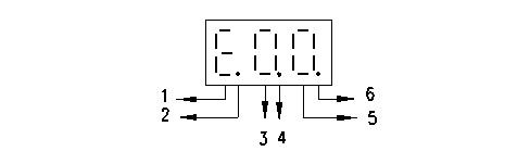
The CCM display indicates the status of the CAT Data Link and the RS-232C during normal operation. The CCM will also display some of the current parameters for communication.
Illustration 1 g00656709
(1) Error code
(2) Activity on CAT Data Link
(3) First digit of error code
(4) The CCM is transmitting on RS 232C.
(5) Second digit of error code
(6) The CCM is receiving data on the RS 232C.
The values E, 0, and 0 indicate an error code of 00. The code E00 means that no faults are present, and the CCM is in normal operating mode. The complete list of error codes are in the Operation and Maintenance Manual, "Troubleshooting" section. The periods on the display will flash when information is transmitted on the CAT Data Link. The periods on the display will flash when
i01225209
information is transmitted on the RS-232C port. No period indicates that no activity is taking place.
Note: Units with the part number 117-6170 Customer Communication Module will display the faults that have been logged. Each fault will be displayed for 2 seconds in 60 second intervals. This flashing fault log will not appear for any other version of CCM. The fault log can be cleared by using the PC software for the CCM.
CCM Power Up Display
The CCM display will perform a lamp test (8.8.8.). The parameters for communication protocol (n81 9600 E00) will be displayed next. An example of the power up sequence is given below:
Table 1
8.8.8. n81 9600 E00
8.8.8. All of the segments are turned on for a two second lamp test.
n81 n 8 1 No parity (default value)
Eight data bits (default value) One stop bit (default value)
9600 Rate of Communication (default value)
E00 Error Code No faults are present.
The values for communication can be changed by using a host device or by using the PC software for the CCM. Refer to "Caterpillar CCM PC For Windows: Getting Started Manual". The values for communication must match the values for the modems (if used) and the values for the host device.
Copyright 1993 - 2025 Caterpillar Inc. All Rights Reserved. Private Network For SIS Licensees.
Sat Feb 15 00:56:27 UTC+0530 2025
Product: MARINE ENGINE
Model: 3516B MARINE ENGINE 4BW
Configuration: 3516B Marine Long Stroke Engine 4BW00001-UP
Operation and Maintenance Manual
Customer Communication Module (CCM) for Diesel Engines Media Number -SEBU6874-04
General Installation Requirements
SMCS - 1926
When a CCM is installed, the following specifications must be met:
• environmental
• mounting
• wire and cable
The connection diagrams must be followed. Improper wiring may cause erratic operation of the CCM. If modems are used, the user must set up the modems properly. Copyright 1993 - 2025 Caterpillar Inc. All Rights Reserved. Private Network For SIS Licensees.
i01201862
Product: MARINE ENGINE
Model: 3516B MARINE ENGINE 4BW
Configuration: 3516B Marine Long Stroke Engine 4BW00001-UP
Operation and Maintenance Manual
Customer Communication Module (CCM) for Diesel Engines
General Operation
SMCS - 1926
The Customer Communication Module (CCM) provides a communication link between the electronic control system and a host device. An operator has the capability to control the engine remotely with the host device. The operator can monitor the engine remotely. The operator can program the engine remotely. 3500B Marine applications cannot be controlled remotely.
The host device can be one of the following items:
• personal computer (PC)
• Programmable Logic Controller (PLC)
• any other device with an RS-232C port
The host device can be connected directly to the CCM. The communication link is established with the CAT Data Link and the industry standard RS-232C cable. The host device can also be used with a modem.
If the host device is a PC, software that is compatible with the CCM is available from Caterpillar. Refer to "Caterpillar CCM PC For Windows: Getting Started Manual" for more information on the PC software.
The CCM can be used with customized software. A serial data format is used to aid in programming a PLC to communicate with the CCM. Refer to the Operation and Maintenance Manual, "Communication Protocol for Customized Systems".
Copyright 1993 - 2025 Caterpillar Inc. All Rights Reserved.
Private Network For SIS Licensees. Sat Feb 15 00:56:01 UTC+0530 2025
Product: MARINE ENGINE
Model: 3516B MARINE ENGINE 4BW
Configuration: 3516B Marine Long Stroke Engine 4BW00001-UP
Operation and Maintenance Manual
Customer Communication Module (CCM) for Diesel Engines
General Specifications for Wire and Cable
SMCS - 1926
The following specifications for wire and for cable are given to lower drops in voltage over long runs of wire. The specifications will also help minimize EMI/RFI interference.
• Do not run the data link wiring in the same raceway with high power cables. This restriction includes generator leads and AC cables.
• The wires that are connected to +B and -B on the CCM must be at least 16 AWG.
• The maximum length of the RS-232C cable is 15 m (50 ft).
• The maximum length for the Cat Data Link and the +/-B wire is 455 m (1500 ft) when a CCM is present. This length includes runs of wire between any multiple engine configuration. The maximum length of wire is 30.5 m (100 ft) when a CCM is NOT present.
Note: In order to conform to the European Economic Community (EEC) 336 Directive, the RS232 cable must be shielded.
No terminations or splices are allowed on the above wires except as shown in the connection diagrams. The cable that is connected to the (+/-) CAT Data Link must be a 16 AWG shielded twisted pair cable. Use 123-2376 Electrical Cable.
Refer to Special Instruction, SEHS9951, "Customer Communication Module and Programmable Relay Control Module Installed on 3500B Engines with Electronic Instrument Panel" for additional information on 3500B wiring.
Table 1
Nominal Capacitance per meter (foot)
Total Nominal Capacitance
455 m (1500 ft)
Nominal Resistance per meter (foot) at 20 °C (68 °F)
Total Nominal Resistance
455 m (1500 ft) at 20 °C (68 °F)
( 1 ) Conductor to Conductor
( 2 ) Conductor to Shield
( 3 ) Single Conductor Series Resistance (16 AWG, 19/29 stranding)
mOhms (4.27 mOhms)
mOhms
Copyright 1993 - 2025 Caterpillar Inc. All Rights Reserved. Private Network For SIS Licensees. Sat Feb 15 00:57:16 UTC+0530 2025
Product: MARINE ENGINE
Model: 3516B MARINE ENGINE 4BW
Configuration: 3516B Marine Long Stroke Engine 4BW00001-UP
Operation and Maintenance Manual
Customer Communication Module (CCM) for Diesel Engines
Media Number -SEBU6874-04 Publication Date -01/03/2000
General Wiring Diagram
SMCS - 1926
Date Updated -30/01/2002
i01213936
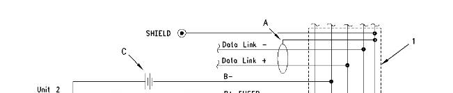
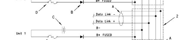
Illustration 1
CCM Wiring Connections for Multiple Generator Sets
g00648895
Shield (A) should be grounded in one location only. The shield should be grounded as near to the negative battery terminal as possible.
5N-4988 Diode (B) is necessary only when multiple gensets are connected.
Connections to the battery (C) should be made at the EMCP II (if equipped). Connections to the battery can be made at the 24 pin customer connector. The 24 pin customer connector is located on the bottom of the Electronic Instrument Panel (EIP).
The 8D-8724 Fuse (2 amp) (D) should be placed in a fuse block.
You will have electrical noise if the +B and -B lines are in the 4 wire shielded cable with the Cat data link cables. Use twisted pair wiring for the CDL+ and CDL- instead.
(1) Junction box for Unit 2
(2) Junction box for Unit 1
(3) CCM
When multiple units are connected to the CCM, junction boxes must be installed. The junction boxes will allow any engine to be disconnected for service or maintenance without power interruption to the CCM and the other engines.
Copyright 1993 - 2025 Caterpillar Inc. All Rights Reserved. Private Network For SIS Licensees.
Sat Feb 15 00:57:27 UTC+0530 2025
Product: MARINE ENGINE
Model: 3516B MARINE ENGINE 4BW
Configuration: 3516B Marine Long Stroke Engine 4BW00001-UP
Operation and Maintenance Manual
Customer Communication Module (CCM) for Diesel Engines
Media Number -SEBU6874-04
Date -01/03/2000 Date Updated -30/01/2002
Initialization for Direct Connection
SMCS - 1926
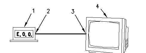
Illustration 1 g00669441
CCM to Host Equipment Direct Connection
(1) CCM
(2) CCM RS-232C port
(3) Computer RS-232C port
(4) Host equipment
Make sure that the following equipment is available:
i01226763
• A personal computer. Refer to "Caterpillar CCM PC For Windows: Getting Started Manual" for specifications on the PC.
• The proper RS-232C cables are required for the particular installation. Refer to the Operation and Maintenance Manual, "RS-232C Cable Requirements".
• The CCM PC Software for Windows. This software is available from Caterpillar.
Procedure
Perform the following procedure to initialize communication with the host equipment that is connected directly to the CCM.
Note: The host equipment and the CCM should be turned OFF before you change the cables to the serial ports.
1. The CCM should be installed with all of the wiring. Refer to Operations and Maintenance Manual, "General Wiring Diagram" and "RS-232C Cable Requirements".
2. Determine the parameters for communication for the installation. The default rate of communication (bits per second or bps) is 9600. The remaining default settings from the factory are no parity, 8 data bits, and 1 stop bit. These parameters will work well in most installations. Use the Operations and Maintenance Manual, "Communication ParametersIdentify" to determine the parameters of communication that are stored in the CCM.
3. Load the CCM PC For Windows software into the PC. Refer to the "Caterpillar CCM PC For Windows: Getting Started Manual". Start the CCM PC program and connect to the CCM.
4. Go to the Data Link pull-down menu. Select ECM, CCM. Go to the CCM configuration screen in the Utilities menu. Set the parameters for communication to match the values that were chosen in step 2.
5. Use the CCM configuration screen to set the Connection Type to Direct Connection. The CCM is now set at the determined communication configuration.
Note: If the PC is required to communicate with the CCM, go to the Phone Book pull-down menu and select Add or Edit. Set the communication parameters of the PC to the values that were chosen in Step 2.
Note: The electronic controller of each engine must be programmed with the correct engine number for identification on the CCM. The electronic controller is programmed to Engine Number 1 at the factory. Refer to Operation and Maintenance Manual, SEBU6874, "Engine NumberProgram".
Note: After the CCM has been connected to the PC, refer to the "CCM PC Software Users Manual". This manual contains instructions on monitoring and on controlling the engine remotely.
Note: Two conditions must be met before the electronic engine controller will allow control by the CCM. The Engine Control Switch must be in the AUTO position, and the remote initiate contacts must be open. The engine may be monitored with the ECS in any position.
Note: For an EMCP II application, the CCM cannot control the generator set if the GSC is in Service Mode. The generator set can only be monitored.
Product: MARINE ENGINE
Model: 3516B MARINE ENGINE 4BW
Configuration: 3516B Marine Long Stroke Engine 4BW00001-UP
Operation and Maintenance Manual
Customer Communication Module (CCM) for Diesel Engines
Media Number -SEBU6874-04
-01/03/2000
Updated -30/01/2002
Initialization for Remote Connection with Modem
SMCS - 1926
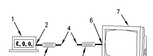
Illustration 1 g00669454
CCM/Host equipment Remote Connection with Modems
(1) CCM
(2) CCM RS-232C port
(3) Answering modem
(4) Telephone line
(5) Originating modem
(6) Computer's RS-232C port
i01226832
You should follow the instructions in Operations and Maintenance Manual, "Initialization for Direct Connection" before you connect by a modem. The user can verify proper operation of the CCM at the location. The user can also become familiar with the CCM.
Make sure that the following equipment is available:
• A personal computer with a terminal emulator software program. Examples of terminal emulators include Procomm, PC-VT, or Terminal under the Accessories window in Microsoft Windows. Refer to "Caterpillar CCM PC For Windows: Getting Started Manual" for specifications on the PC. The user is responsible for understanding the operation of the PC.
• The proper RS-232C cables are required for the particular installation. An RS-232C cable must be temporarily connected from the PC to the Answering Modem. Refer to Operation and Maintenance Manual, "RS-232C Cable Requirements".
• The two modems must support the Hayes AT command set. This is necessary for both the Answering Modem and the Originating Modem.
• The CCM PC For Windows software is required. This software is available from Caterpillar.
Note: Some personal computers will have an internal modem. The internal modem may be used as the Originating Modem. The internal modem must be compatible with the Answering Modem. Consult the instructions for the two modems.
Procedure
Perform the following procedure in order to initialize communication with the CCM and the Answering Modem. The Originating Modem is set up later by the PC software.
Note: In the following steps, the PC and the modems should be turned OFF before you change the cables on the serial ports. When power is reapplied, the modem must be powered up first.
1. The CCM should be installed with all of the wiring. Refer to the Operations and Maintenance Manual, "General Wiring Diagram" and "RS-232C Cable Requirements".
2. Determine the parameters for communication for the installation. The RS-232C default rate of communication (bits per second or bps) is 9600. The remaining default settings from the factory are no parity, 8 data bits, and 1 stop bit. These parameters will work well in most installations. Use the Operation and Maintenance Manual, "Communication ParametersIdentify" to determine the parameters of communication that are stored in the CCM.
Note: The RS-232C serial port communication baud rate is often referred to as the DTE speed. The phone port communication rate is often referred to as the DCE speed.
3. Connect the RS-232C port of the Answering Modem directly to the RS-232C port of the PC. This connection is temporary. This connection is required to set up the Answering Modem.
4. Use the terminal emulator on the PC to set the parameters for communication for the RS232C port. Use the same values that were chosen in step 2.
5. Several commands must be sent to the Answering Modem that set the parameters for communication to the proper values. The examples in Table 1 are Hayes AT commands. Actual command sets vary widely between modem manufacturers. Consult the manual for the modem. Save these parameters to the modem memory.
Table 1
Typical Answering Modem Setup Commands
a
Set the modem to the factory defaults. This is important if the setup of the modem is unknown. AT&F
Set to communicate in error control and in asynchronous mode.
b
c
NOTE: If the modem does not support this command, enter the AT command for error control. Set to communicate in asynchronous mode with a separate command (Item c). Otherwise go to Step d.
Set to communicate in asynchronous mode. Note: If the &Q5 command is supported, the modem is already in asynchronous mode, and this command should not be sent.
AT&Q5
AT&Q0
d
e
Set Auto answer to ON. This tells the modem to answer the phone line after the first ring. If left at 0, the modem will never answer an incoming call. The value of this register can be seen with the ATS0? command.
Set Flow Control to XON/XOFF. This turns off RTS/CTS hardware handshaking between the modem and CCM since the CCM does not have RTS or CTS lines. It turns on the XON/XOFF software handshaking.
f Set DCD to track status of carrier detect signal. This causes the DCD line from the modem to follow the state of the phone line carrier. When the call to the CCM's modem has been made and the modem to modem handshaking is done, the DCD line will change and allow the CCM to receive data.
Note: This is very important. If the DCD line is not at the right state, the CCM cannot receive data.
g Set DTR to monitor DTR signal and hang up and reset modem on an on-to-off DTR transition. This
ATS0=1
AT&K4
AT&C1
AT&D3
causes the modem to hang up and reset if the CCM drops the DTR line.
h Result codes do not have to be returned. Or, if the result codes are returned, the codes must be in originate mode, but not in answer mode.
i Set DTR transition response delay to maximum value less than 10 seconds. This example would cause the modem to hang up the line 2.5 seconds after the DTR line from the CCM changes. Note: Refer to your particular manual. Some modems specify the time in 1/100th of a second, and some in 1/10th of a second.
j Set delay before forced hang-up to maximum value less than 3 seconds.
k Write the setup parameters into memory 0. When the setup parameters are written, any that were not changed are stored into the memory.
l Set to recall memory 0 on reset.
m
View the modem active profile. This is an optional command that allows the user to view the above parameters stored in the modem. The profile should be written down and saved for future reference.
ATQ2
ATS25=250
ATS38=2
AT&W0
AT&Y0
AT&V
6. The setup for the Answering Modem is now complete. Disconnect the PC from the Answering Modem. Connect the PC directly to the CCM. Refer to the Operation and Maintenance Manual, "RS-232C Cable Requirements".
7. Load the CCM PC for Windows software into the PC. Refer to"Caterpillar CCM PC For Windows: Getting Started Manual". Start the CCM PC software and connect to the CCM.
8. Go to the Data Link pull-down menu. Go to the Utilities menu and select CCM configuration. Set the communication parameters to match the values that were chosen in Step 2.
9. Go to the Phone Book pull-down menu and select Add or Edit. Set the communication parameters of the PC to match the values that were chosen in Step 2.
10. The electronic engine controller of each engine must be programmed with the correct engine number to identify each ECM to the CCM. The electronic engine controller is programmed to Engine Number 1 at the factory. Refer to Operation and Maintenance Manual, "Engine Number - Program".
11. Remove power from the CCM by removing the wire that is connected to the +B terminal. Turn off the power to the Modem. Disconnect the PC from the CCM.
12. Connect the PC, the modems, and the CCM as desired for the final site installation. Refer to Operation and Maintenance Manual, "RS-232C Cable Requirements".