DOWNLOAD LINK
For some reason if link does not work download this pdf and then click
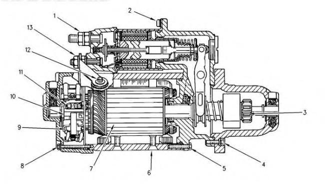
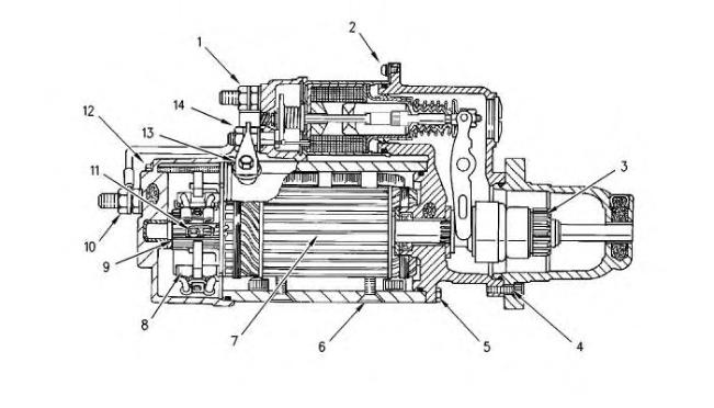
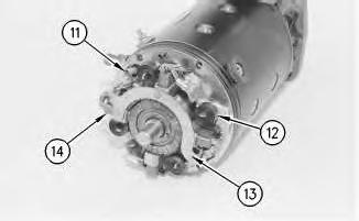
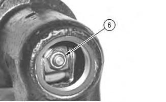
(6) Field Winding Screws
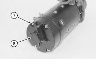
(7) Laminated Core
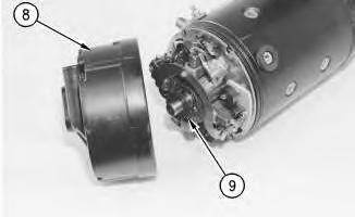
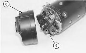
(8) Brush
(9) Commutator
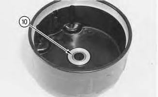
(10) Ground Terminal Nut
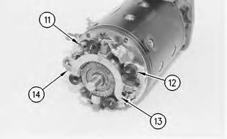
(11) Brush Lead Screws
(12) Rear Housing Bolt
(13) Motor Terminal Bolt
(14) Motor Terminal Nut Copyright 1993 - 2024 Caterpillar Inc. All Rights Reserved. Private Network For SIS Licensees. Thu Oct 17 09:46:55 UTC+0530 2024
Product: GENERATOR SET
Model: 3516 GENERATOR SET 8TW
Configuration: 3516 Generator Set 8TW00001-UP
Disassembly and Assembly
37-MT, 41-MT, and 42-MT Series Starting Motors Media
Starting Motor - Assemble - 37-MT and 41-MT
SMCS - 1453-016
Assemble the Starting Motor Table 1
Required Tools
Illustration 1
1. Put SAE 20W oil on all bushings, seals and oil wicks.
i01559761
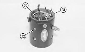
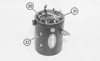
2. Put field winding coil (29) and pole shoes (30) in position in the starting motor housing. Put 9s-3263 Thread Lock Compound on the threads of screws (31). Tighten to a torque of 20.3 ± 2.3 N·m (179.7 ± 20.4 lb in).
Illustration 2
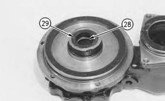
3. Install bushing (27) and seal (28) into the shift lever housing. Use tool group (B) .
Illustration 3
4. Put the O-ring on the shift lever housing (22) .
5. Install the seals on pin (26). Hold shift lever (24) in shift lever housing (22) and install pin (19) through the housing and lever (24). Install ring (23) with tool (A) .
g00810276
g00810419
4
6. Put shift lever housing (22) in position on the starting motor housing. Install bolts (25) and tighten bolts (25) to a torque of 18.9 ± 2.6 N·m (167.3 ± 23.0 lb in).
Illustration 5
g00810429
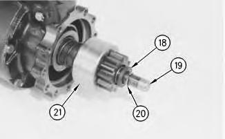
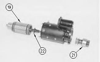
7. Put 5P-0960 Molybdenum Grease on the armature bushing areas. Do not put grease on the armature core or the commutator. Install washer (21) on armature (18). Put armature (18) into the starting motor housing. Hold pinion drive (20) in the shift lever fork and insert armature (18) through the shift housing and pinion drive.
Note: The pinion drive that is on the 41-MT starting motor is not same pinion drive that is shown. The pinion drive is similar to a 42-MT starting motor. Refer to Disassembly and Assembly, "Starting Motor - Assemble".
Illustration
g00810272
6
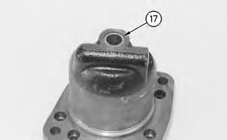
8. Put retainer (17) on armature shaft (18). Install ring (19) into the groove and force retainer (17) over ring (19) in order to lock the ring in position.
Illustration 7
9. Install bushing (16) into the pinion drive housing with tool group (B) .
Illustration 8
Illustration
g00810266
g00810257
g00810444
9
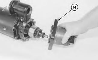
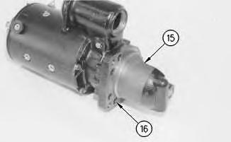
10. Put pinion drive housing (14) in position on shift lever housing (22). Install bolts (15) and tighten the bolts to a torque of 23.7 ± 6.1 N·m (209.8 ± 54.0 lb in).
Illustration 10
Illustration 11
Illustration
g00810249
g00810455
g00810245
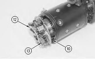
11. Install brushes (11) on brush holder (12). Tighten the screws to a torque of 2.9 ± 1.0 N·m (25.7 ± 8.9 lb in).
12. Put the brush holder in position on the starting motor housing. Connect three leads (10). Tighten the screws to a torque of 2.9 ± 1.0 N·m (25.7 ± 8.9 lb in). Push the brushes against the commutator so the brush springs are on top of the brushes.
Illustration 12
13. Install bushing (10) into rear of the housing with tool group (B) .
13
g00810242
Illustration
g00810478
14
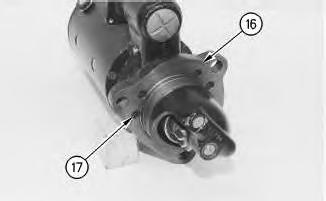
14. Install the O-ring seal on the back of the starting motor housing. Put washer (9) on the back of the armature. Put rear housing (6) in position on the starting motor housing. Install bolts (7) and tighten the bolts to a torque of 5.7 ± 1.1 N·m (50.4 ± 9.7 lb in).
15
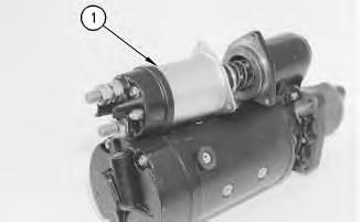
15. Put the O-ring seal on the shift lever housing. Put solenoid (1) in position on the shift housing. Make sure that the end of the plunger is inserted into the shift lever.
Illustration
g00810222
Illustration
g00810493
Illustration 16
16. Install the three bolts and tighten the bolts to a torque of 14.1 N·m (124.8 lb in) to 21.5 N·m (190.3 lb in).
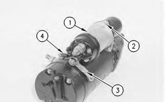
17. Connect motor terminal "MTR" (3) to the starter motor housing. Hold the terminal with a T40 TORX wrench. Tighten the nut on the solenoid motor terminal to a torque of 14.7 ± 3.4 N·m (130.1 ± 30.1 lb in). Tighten the motor terminal bolt to 9.6 ± 1.1 N·m (85.0 ± 9.7 lb in).
18. Connect the shunt wire assembly (4) to the solenoid (1) and to the starting motor. Tighten the nuts for the shunt wire assembly to a torque of 2.6 ± 0.8 N·m (23.0 ± 7.1 lb in).
Illustration 17
g00810580
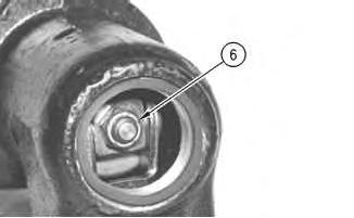
19. Install the nut (6) for the plunger finger tight. The plunger must be adjusted for the correct pinion clearance.
20. Check pinion clearance. Refer to Testing and Adjusting, "Pinion Clearance Adjustment" for the proper adjustment procedure.
Illustration 18
g00820183
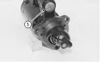
21. Install plug (5) and seal to the shift lever housing.
End By: Install the starting motor. Copyright 1993 - 2024 Caterpillar Inc.
Network For SIS Licensees. Thu Oct 17 09:48:00 UTC+0530 2024
Product: GENERATOR SET
Model: 3516 GENERATOR SET 8TW
Configuration: 3516 Generator Set 8TW00001-UP
Disassembly and Assembly
37-MT, 41-MT, and 42-MT Series Starting Motors Media
-SENR3581-04
Starting Motor - Assemble - 42-MT
SMCS - 1453-016
Assemble the Starting Motor Table 1
Required Tools
Illustration 1
1. Put SAE 20W oil on all bushings, seals and oil wicks.
i01560148
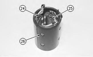
2. Put field winding coil (24) and pole shoes (25) in position in the starting motor housing. Put 9s-3263 Thread Lock Compound on the threads of screws (26). Tighten screws (26) to a torque of 20.3 ± 2.3 N·m (179.7 ± 20.4 lb in).
Illustration 2
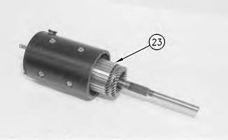
3. Put 5P-0960 Molybdenum Grease on the armature bushing areas. Do not put grease on the armature core or the commutator. Put armature (23) into the starting motor housing.
Illustration 3
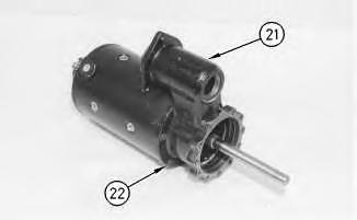
4. Install the outside O-ring seals if it is necessary. Install the shift lever housing (21). Install five bolts (22). Install the brake disc on the armature shaft.
g00810588
g00810585
4
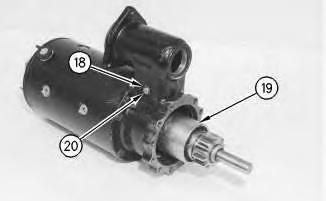
5. Install the pinion drive (19) and the shift lever. Install the O-ring seal if it is necessary. Install the shift lever pin (20). Install the retainer (18) with tool (A) .
Illustration 5
6. Align the pinion drive housing (16). Install six bolts (17) .
Illustration 6
Illustration
g00810582
g00810579
g00818538
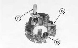
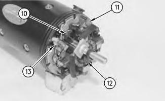
7. Install brushes (15) and negative "-"terminal (14) in the brush holders. Install brush spring (10) against the side of each brush.
7
8. Install the brush holder. Connect the field winding leads (13) to the brush holder (11) .
9. Put the washer (12) onto the armature assembly. Push the brushes (10) into the holders so that the springs are on top of the brushes.
8
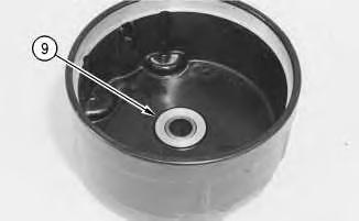
10. Install the bushing (9) into the rear housing if it is necessary.
Illustration
g00810576
Illustration
g00818558
Illustration 9
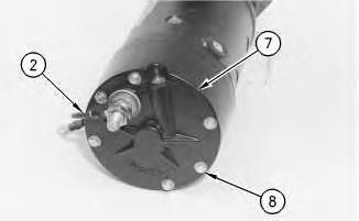
11. Install six bolts (8) and rear housing (7). Torque bolts (8) to 5.7 ± 1.1 N·m (50.4 ± 9.7 lb in). Install wire assembly (2), washers, and negative terminal nuts "-".
Illustration 10
g00810559
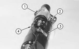
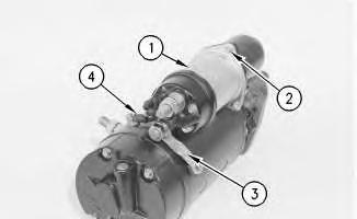
12. Install solenoid (1). Align the solenoid link with the hole in the shift lever. Install three bolts (2) in the shift lever housing. Torque bolts (2) to 17.8 ± 3.7 N·m (157.5 ± 32.7 lb in).
13. Install wire assembly (4). Connect motor terminal "MTR" (3) to the starter motor housing.
g00810574
Illustration 11 g00810580
14. Install pinion clearance adjustment nut (6) .
15. Adjust pinion clearance. Refer to Testing and Adjusting, "Pinion Clearance - Adjust" for pinion clearance adjustments.
Illustration 12 g00818016
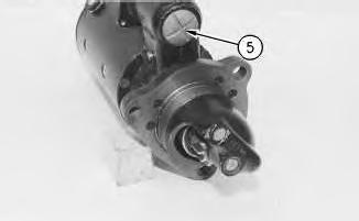
16. Install the O-ring seal and bushing (5) .
Copyright 1993 - 2024 Caterpillar Inc. All Rights Reserved. Private Network For SIS Licensees. Thu Oct 17 09:47:43 UTC+0530 2024
Product: GENERATOR SET
Model: 3516 GENERATOR SET 8TW
Configuration: 3516 Generator Set 8TW00001-UP
Disassembly and Assembly
37-MT, 41-MT, and 42-MT Series Starting Motors
Starting Motor - Disassemble - 37-MT and 41-MT
SMCS - 1453-015
Disassemble the Starting Motor
Start By:
A. Remove the starting motor from the machine.
Note: The disassembly of the 12 volt starting motor is similar to the disassembly of the 24 volt starting motor.
Table 1
Required Tools
A 1P-1855 Retaining Ring Pliers 1
i01365545
1. Disconnect and remove shunt wire assembly (4) and motor terminal connector "MTR" (3) from the solenoid (1) and starting motor.
2
Illustration 3
2. Remove the plug (5) and seal from the shift lever housing. Remove the nut (6) that is inside the shift lever housing. The nut holds the plunger to the shift lever.
3. Remove bolts (2) and solenoid (1) from the shift lever housing. Do not disassemble the solenoid. The parts inside the solenoid are not serviceable.
Illustration
g00820183
g00810580
4
5
4. Mark the following components for correct assembly: rear housing (8), pinion drive, shift lever housing and starting motor housing. Remove four bolts (7) and rear housing (8). Remove washer (9) from the armature. Remove the O-ring seal from the starting motor housing, if necessary.
6
Illustration
g00810222
Illustration
g00810478
Illustration
g00810242
5. Remove bushing (10) from the rear housing, if necessary.
7
6. Lift each brush spring (12) and put the spring on the left side of the brush (14). Disconnect three leads (11) and remove brush holder (13) .
7. Remove brushes (14) from the brush holder.
Illustration 8
8. Remove six bolts (16) and pinion drive housing (15) .
Illustration
g00810245
g00810249
Illustration 9
9. Remove bushing (17) from the pinion drive housing, if necessary.
Illustration 10
g00810266
Illustration 11
g00810429
g00810257
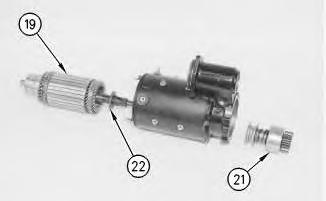
10. Drive retainer (18) backward away from ring (20) that is below the retainer. Remove the ring and the retainer. Remove armature (19) from pinion drive (21) and the starting motor and the shift lever housing (23). Remove the washer (22) from the armature (19) .
Note: The pinion drive that is on the 41-MT starting motor is not the same pinion drive that is shown. The pinion drive is similar to a 42-MT starting motor. Refer to Disassembly and Assembly, "Starting Motor - Disassemble".
11. Remove pinion drive (21) from the shift lever forks (25) .
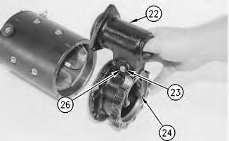
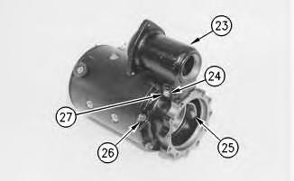
12. Remove five bolts (26) and shift lever housing (23). Remove ring (24) with tool (A), pin (27) and shift lever (25). Remove the seals from the pin, if necessary.
13. Remove the O-ring seal from the shift lever housing, if necessary.
13
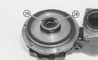
14. Remove seal (28) and bushing (29) from the shift lever housing, if necessary.
Illustration 12
g00810272
Illustration
g00810276
15. Remove eight screws (32), field winding coil (30), and pole shoes (31) from the starting motor housing. It may be necessary to use an impact driver to remove screws (32). One of the screws is the negative terminal.
16. Clean the armature, field winding coil, and pinion drive with mineral spirits and a brush.
Note: If the commutator is dirty, the commutator may be cleaned with Number 00 sandpaper. Do not use emery cloth.
17. Inspect all parts for wear and damage.
Thu Oct 17 09:47:28 UTC+0530 2024
Product: GENERATOR SET
Model: 3516 GENERATOR SET 8TW
Configuration: 3516 Generator Set 8TW00001-UP
Disassembly and Assembly
37-MT, 41-MT, and 42-MT Series Starting Motors
Starting Motor - Disassemble - 42-MT
SMCS - 1453-015
Disassemble the Starting Motor
Note: The disassembly and assembly that follows is of the 24 volt starting motor. The 12 volt is similar.
Table 1
Required Tools
i01559954