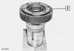
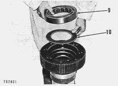
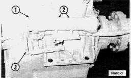
CAT Caterpillar 3512 Service Repair Manual PDF Download
Note: Use Bookmarks panel to navigate
Product: MARINE ENGINE
Model: 3512 MARINE ENGINE 66Z
Configuration: 3512 Marine Engine 66Z00579-UP
Disassembly and Assembly
7251 MARINE GEAR
Media Number -REG00917-00 Publication Date -01/03/1979 Date Updated -10/10/2001
Planetary Reduction Gears
SMCS - 4453-11; 4453-12
The planetary reduction gears are mounted on the rear of the marine gear housing. The planetary reduction is the only reduction that takes place in the marine gear.
Removal
1. Remove the oil manifolds, oil filter, magnetic strainer, control valve and oil pump. See covering topics.
NOTE: The planetary reduction gear removal and installation can be facilitated by the removal of the upper shaft group. With the upper shaft group in place, there is interference between the lifting eye and the pump drive shaft.
2. Remove two diagonally opposed bolts and install two 5/8"-11 (NC) guide pins.
3. Attach a suitable hoist and support the reduction gear.
4. Install two 1/2"-13 (NC) forcing screws in the holes provided.
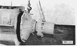
5. Remove the remaining bolts securing the reduction gear to the lower housing and separate the reduction gear from the lower housing.
REMOVING PLANETARY REDUCTION GEAR
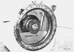
6. Remove the bolts securing the ring gear to the housing and, using two forcing screws, remove the ring gear.
REMOVING THE PLANETARY RING GEAR
Planetary Reduction Gear Installation
Before installing the reduction gear, inspect all gaskets and replace if damaged.
The guide pins, installed for removal, should be used to pilot the reduction gear when it is being installed.
Planetary Reduction Gear Disassembly
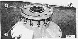
PREPARING TO DISASSEMBLE PLANETARY REDUCTION GEAR 1-Retainer. 2-Bolts (six). 3-Coupling.
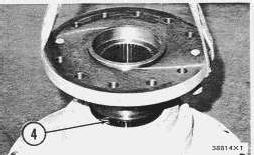
2. Lift the coupling (3) from the carrier shaft (4).
REMOVING COUPLING 4-Carrier shaft.
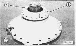
3. Remove the bolts securing the seal retainer (6) to the cover (7).
DOWNLOAD LINK
For some reason if link does not work download this pdf and then click
4. Install two 3/8"-16 (NC) forcing screws in the bearing retainer (6) and separate it from the cover (7).
REMOVING SEAL RETAINER
5-Seals. 6-Bearing retainer. 7-Cover.
5. Inspect the seals (5) and O-ring seal for damage or wear and replace as necessary.
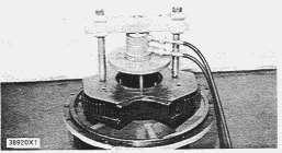
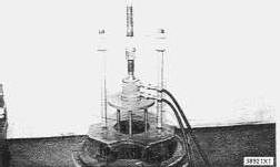
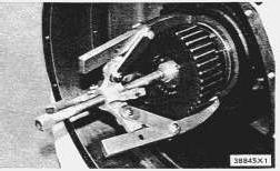
6. Using a 1H3107 Push Puller, 1H3108 Rods, FT866 Plate and a suitable Hydraulic Pump Group, push the carrier shaft bearing off the shaft and out of the cover.
REMOVING BEARINGS FROM CARRIER SHAFT
NOTE: When the bearings are being removed, it is necessary to change the FT867 Rods as the bearings are pushed off the shaft. As each set of legs reaches its limit of travel, the next longer set of legs must be used. When the FT867 Rods are changed, it is necessary to use 1H3109 Legs, 5F7366 Screw. 5F7353 Washer, 3H466 Nut and an 8B7561 Step Plate with the 1H3108 Push Puller and 7F9540 Hydraulic Puller to push the bearing off the shaft.
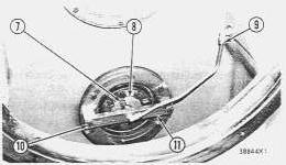
7. Using a steel bar or rod and a suitable hoist, lift the planet carrier out of the cover.
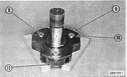
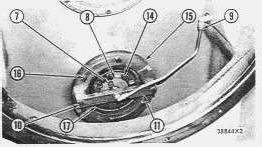
8. Block the planet carrier (9) so the planet gear shaft (8) can be removed.
9. Remove the bolts (10) and locks securing the planet gear shafts (8) and remove the shaft.
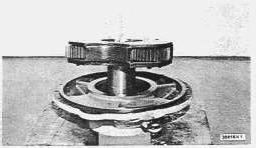
REMOVING BEARINGS FROM CARRIER SHAFT
REMOVING PLANET CARRIER
NOTICE
To prevent damage to the planet gear shaft, do not let it fall from the carrier.
10. Remove the planet gears and washers from the carrier.
11. Inspect all parts for damage and wear.
Planetary Reduction Gear Assembly
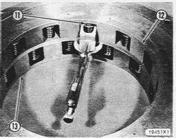
1. Install washers, planet gears (11) and planet gear shafts (8) into planet carrier (9). Secure all parts with the locks and bolts (10).
2. Position the carrier shaft (4) in a vertical position.
3. Lower the reduction gear housing over the carrier shaft before installing the roller bearing races.
NOTE: Heat the taper roller bearings in oil, not to exceed 275° F (135° C), to facilitate installation.
4. Install the first tapered roller bearing on the shaft with the small end of the taper upward.
5. Install the outward forward bearing race, small end downward. The outer bearing races are a slip fit in the housing.
6. Install the spacer for the outer races into the housing.
7. Install the spacer for the inner races on the carrier shaft. Lubricate the seal rings and the sealing surface to facilitate installation.
8. Install the remaining bearing outer race, tapered roller bearing, bearing retainer (6) and coupling (3) to complete the installation.
9. Be sure the lips of seals (5) are installed with the inner seal lip toward the inside; the outer seal lip toward the outside. Copyright 1993 - 2024 Caterpillar Inc.
Nov 15 23:09:45 UTC+0530 2024
Rights Reserved.
Network For SIS Licensees.
Product: MARINE ENGINE
Model: 3512 MARINE ENGINE 66Z
Configuration: 3512 Marine Engine 66Z00579-UP
Disassembly and Assembly
7251 MARINE GEAR
Media Number -REG00917-00 Publication Date -01/03/1979 Date Updated -10/10/2001
Lower Shaft
SMCS - 4453-11; 4453-12
Removal
1. Remove the upper shaft group. See the covering topic.
2. Remove the planetary reduction gear. See the covering topic.
PREPARING TO REMOVE LOWER SHAFT
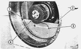
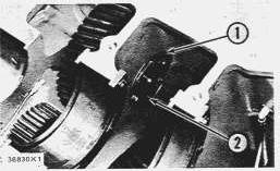
1-Bolts (four). 2-Baffle. 3-Bolts (two). 4-Sun gear and shaft.
3. Remove bolts (1) and bolts (3) and remove baffle (2). There are nuts, spacers and a splash pan behind the baffle secured by bolts (3).
PREPARING TO REMOVE SUN GEAR
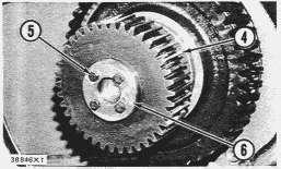
4-Sun gear and shaft. 5-Bolts (four). 6-Plate.
4. Remove bolts (5) and locks and plate (6).
REMOVING SUN GEAR
5. Using an 8H705 or a 1P2332 Puller Assembly and an 8B7561 Step Plate, pull the sun gear off the shaft.
6. If the sun gear does not require being removed separately, the sun gear and shaft can be removed as a unit by disconnecting lubrication line (9), removing bolts (10) and bracket (11). Remove bolts (7) and pull the sun gear and shaft out from the rear.
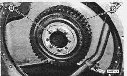
PREPARING TO REMOVE ASTERN DRIVEN GEAR
12-Bolts (eight). 13-Astern driven gear.
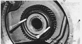
7. Remove bolts (12) and insert forcing screws as shown.
REMOVING ASTERN DRIVEN GEAR
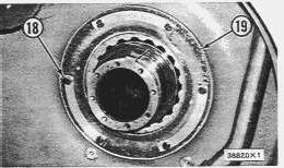
8. Loosen line (9), remove bolts (10) and lift off bracket (11). Remove bolts (14) and retainer (18). Remove bolts (7) and plate (8). Remove bolts (16) and retainer (15). Remove bolts (18) and retainer (19).
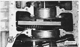
9. Install the FT850 Locking Bracket between the ahead driven gear (20) and the housing web. Tighten the locking bracket, adjusting bolts evenly between the gear and housing web. The adjusting bolts will "bottom out" against the web and provide a larger surface area on the web when the lower shaft is pulled out of the housing. This will prevent breaking the web when a force is exerted on the lower shaft and ahead driven gear.
REMOVING LOWER SHAFT
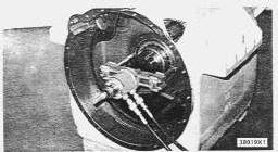
10. Using an 8B7548 Push Puller, 8B7550 Legs, 8B7557 Adapters, 7F1858 Screw, 5F7352 Thrust Bearing, 7F1859 Nut, 1P1842 Bearing Pulling Adapter and a 7F9540 Hydraulic Puller, start to pull the shaft from the housing.
NOTICE
Be sure the key holding the ahead driven gear to the shaft is free while removing the shaft to prevent damage to the housing.
11. After pulling the shaft to the bridge, change to 5F7369 Legs, install a sling through the ahead driven gear and continue pulling the shaft as shown.
12. Inspect the bearings and replace if worn or damaged.
Lower Shaft Installation
1. Install the lower shaft through the first web of the housing and through ahead driven gear (20). Push the shaft in as far as possible by hand. Make sure keyway and key on lower shaft and gear (20) are aligned.
2. Install retainer (15), locks and bolts (16).
3. Install bearing retainer (17) and using bolts (14), pull the lower shaft into place.
4. Install bearing retainer (19) and bolts (20).
5. Install the key in the lower shaft.
NOTE: Gears can be assembled on the shafts by heating them in oil to 275° F (135° C) Max., and quickly slipping them on the shafts.
6. Install gear (13) on the lower shaft.
7. Install gear retainer and bolts (12).
8. Remove bolts (8) and retainer (17).
9. Install the sun gear shaft and secure at the front end with retainer (8), locks and bolts (7).
10. Replace retainer (17) and bolts (14).
11. Install sun gear (4) and secure with plate (6), locks and bolts (5).
12. Install the brass lubrication tube and bracket (11), locks and bolts (10). Bracket (11) will not bottom against retainer (15) if the brass lubrication tube is installed incorrectly.
13. Connect lubrication line (9) at housing wall.
14. Install baffle (2), locks and bolts (1), nuts, spacers and splash pan behind baffle (2) secured with bolts (3).
Copyright 1993 - 2024 Caterpillar Inc. All Rights Reserved. Private Network For SIS Licensees.
Fri Nov 15 23:09:30 UTC+0530 2024
Product: MARINE ENGINE
Model: 3512 MARINE ENGINE 66Z
Configuration: 3512 Marine Engine 66Z00579-UP
Disassembly and Assembly
7251 MARINE GEAR
Media Number -REG00917-00
Idler Shaft
SMCS - 4453-11; 4453-12
Removal
Publication Date -01/03/1979
Date Updated -10/10/2001
1. Remove the upper housing, upper shaft group, planetary reduction gear and ring gear. See the covering topics.
PREPARING TO REMOVE IDLER GEAR AND IDLER GEAR SHAFT
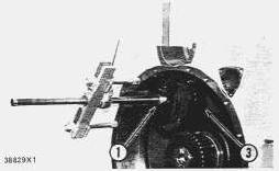
1-Idler gear shaft. 2-Bolts (six).
2. Remove the bolts (2) and locks from the front end of the idler gear shaft (1).
3. Attach a sling and hoist to the idler gear (3) to prevent the gear from falling when the shaft (1) is pushed out.
REMOVING IDLER GEAR AND SHAFT
1-Idler gear shaft. 3-Idler gear.
4. Using an 8B7548 Push Puller, 8B7550 Legs, two 8B7556 Adapters, 8B7561 Step Plate, 8S6586 Screw and an 8H684 Ratchet, push the idler gear shaft from the idler gear and housing as shown.
NOTICE
The idler shaft will fall into the lower housing, after it is pressed out, unless it is supported.
When removing the idler gear, hold the bearings in place to prevent them from being damaged on the housing.
Idler Shaft Installation
1. Inspect the tapered roller bearings in the idler gear and replace if worn or damaged.
2. Lower the idler gear into position with the bearings lined up correctly.
3. Line up the six holes in the shaft with the holes in the housing before the shaft is pulled in.
4. Using an 8B7548 Block, placed diagonally across and centered over the idler shaft hole, and an 8B7750 Leg, threaded into the tapped hole in the idler gear shaft, add spacers on the 8B7550 Leg. Tighten the nut and pull the shaft through the idler gear and into the rear web of the housing.
Fri Nov 15 23:09:19 UTC+0530 2024
Product: MARINE ENGINE
Model: 3512 MARINE ENGINE 66Z
Configuration: 3512 Marine Engine 66Z00579-UP
Disassembly and Assembly
7251 MARINE GEAR
Media Number -REG00917-00
Ahead And Astern Clutches And Clutch Shafts
SMCS - 4453-11; 4453-12
Updated -10/10/2001
The clutches and clutch shafts can be removed from the marine gear as a unit for servicing. This can be accomplished without removing the marine gear from the diesel engine. The upper housing, oil pump, oil filter, oil manifolds, control valve and oil cooler must be removed in order for the clutches and clutch shafts to be removed.
Upper Housing Removal
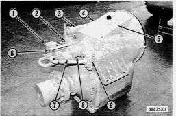
1. Remove oil pump (7), oil filter (1), control valve (2), oil manifold (6), oil manifold (8), oil cooler (3) and magnetic strainer (9). See the covering topics.
2. Remove bolts (4) and lift cover (5) from the top housing. Inspect the gasket and replace if necessary.
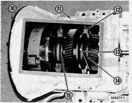
3. Remove the bolts (11) securing the upper housing to the lower housing.
4. Disconnect oil line (13) at position indicated.
5. Bend locks and loosen bolts (14) and also the locks and bolts securing the rear retainers (15).
NOTE: Before saddle bolts (12) are loosened, place two four inch wooden blocks under the clutch end of the shaft between the drive ring and the lower housing. The clutch end of the shaft is overbalanced and will drop into the lower housing unless it is supported.
6. Loosen and remove saddle bolts (12).
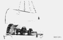
7. With the aid of four forcing screws, separate the upper housing from the lower housing and lift the upper housing off as shown.
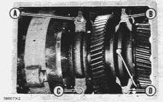
7. Install and initially tighten saddle bolts (12) in a C-B-D-A sequence to 150 lb. ft. (20,7 mkg). Tighten the bolts in the same sequence to 265 ± 35 lb. ft. (36,6 ± 4,8 mkg).
TIGHTENING UPPER HOUSING SADDLE BOLTS
8. Connect line (13) to fitting on saddle.
9. Install the gasket and top cover (5) using bolts (4).
Upper Shaft
Removal
1. Remove the upper housing. See the covering topic.
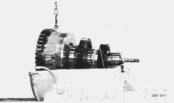
2. Install a 1/2" forged lifting eye and attach a hoist to the shaft group.
3. Remove bolts (4) and (5) securing rear retainers (3) and (6).
REMOVING UPPER SHAFT
4. Attach one end of a nylon sling to the hoist and hook the other end over the end of the small shaft. Adjust the sling so a minimum of weight is transferred to the small shaft.
Upper Shaft Installation
UPPER SHAFT INSTALLATION
7-FT836 Bearing Cap.
NOTE: Before installing the shaft group in the lower housing, be sure the front retainers (1) and (2) are tight and rear retainers (3) and (6) are loose. This will allow the shaft to be lowered into its correct position.
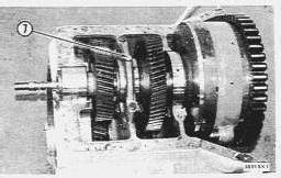
Place the upper shaft in the lower housing and, with the shaft supported by the hoist, place FT836 Bearing Cap (7) over the bearings as illustrated. This will insure that all of the top shaft bearings are properly seated.
Install the upper housing. See the covering topic.
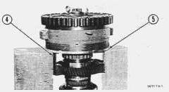
1. Place the upper shaft group in a vertical position by blocking up under the plate assembly as illustrated.
2. Remove all but two of the bearing retainer nuts (1) leaving the remaining two accessible to a wrench.
FT840 RETAINING BRACKET
4-FT840 Retaining Brackets. 5-Plate assembly.
NOTE: Before removing stud nuts (2) and the remaining two nuts (1), install two FT840 Brackets as illustrated to prevent shaft from sliding out of the clutch pack.
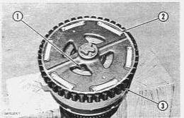
3. Remove the stud nuts (2), retainer nuts (1) and remove the clutch spider (3), being careful not to damage the clutch studs.
REMOVING CLUTCH SPIDER
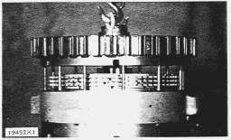
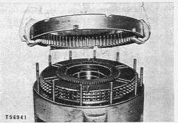
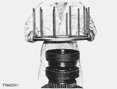
REMOVING ASTERN CLUTCH DRIVE RING
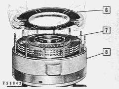
NOTE: If the old plates are to be reused, mark the clutch plates in a manner so they will be assembled in the same order. This will accommodate any wear pattern.
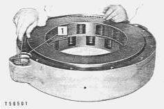
5. Inspect the ahead and astern clutch plates and replace if worn or damaged. The clutch plates are installed alternately, beginning with a sintered bronze plate.
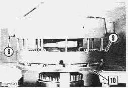
NOTE: The astern piston can also be removed by lifting the cylinder assembly off the piston after the retaining rings (11) have been removed. The cylinder assembly will then have to be turned over in order to remove the retainer rings on the ahead piston.
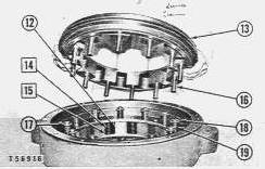
6. After the retainer rings (11) have been removed, turn the cylinder over so that the astern piston (13) is on top.
NOTICE
Use care in turning over cylinder assembly as the astern piston may fall out if not held in place.
7. Lift off astern piston (13) being careful not to damage the pins (16).
8. Remove retainer rings (17), washers (18), springs (19) and lift off cylinder assembly from ahead piston (12).
Clutch Assembly
1. Lift cylinder assembly (8) and set it on the ahead piston (12). Install springs (19), washers (18) and retainer rings (17).
2. Install springs (14) and washers (15) into place and set astern piston (13) into the cylinder.
3. Turn the cylinder assembly (8) over, holding astern piston (13) in place. Install retaining rings (11).
4. Install plate assembly (10) on main shaft and bolt FT840 Bracket in place.
5. Install ahead clutch drive ring (9) on plate assembly (10).
6. Install the clutch plates alternately beginning with a sintered bronze plate.
7. Install cylinder assembly (8) on ahead clutch drive ring (9).
8. Install astern clutch drive ring and clutch plates in the same sequence as for the ahead clutch.
9. Install the clutch spider (3), being careful not to damage the clutch studs, and install stud nuts (2).
10. Install bearing retaining nuts (1).
Dump Valve Removal and Installation
PREPARING TO REMOVE DUMP VALVE BODY
1-Retainer ring.
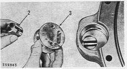
The clutches contain two dump valves.
REMOVING VALVE BODY
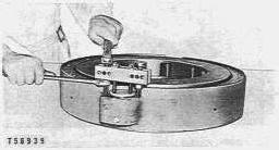
1. Remove the valve body using a 5F7344 Block, two 1D4719 Nuts, two L1329 Bolts, two 8B2377 Bolts, two 4B4280 Washers and two 4B4276 Washers.
REMOVING DUMP PISTON FROM BODY 2-Dump piston. 3-Valve body.
NOTE: When installing, be sure the arrow on the dump valve is pointing outward from the clutch cylinder as illustrated. The solid end of the dump valve piston marked "OUT" must also be positioned as illustrated.
Clutch Drive Spider and Oil Pump Drive Shaft
Disassembly
NOTE: The oil pump drive shaft is splined to the spider and can be removed by lifting it straight up from the spider after the four bolts securing the retainer, cover and coupling are removed.
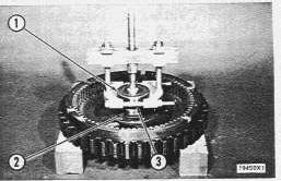
1. Using an 8B7551 Bearing Pulling Attachment, an 8B7548 Push Puller, 8B7550 Legs, an 8B7560 Step Plate and an 9H684 Wrench, pull the top bearing assembly (1) from the clutch spider as illustrated.
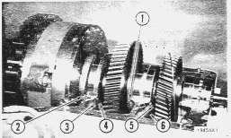
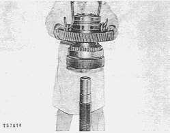
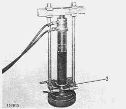
1. Using a 8B7548 Push Puller, 8B7549 Puller Legs, 7F9540 Hydraulic Puller, a 5F9886 Adapter and a suitable Hydraulic Pump Group, pull the rear thrust bearing assembly (1) and the astern driving gear (2) off the astern driving shaft.
REMOVING AHEAD DRIVE SHAFT ASSEMBLY
2. Using a 1H3107 Push Puller, 1H3109 Puller Legs, 1H3110 Bearing Pulling Attachment, 7F9540 Hydraulic Puller and a suitable Hydraulic Pump Group, remove the inner bearing race (3) from the astern drive shaft.
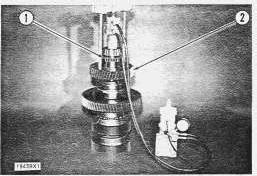
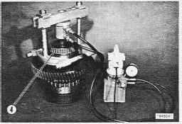
3. Using a 1H3107 Push Puller, 1H3110 Bearing Pulling Attachment, 5F7694 Plug, 7F9540 Hydraulic Puller and a suitable Hydraulic Pump Group, remove the double tapered thrust bearing (4) from the ahead drive shaft.
REMOVING BEARING INNER RACE FROM ASTERN DRIVE SHAFT
3-Inner race.
REMOVING DOUBLE TAPERED THRUST BEARING FROM AHEAD DRIVE SHAFT
4-Double tapered thrust bearings.
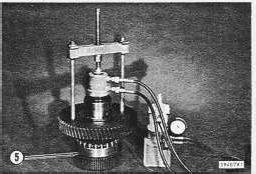
REMOVING AHEAD DRIVING GEAR
5-Outer race of front support bearing.
4. Using a 1H3107 Push Puller, 1H3108 Puller Legs, 7F9540 Hydraulic Puller, 5F7694 Plug and a suitable Hydraulic Pump Group, remove the ahead driving gear from the ahead drive shaft.
5. Remove the outer race (5).
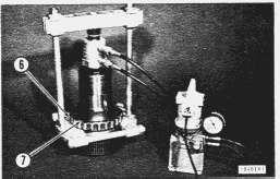
REMOVING FRONT SUPPORT BEARING FROM AHEAD DRIVE SHAFT 6-Front support bearing. 7-Inner race.
PREPARING TO REMOVE INNER BEARING FROM AHEAD DRIVE SHAFT 8-Retainer.
REMOVING INNER BEARING AND SHIELD 9-Bearing. 10-Shield.
6. Using a 1H3107 Push Puller, 1H3108 Puller Legs, 1H3110 Bearing Pulling Attachment, 5F7694 Plug, 7F9540 Hydraulic Puller and a suitable Hydraulic Pump Group, remove bearing (6) and inner race (7).
7. Inspect all bearings and replace if worn or damaged.
Main Shaft Assembly
1. Install shield (10) and bearing (9) into the ahead drive shaft.
2. Install bolts securing retainer (8).
NOTE: Bearings and gears can be assembled on shafts by heating them in oil to 275° F (135° C) Max. then quickly slipping them on the proper shafts (seat the bearings with a soft hammer).
3. Install inner race (6) and bearing (7) on the shaft.
4. Install outer race of front support bearing (5).
5. Install the ahead driving gear on the ahead drive shaft.
6. Install double tapered thrust bearings (4) on the ahead drive shaft.
7. Install bearing inner race (3) on astern drive shaft.
8. Install ahead drive shaft assembly on the astern driving shaft.
9. Install astern driving gear (2) and rear thrust bearing assembly (1) on the astern driving shaft.
Copyright 1993 - 2024 Caterpillar Inc. All Rights Reserved. Private Network For SIS Licensees. Fri Nov 15 23:09:06 UTC+0530 2024
Product: MARINE ENGINE
Model: 3512 MARINE ENGINE 66Z
Configuration: 3512 Marine Engine 66Z00579-UP
Disassembly and Assembly
7251 MARINE GEAR
Media Number -REG00917-00 Publication Date -01/03/1979 Date Updated -10/10/2001
Oil Cooler Removal And Installation
SMCS - 4453-11; 4453-12
OIL COOLER REMOVAL
1-Oil cooler. 2-Mounting bolts (two). 3-Line to lower shaft.
Disconnect line (3) at the swivel joint.
Remove mounting bolts (2) and remove oil cooler (1).
Copyright 1993 - 2024 Caterpillar Inc. All Rights Reserved. Private Network For SIS Licensees. Fri Nov 15 23:08:54 UTC+0530 2024
DOWNLOAD LINK
For some reason if link does not work download this pdf and then click