

Product: EXCAVATOR
Model: 349F L EXCAVATOR BZ2
Configuration: 349F & 349F L Excavators BZ200001-UP (MACHINE) POWERED BY C13 Engine
Disassembly and Assembly
C13 Engine for Caterpillar Built Machines
Media Number -UENR0131-06
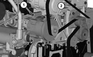
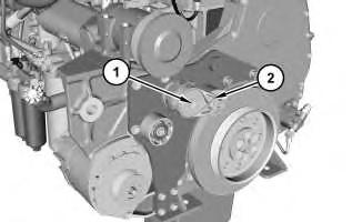
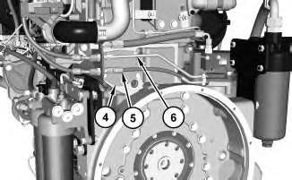
Accessory Drive - Remove and Install - Brackets and Pulleys
SMCS
Removal Procedure
Start By:
Product: EXCAVATOR
Model: 349F L EXCAVATOR BZ2
Configuration: 349F & 349F L Excavators BZ200001-UP (MACHINE) POWERED BY C13 Engine
Disassembly and Assembly
C13 Engine for Caterpillar Built Machines
Media Number -UENR0131-06
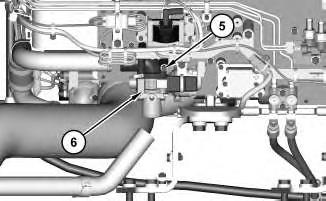
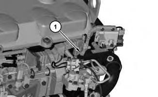
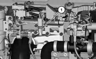
Air Control Valve - Remove and Install
Removal Procedure
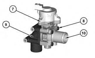
Installation Procedure
Product: EXCAVATOR
Model: 349F L EXCAVATOR BZ2
Configuration: 349F & 349F L Excavators BZ200001-UP (MACHINE) POWERED BY C13 Engine
Disassembly and Assembly
C13 Engine for Caterpillar Built Machines
Media Number -UENR0131-06
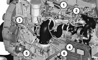
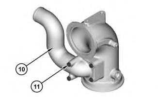
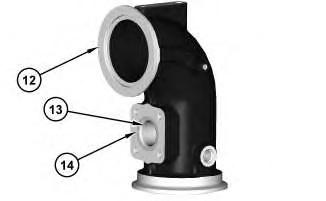
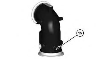
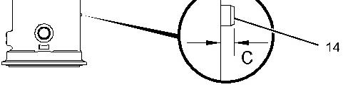
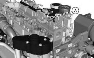
Air Inlet Elbow - Remove and Install
Removal Procedure
Required Tools Tool
Start By:
-27/06/2018
i05351528
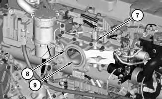
Installation Procedure

Copyright 1993 - 2021 Caterpillar Inc. All Rights Reserved. Private Network For SIS Licensees.
Product: EXCAVATOR
Model: 349F L EXCAVATOR BZ2
Configuration: 349F & 349F L Excavators BZ200001-UP (MACHINE) POWERED BY C13 Engine
Disassembly and Assembly
C13 Engine for Caterpillar Built Machines Media Number -UENR0131-06
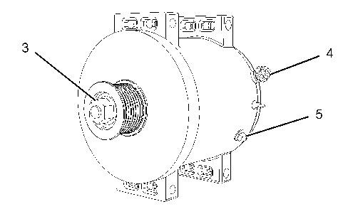
Alternator - Remove and Install
Removal Procedure
Personal injury can result from failure to disconnect the battery.
First, disconnect the negative battery cable. Then, disconnect the positive battery cable.
A positive power lead can cause sparks if the battery is not disconnected. Sparks can possibly result in battery explosion or fire.
Installation Procedure
Copyright 1993 - 2021 Caterpillar Inc. All Rights Reserved. Private Network For SIS Licensees. Thu Dec 9 00:06:14 UTC+0530 2021
Product: EXCAVATOR
Model: 349F L EXCAVATOR BZ2
Configuration: 349F & 349F L Excavators BZ200001-UP (MACHINE) POWERED BY C13 Engine
Disassembly and Assembly
C13 Engine for Caterpillar Built Machines
Media Number -UENR0131-06
Atmospheric Pressure Sensor - Remove and Install
Removal Procedure
Installation Procedure
Note:
i04823628
Product: EXCAVATOR
Model: 349F L EXCAVATOR BZ2
Configuration: 349F & 349F L Excavators BZ200001-UP (MACHINE) POWERED BY C13 Engine
Disassembly and Assembly
C13 Engine for Caterpillar Built Machines
Media Number -UENR0131-06
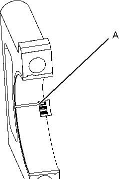
Bearing Clearance - Check
SMCS
Measurement Procedure
NOTICE
Lead wire, shim stock or a dial bore gauge can damage the bearing surfaces.
Note:
Note:

Note:
Product: EXCAVATOR
Model: 349F L EXCAVATOR BZ2
Configuration: 349F & 349F L Excavators BZ200001-UP (MACHINE) POWERED BY C13 Engine
Disassembly and Assembly
C13 Engine for Caterpillar Built Machines
Media Number -UENR0131-06
Belt Tensioner - Remove and Install
Removal Procedure
Installation Procedure
Product: EXCAVATOR
Model: 349F L EXCAVATOR BZ2
Configuration: 349F & 349F L Excavators BZ200001-UP (MACHINE) POWERED BY C13 Engine
Disassembly and Assembly
C13 Engine for Caterpillar Built Machines
Media Number -UENR0131-06
Boost Pressure Sensor - Remove and Install
Removal Procedure
Installation Procedure
Product: EXCAVATOR
Model: 349F L EXCAVATOR BZ2
Configuration: 349F & 349F L Excavators BZ200001-UP (MACHINE) POWERED BY C13 Engine
Disassembly and Assembly
C13 Engine for Caterpillar Built Machines
Media Number -UENR0131-06
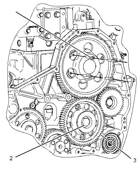
Camshaft - Remove and Install
Removal Procedure
Tool
Updated -27/06/2018
i05331988
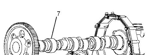

Note:
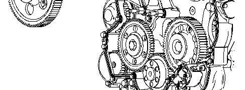
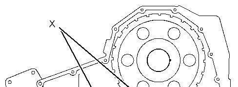
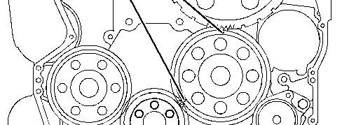
Installation Procedure
NOTICE
When installing the camshaft, make sure the number one cylinder is at top center of the compression stroke with the timing bolt installed in the flywheel. The camshaft timing is very important. The timing mark on the camshaft drive gear must line up with the timing mark on the idler gear. Refer to the Specifications Manual for more information.
Note:
Product: EXCAVATOR
Model: 349F L EXCAVATOR BZ2
Configuration: 349F & 349F L Excavators BZ200001-UP (MACHINE) POWERED BY C13 Engine
Disassembly and Assembly
C13 Engine for Caterpillar Built Machines
Media Number -UENR0131-06
Camshaft Bearings - Remove and Install
Removal Procedure
Required
Tool
i05332615
Start By: