

Product: EXCAVATOR
Model: 345B II EXCAVATOR AGS
Configuration: 345B L Series II Excavators AGS00001-UP (MACHINE) POWERED BY 3176C Engine
Disassembly and Assembly
345B, 345B Series II and W345B Series II Excavators Engine Supplement
Media Number -RENR1043-07
Air Cleaner - Remove and Install
SMCS - 1051-010; 1054-010
Removal Procedure
i01240198
1. Open the front access door on the left side of the machine in order to gain access to the air cleaner.
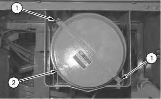
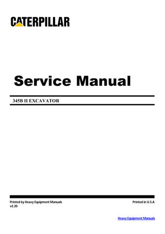
Illustration 1 g00663032
2. Loosen rod assemblies (1). Remove cover assembly (2) .
2
3. Remove primary element (3) .
3
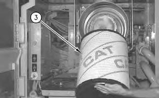
4. Remove secondary element (4) .
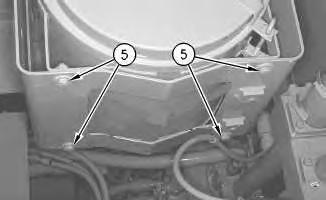
Illustration 4 g00663051
5. Remove bolts (5) and the washers.
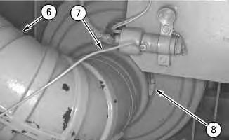
Illustration 5
6. Disconnect tube (7) from the electric indicator.
7. Loosen clamp (8). Remove hose (6) .
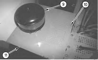
Illustration 6
8. Remove cap assembly (9) .
9. Remove bolts (10). Remove cover (11) .
10. Remove the air cleaner body from the machine.
Installation Procedure
1. Position the air cleaner body on the machine.
7
2. Install cover (11). Install bolts(10) .
3. Install cap assembly (9) .
Illustration 8
4. Install hose (6). Tighten clamp (8) .
5. Connect tube (7) to the electric indicator.

9
6. Install the washers and bolts(5) .
10
7. Install secondary element (4) .
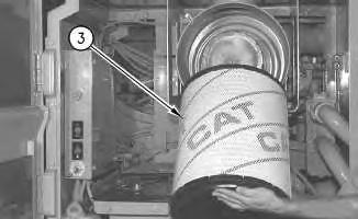
Illustration 11
8. Install primary element (3) .
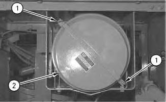
Illustration 12
9. Install cover assembly (2). Tighten rod assemblies (1) .
10. Close the front accessdoor on the left side of the machine. Copyright 1993 - 2021 Caterpillar Inc. All Rights Reserved. Private Network For SIS Licensees. Fri Feb 26 13:20:35 UTC+0530 2021
Product: EXCAVATOR
Model: 345B II EXCAVATOR AGS
Configuration: 345B L Series II Excavators AGS00001-UP (MACHINE) POWERED BY 3176C Engine
Disassembly and Assembly
345B, 345B Series II and W345B Series II Excavators Engine Supplement
Media Number -RENR1043-07
Alternator - Remove and Install
SMCS - 1405-010
Removal Procedure
1. Open the center hood. Lock the center hood in the OPENposition.
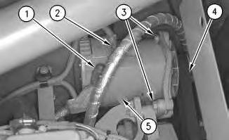
Illustration 1
2. Remove bolts (1). Remove bolts (2) .
Note: Mark all of the wires that are disconnected for installation purposes.
3. Remove the electrical wires from the terminals.
4. Turn the pulley tensioner counterclockwise in order to remove belt (4) .
i01240039
5. Remove bolts (3) from alternator (5) .
6. Remove alternator (5) .
Installation Procedure
Illustration 2
1. Install alternator (5) .
2. Install bolts (3) on the alternator.
g00662832
3. Install belt (4). Turn the pulley tensioner clockwise in order to tighten the belt.
4. Install the electrical wires on the terminals.
5. Tighten the mounting bolt for the ground wire to a torque of 13 ± 1 N·m (10 ± 1 lb ft).
6. Install bolts (1). Install bolts (2) .
7. Close the center hood. Lock the center hood in the CLOSED position.
Copyright 1993 - 2021 Caterpillar Inc. All Rights Reserved. Private Network For SIS Licensees. Fri Feb 26 13:18:13 UTC+0530 2021
Product: EXCAVATOR
Model: 345B II EXCAVATOR AGS
Configuration: 345B L Series II Excavators AGS00001-UP (MACHINE) POWERED BY 3176C Engine
Disassembly and Assembly
345B, 345B Series II and W345B Series II Excavators Engine Supplement
Media Number -RENR1043-07
i01240434
Electric Starting Motor - Remove and Install
SMCS - 1453-010
Removal Procedure
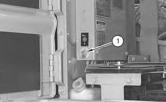
Illustration 1 g00663110
1. Shut off disconnect switch (1). The disconnect switch islocated inside the left panel that is behind the cab.
2. Open the center hood. Lock the center hood in the OPENposition.
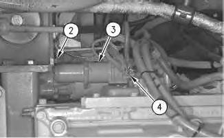
Illustration 2
Note: Mark all of the wires that are disconnected for installation purposes.
3. Disconnect starter terminals (4) .
4. Slide the rubber boot off the starter terminal. Disconnect the two solenoid harnesses.
5. Fasten a lifting sling and a hoist to electric starting motor (3). The weight of the electric starting motor is 24 kg (53 lb).
6. Remove three bolts (2) and the washersthat hold the electric starting motor to the flywheel housing. Carefully remove the electric starting motor and the gasket from the flywheel housing.
Installation Procedure
Illustration 3
1. Fasten a lifting sling and a hoist to electric starting motor (3). The weight of the electric starting motor is 24 kg (53 lb).
2. Install a new gasket on the flywheel housing. Carefully position the electric starting motor on the flywheel housing. Install the washersand three bolts (2) .
3. Connect the two solenoid harnesses. Tighten the solenoid harnesses to a torque of 2 ± .2 N·m (18 ± 2 lb in). Slide the rubber boot on the starter terminal.
4. Connect starter terminals (4) .
5. Close the center hood.

6. Turn disconnect switch (1) to the ON position. The disconnect switch is located inside the left panel that isbehind the cab.
1993 - 2021 Caterpillar Inc.
Product: EXCAVATOR
Model: 345B II EXCAVATOR AGS
Configuration: 345B L Series II Excavators AGS00001-UP (MACHINE) POWERED BY 3176C Engine
Disassembly and Assembly
345B, 345B Series II and W345B Series II Excavators Engine Supplement
Media Number -RENR1043-07
Engine and Main Hydraulic Pump - Install
SMCS - 1024-012
Installation Procedure
Table 1 RequiredTools
i01242082
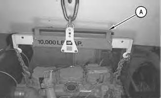
Illustration 1
1. Fasten Tooling (A) and a hoist to the lifting eyes on the engine. The approximate weight of the engine and the main hydraulic pump is 1150 kg (2535 lb).
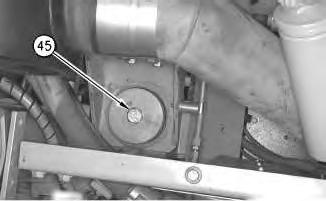
Illustration 2
g00663665
2. Install the washers and mounting bolts(45) in the engine mounts. Tighten the bolts to a torque of 900 ± 100 N·m (664 ± 74 lb ft).
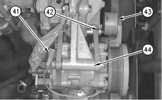
Illustration 3
g00663659
3. Install refrigerant compressor (44). Install bolts (42) on refrigerant compressor (44) .
4. Install the belt on refrigerant compressor (44). Turn belt tensioner (43) clockwise in order to tighten the belt.
5. Connect electrical connector (41) to refrigerant compressor (44) .
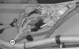
4
6. Connect electrical connector (40) .
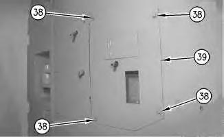
Illustration 5
This is a view underthe rear of the machine.
7. Install sheet assembly (39) on the machine. The weight of the sheet assembly is12 kg (26 lb). Install the washers and bolts(38) .
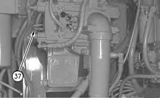
Illustration 6
8. Connect electrical connector (37) to the main hydraulic pump.
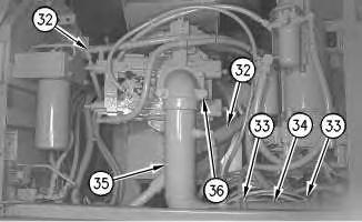
Illustration 7
g00663648
9. Connect tube assembly (35) to the main hydraulic pump. Install the washers and four bolts (36) .
10. Install hose assembly (34) on tube assembly (35). Tighten four clamps (33) .
Note: Make sure that all hydraulic hoses are connected in the correct positions.
11. Connect eight hoses (32) to the main hydraulic pump.
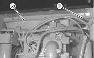
8
12. Install cover (31). Install the washersand the bolts.
13. Install cover (30). Install the washersand the bolts.
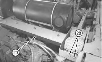
9
14. Install support (29). Install bolts (28) .
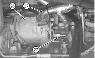
10
15. Connect two hoses (27) to fan drive pump (26) .
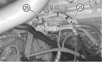
11
16. Connect two fuel hoses (25) to the engine.
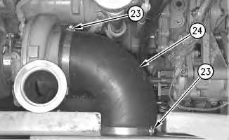
Illustration 12
g00663634
17. Install hose (24). Tighten two clamps (23) .
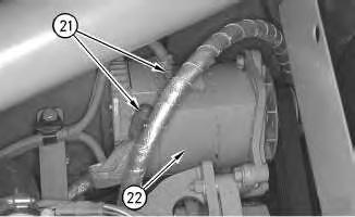
Illustration 13
g00663630
18. Connect electrical connectors(21) to alternator (22) .
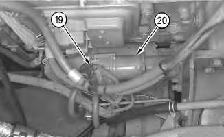
Illustration 14
g00663625
19. Connect electrical connections (19) to starter (20) .
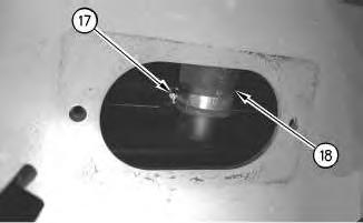
15
20. Connect radiator bottom hose (18) to the radiator.
21. Tighten clamp (17) .
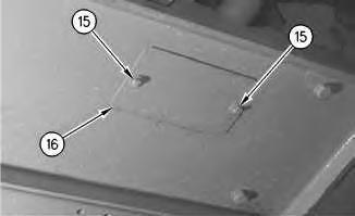
Illustration 16
22. Install cover (16) on the machine. Install the washers and bolts(15) .

23. Connect overflow hose (13) .
24. Install hose (11) on the machine.
25. Install radiator top hose (14) .
26. Connect hose (11) .
27. Tighten two hose clamps (12) on radiator top hose.
28. Install two sheet assemblies (9). Install the washersand bolts (10) .
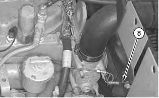
Illustration 19
29. Connect both ends of ether starting aid line (8) .
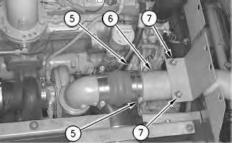
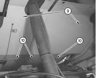
Illustration 20
30. Install tube (6) .
31. Tighten hose clamps (5) on each end of tube (6) .
32. Install the U-bolt. Install the two inside nuts on the U-bolt. Tighten the nuts to a torque of 20 ± 2 N·m (15 ± 1.5 lb ft). Install outside nuts(7). Tighten the nuts to a torque of 50 ± 10 N·m (37 ± 7 lb ft).

Illustration 21
33. Install tube (1) .
34. Tighten hose clamps (3) on each end of tube (1) .
35. Install U-bolt (4). Install the two inside nuts on the U-bolt. Tighten the nuts to a torque of 20 ± 2 N·m (15 ± 1.5 lb ft). Install outside nuts(2). Tighten the nuts to a torque of 50 ± 10 N·m (37 ± 7 lb ft).
36. Fill the radiator with engine coolant. Refer to Operation and Maintenance Manual for the correct procedure to fill the cooling system.
37. Fill the hydraulic system with hydraulic oil. Refer to Operation and Maintenance Manual for the correct procedure to fill the hydraulic system.
End By: Install the engine hood. Refer to Disassembly and Assembly, "Hood - Remove and Install" in this manual.
Product: EXCAVATOR
Model: 345B II EXCAVATOR AGS
Configuration: 345B L Series II Excavators AGS00001-UP (MACHINE) POWERED BY 3176C Engine
Disassembly and Assembly
345B, 345B Series II and W345B Series II Excavators Engine Supplement
Media Number -RENR1043-07
Engine and Main Hydraulic Pump - Remove
SMCS - 1024-011
Removal Procedure
Table 1 RequiredTools Tool
(A) 6V-3145 Load Leveling Beam 1
Start By:
A. Remove the engine hood.
Reference: Refer to Disassembly and Assembly, "Hood - Remove and Install" in this manual.
1. Release the hydraulic system pressure.
i01241786
Reference: Refer to Disassembly and Assembly, "Hydraulic System Pressure - Release"in the machine systems.
NOTICE
Care must be taken to ensure that fluidsare contained during performance of inspection, maintenance, testing, adjusting and repair of the product. Be prepared to collect the fluid with suitable containers before opening any compartment or disassembling any component containing fluids.
Refer to Special Publication, NENG2500, "Caterpillar Tools and Shop Products Guide" for tools and supplies suitable to collect and contain fluids on Caterpillar products.
Dispose of all fluids according to local regulationsand mandates.
At operating temperature, the engine coolant ishot andunder pressure.
Steam can cause personal injury.
Check the coolant level only after the engine hasbeen stopped and the filler cap iscool enoughto touch with the bare hand.
Remove the filler cap slowly to relieve pressure.
Cooling system conditioner contains alkali. Avoid contact with skinand eyes to prevent personal injury.
2. Drain the hydraulic oil from the hydraulic oil tank into a suitable container for storage or disposal. The capacity of the hydraulic oil tank is 370 L (98 USgal).
3. Drain the engine coolant from the cooling system into a suitable container for storage or disposal. The capacity of the cooling system is73 L (19.3 US gal).
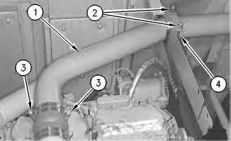
Illustration 1 g00663416
4. Remove four nuts(2). Remove U-bolt (4) .
5. Loosen hose clamps (3) from each end of tube (1) .
6. Remove tube (1) .
Illustration 2
7. Remove four nuts(7) in order to remove the U-bolt.
8. Loosen hose clamps (5) from each end of tube (6) .
9. Remove tube (6) .

Illustration 3
10. Disconnect both ends of ether starting aid line (8) .
Illustration 4
g00663424
11. Remove bolts (10) and the washers. Remove two sheet assemblies (9) .
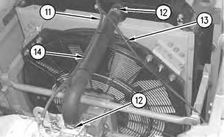
Illustration 5
g00663427
12. Loosen two clamps (12) on radiator top hose (14) .
13. Disconnect hose (11) .
14. Remove radiator top hose (14) .
15. Remove hose (11) from the machine.
16. Disconnect overflow hose (13) .
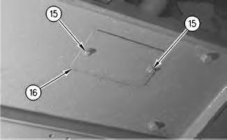
6
17. Remove bolts (15) and the washers. Remove cover (16) from the machine.
7
19. Disconnect radiator bottom hose (18) from the radiator.