Note: Use Bookmarks panel to navigate
This is the sample of the manual click on the download link for complete manual
DOWNLOAD LINK
For some reason if link does not work download this pdf and then click
Product: GENERATOR SET
Model: 3412C GENERATOR SET BCW
Configuration: 3412E Generator Set BCW00001-UP
Disassembly and Assembly
3412C GENERATOR SET ENGINE
Media Number -RENR1389-00
Piston Cooling Jets
SMCS - 1307-011; 1307-012
Remove Piston Cooling Jets
Start By:
a. remove oil pump
1. Turn the crankshaft until pistons are clear of the piston cooling jets to be removed.
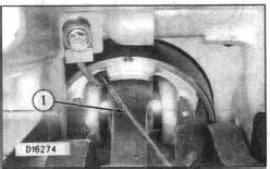
2. Remove screw (1) that holds the piston cooling jets. Remove the piston cooling jets.
Install Piston Cooling Jets
RENR13890060
NOTE: If the piston cooling jets are to be reused, check the alignment of the piston cooling jet with tooling (A). See Special Instructions, Form No. SMHS7267, for instructions on the use of the piston cooling jet alignment tool group.
1. Position the piston cooling jet on the cylinder block, and install the screw that holds the cooling jet to the block.
2. Tighten the screw to a torque of 24 ± 7 Nm (18 ± 5 lb ft).
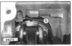
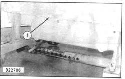
3. With the piston at the bottom of the bore, check the clearance between piston and piston cooling jet with a piece of wire (1) 0.63 mm (.025 in) thick. If the clearance is less than 0.63 mm (.025 in), make a replacement of the tube.
NOTE: The piston cooling jets must fit evenly against the cylinder block. If the piston cooling jets do not, this misalignment will cause an oil loss in the engine oil system.
End By: a. install oil pump
Product: GENERATOR SET
Model: 3412C GENERATOR SET BCW
Configuration: 3412E Generator Set BCW00001-UP
Disassembly and Assembly
3412C GENERATOR SET ENGINE
Media Number -RENR1389-00 Publication Date -01/03/1998
Oil Pump
SMCS - 1304-016; 1304-010; 1304-015
Remove & Install Oil Pump
Start By:
a. remove oil pan
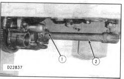
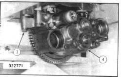
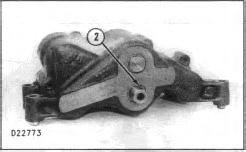
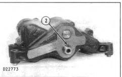
1. Remove bolt (1) and tube (2) from the oil pump.
-11/01/2016
RENR13890059
2. Remove three bolts (3) that hold the pump in position on the block. Remove oil pump (4).
NOTE: The following steps are for installing the oil pump.
3. Install oil pump (4) and the three bolts (3) that hold it in place.
4. Make sure the O-ring seal is in position on tube (2). Install tube (2) on the oil pump. Install the one bolt (1) that holds the tube to the pump.
End By:
a. install oil pan
Disassemble Oil Pump
Start By:
a. remove oil pump
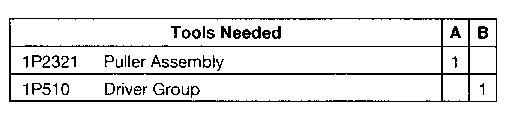
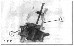
1. Remove the bolt and washer that hold gear (1) in position on the shaft. Remove gear with tool (A).
2. Remove key (2) from the shaft.
Typical Example.
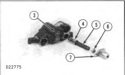
3. Remove the bolts and retainer (7). Remove spacer (6), spring (5), and plunger (4) from the oil pump.
NOTE: The 6N1030 Oil Pump does not have spacer (6).
4. Remove bolts and cover (3).
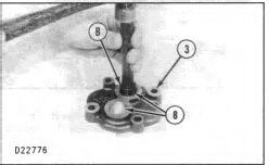
5. Use tooling (B) to remove two bearings (8) from cover (3).
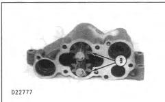
6. Remove two shaft assemblies (9) from the pump body.
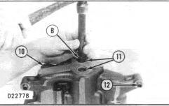
7. Use tooling (B) to remove two bearings (11) from pump body (10). Remove two dowels (12) from the pump body.
Assemble Oil Pump
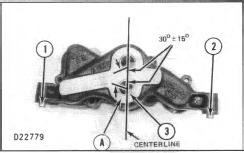
1. Use tooling (A) to install two bearings (3) in the pump body. The bearing joint must be within 30 ± 15 degrees of a centerline through the bores as shown. The bearings must be installed so they are even with face (A).
2. Install dowels (1) and (2) in the pump body. Install the dowels so each extends 6.40 mm (.252 in) above the surface.
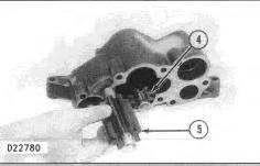
3. Put clean oil on the inside diameter of the bearings in the pump body and on shafts (4) and (5).
4. Install shaft (4) in the lower section of the pump, as shown. Shaft (4) has the groove (slot) for the key.
5. Install shaft (5).
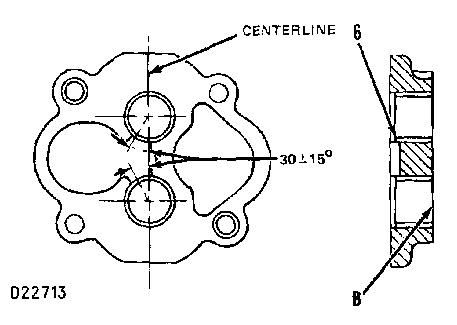
6. Use tooling (A) to install two bearings (6) in the cover. The bearing joint in the bearing must be 30 ± 15 degrees from the centerline through the bores, as shown.
7. Install the bearings so each bearing is even with face (B). Put clean oil on the inside diameter of each bearing.
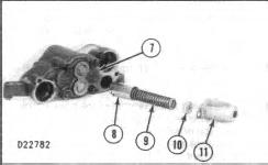
8. Install cover (7) on the pump body. Install plunger (8), spring (9), spacer (10), and retainer (11) on the pump. Install the bolts that hold the retainer.
NOTE: The 6N1030 Oil Pump does not have spacer (10).
9. Install key (12) in the shaft.
Typical Example.
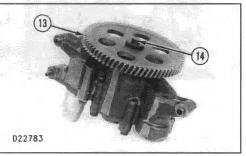
10. Install gear (13), the washer, and bolt (14). Tighten the bolt to a torque of 54 ± 7 N·m (40 ± 5 lb ft).
11. The pump must turn freely after the pump is assembled.
End By:
a. install oil pump
Copyright 1993 - 2024 Caterpillar Inc. All Rights Reserved. Private Network For SIS Licensees.
Product: GENERATOR SET
Model: 3412C GENERATOR SET BCW
Configuration: 3412E Generator Set BCW00001-UP
Disassembly and Assembly
3412C GENERATOR SET ENGINE
Media Number -RENR1389-00 Publication Date -01/03/1998 Date Updated -11/01/2016
Oil Pan
SMCS - 1302-011; 1302-012
Remove Oil Pan
1. Drain the oil from the oil pan.
RENR13890058
2. Remove bolts (1) from around the oil pan. Remove the oil pan. The weight of the oil pan is 27 kg (60 lb).
Install Oil Pan
1. Put a new gasket into position on the oil pan. Put the oil pan into position on the engine.
2. Install the bolts that hold pan (1) to the cylinder block.
Copyright 1993 - 2024 Caterpillar Inc. All Rights Reserved.
Private Network For SIS Licensees. Tue Mar 26 22:47:52 UTC+0530 2024
Product: GENERATOR SET
Model: 3412C GENERATOR SET BCW
Configuration: 3412E Generator Set BCW00001-UP
Disassembly and Assembly
3412C GENERATOR SET ENGINE
Media Number -RENR1389-00
Oil Cooler
SMCS - 1378-011; 1378-012
Remove Oil Cooler
Start By:
a. remove oil filter base
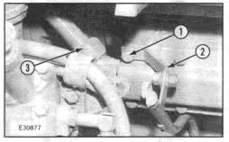
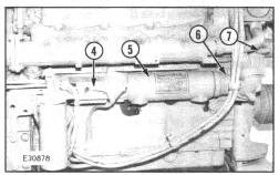
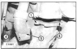
1. Remove bolt (1) to disconnect bracket (2) from the bonnet.
2. Remove the bolts, bonnet (4), the gasket between the bonnet, and core assembly (5) from bonnet (6).
3. Remove two bolts that hold the elbow to bonnet (6). Remove the four bolts and bonnet (6) from water pump (7).
RENR13890057
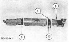
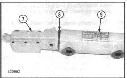
4. Remove adapter (8) from bonnet (6). Remove O-ring seals (9) and (10).
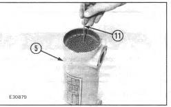
5. Use a 3.20 mm (.125 in) diameter rod (11) to make sure the tubes in core assembly (5) are clean.
Install Oil Cooler
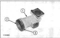
1. Install two O-ring seals (3) on adapter (2). Put clean engine oil or glycerine on each seal. Install adapter (2) in bonnet (1).
2. Install gasket (6) and bonnet (1) on the water pump. Install the bolt that holds elbow (5) to bonnet (1). Install the bolt that holds clip (4) to elbow (5).
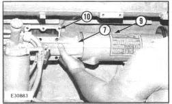
3. Install O-ring seal (8) on bonnet (7). Put clean engine oil or glycerine on the seal. Install bonnet (7) in core assembly (9).
4. Make sure gasket (10) is in position on the engine block. Install bonnet (7) and core assembly (9) as a unit.
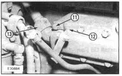
5. Install bolt (11) that holds bracket (12) in position against the bonnet.
End By: a. install oil filter base Copyright 1993 - 2024 Caterpillar Inc. All Rights Reserved. Private Network For SIS Licensees.
Product: GENERATOR SET
Model: 3412C GENERATOR SET BCW
Configuration: 3412E Generator Set BCW00001-UP
Disassembly and Assembly
3412C GENERATOR SET ENGINE
Media Number -RENR1389-00
Oil Filter Base
SMCS - 1306-010
Remove & Install Oil Filter Base
-01/03/1998
Updated -11/01/2016
RENR13890056
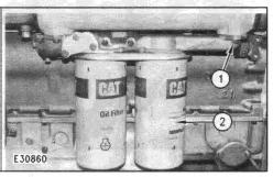
1. Remove the oil filters (1) with tool A.
2. Remove mounting bolts (1).
3. Remove the oil filter base and the gaskets.
4. Use new gaskets, install in reverse order. Copyright 1993 - 2024 Caterpillar Inc.
Product: GENERATOR SET
Model: 3412C GENERATOR SET BCW
Configuration: 3412E Generator Set BCW00001-UP
Disassembly and Assembly
3412C GENERATOR SET ENGINE
Media Number -RENR1389-00
Oil Bypass Valve
SMCS - 1378-010
-01/03/1998
-11/01/2016
RENR13890055
Remove & Install Oil Bypass Valves
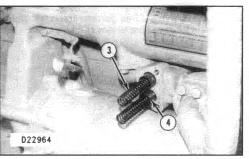
There are two springs under compression behind cover (2). To prevent personal injury, hold cover (2) as three bolts (1) are removed.
1. Remove three bolts (1) and cover (2).
2. Remove two springs and plungers.
3. Put clean engine oil on two plungers at installation. Install in reverse order.
Copyright 1993 - 2024 Caterpillar Inc. All Rights Reserved. Private Network For SIS Licensees.
Tue Mar 26 22:47:19 UTC+0530 2024
Product: GENERATOR SET
Model: 3412C GENERATOR SET BCW
Configuration: 3412E Generator Set BCW00001-UP
Disassembly and Assembly
3412C GENERATOR SET ENGINE
Media Number -RENR1389-00 Publication Date -01/03/1998 Date Updated -11/01/2016
Fuel Shutoff Solenoid
SMCS - 1259-010
Remove & Install Fuel Shutoff Solenoid
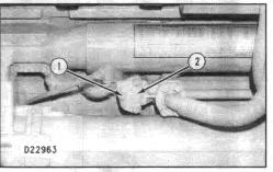
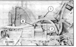
1. Disconnect connector (1).
RENR13890054
2. Use tooling (A) to remove solenoid (2). Torque solenoid (2) to 70 ± 10 N·m (50 ± 7 lb ft).
3. Install in reverse order.
Copyright 1993 - 2024 Caterpillar Inc. All Rights Reserved. Private Network For SIS Licensees. Tue Mar 26 22:47:06 UTC+0530 2024
Product: GENERATOR SET
Model: 3412C GENERATOR SET BCW
Configuration: 3412E Generator Set BCW00001-UP
Disassembly and Assembly
3412C GENERATOR SET ENGINE
Media Number -RENR1389-00
Governor (Dashpot Governor)
SMCS - 1264-011; 1264-012
Remove Governor (Dashpot Governor)
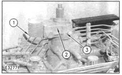
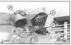
1. Remove cover (1), plate assembly (2), and adapter group (3) from the governor.
RENR13890053
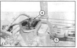
2. Remove the bolt that holds collar (4) on the bolt. Remove cover (5) and the spring under the collar.
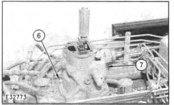
3. Remove bolts (6) and governor housing (7). Remove the gasket that is under the governor housing.
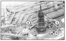
4. Disconnect two fuel lines (8) from the plate group. Remove seat (9) and spring (10).
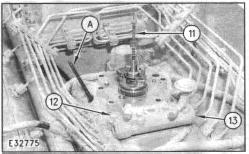
5. Remove bolts (12) that hold the plate group (13) on the fuel injection pump housing. Remove the plug from the side of the fuel injection pump housing and install tooling (A).
6. Pull the bolt (11) up to put the rack in the center position. The rack is in the center position when it is against tool (A).
7. Remove adapter group (13).
NOTE: Keep bolt (11) pulled up to keep the rack in the center position. If the rack is not in the center position, the lever on the bottom of the plate group will prevent the plate group from being removed from the fuel injection pump housing.
Install Governor (Dashpot Governor)
NOTICE
Do not install the plate group until drive assembly (3) is removed from the plate group.
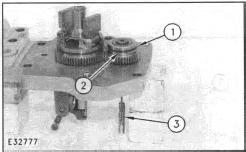
1. Remove ring (1), dowel (2), and drive assembly (3) from the plate group.
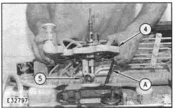
2. Install tool (A) in the side of the fuel injection pump housing. Move the rack against tool (A). This puts the rack in the center position.
NOTE: The fuel rack must be in the center position so lever (5) can be put in alignment with the groove (slot) in the rack. A small amount of force on the end of tool (A) will be needed to keep the rack in the center position.
3. Install plate group (4) on the fuel injection pump housing. Make sure lever (5) aligns with the groove (slot) in the rack. Remove tool (A).
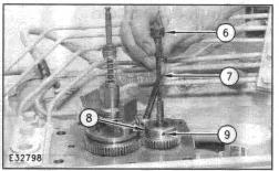
4. Install drive assembly (7) in the drive group. Make sure that the groove in the bottom of the drive assembly is in alignment with the pin in the pinion in the fuel injection pump housing. Make sure hole (6) and hole (9) in gear (8) are in alignment.
5. Install pin (11) that holds drive assembly (7) in position in gear (8).
6. Install ring (10) to hold pin (11) in position in the gear.
7. Connect two fuel lines (12) to the plate group.
8. Install spring (14) and seat (13).
9. Install gasket (16) and governor housing (15). Install the bolts that hold it in place.
10. Install spring (18) and collar (17) on bolt (19). Install the bolt that holds the collar on bolt (19).
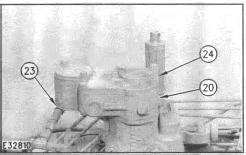
11. Install gasket (22) and adapter group (20) on the governor housing. Make sure lever (21) is in position under collar (17).
12. Put the gasket and plate assembly (24) in position on adapter group (20). Make sure the pin on plate assembly (24) is in the groove (slot) in the collar.
13. Install the gaskets and two covers (23) on the plate assembly.
14. Check the governor adjustment. See "Governor Adjustments" in the Testing and Adjusting manual.
Product: GENERATOR SET
Model: 3412C GENERATOR SET BCW
Configuration: 3412E Generator Set BCW00001-UP
Disassembly and Assembly
3412C GENERATOR SET ENGINE
Media Number -RENR1389-00
Governor & Fuel Injection Pump Housing
SMCS - 1255-010; 1255-015; 1255-016; 1264; 1268
Updated -11/01/2016
RENR13890052
Remove & Install Governor & Fuel Injection Pump Housing
Start By:
a. remove fuel injection lines
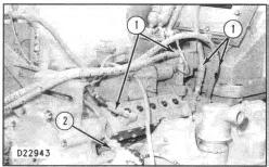
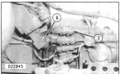
1. Disconnect four fuel lines (1).
2. Disconnect connector (2).
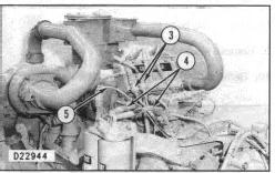
3. Disconnect two fuel lines (4).
4. Remove wire (5).
5. Disconnect two connectors (3).
6. Disconnect hose (6).
7. Disconnect four connectors (7).
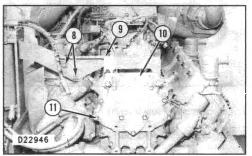
8. Remove two bolts (8).
9. Remove eleven bolts (11).
10. Remove bracket (9) and cover (10) together.
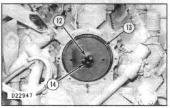
11. Remove four bolts (14) and spacer (12). At assembly, torque bolts (14) for 5/8" bolts to 230 ± 15 N·m (170 ± 11 lb ft) or for 1/2" bolts to 136 ± 7 N·m (100 ± 5 lb ft).
12. Remove drive gear assembly (13).
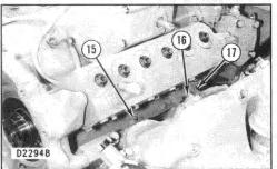
13. Remove three bolts (15).
14. Remove bolt (16).
15. Remove bracket (17).
16. Remove tube (18).
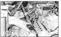
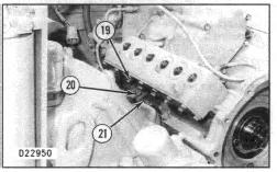
17. Remove three bolts (21).
18. Remove bolt (20) and bracket (19).
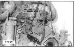
19. Attach a hoist to pump (22) as shown. Remove the pump. The weight of the pump is 91 kg (200 lb).
NOTE: Reverse the order of Steps 1 thru 19 for installation.
End By:
a. install fuel injection lines
Disassemble Governor & Fuel Injection Pump Housing
This is the sample of the manual click on the download link for complete manual
DOWNLOAD LINK
For some reason if link does not work download this pdf and then click