CAT Caterpillar 3406C Service Repair Manual PDF Download
Note: Use Bookmarks panel to navigate
This is the sample of the manual click on the download link for complete manual
DOWNLOAD LINK
For some reason if link does not work download this pdf and then click
Product: MARINE ENGINE
Model: 3406C MARINE ENGINE 1SS
Configuration: 3406C Marine Auxiliary and Generator Set 1SS00001-UP
Disassembly and Assembly
3406C MARINE ENGINE
SENR11430016
Accessory Drive
SMCS - 1206-011; 1206-012; 1206-015; 1206-016
Remove Accessory Drive
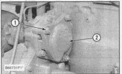
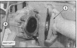
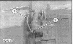
1. Remove nuts (1), cover (2) and the gasket from the accessory drive.
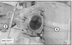
2. Remove bolts (3), accessory drive (4) and the gasket from the front timing gear plate.
Install Accessory Drive
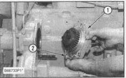
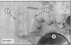
1. Put gasket (2) and accessory drive (1) in position on the front timing gear plate and install the bolts that hold them. Make sure the accessory drive gear is in alignment with the camshaft gear.
2. Put gasket (4) and cover (3) in position on the accessory drive and install the nuts that hold them
Disassemble Accessory Drive
Start By:
a. remove accessory drive
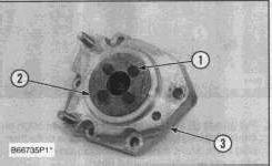
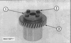
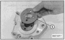
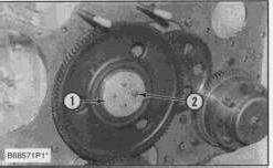
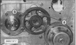
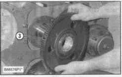
1. Remove bolts (1), plate (2) that hold the gear to the bearing.
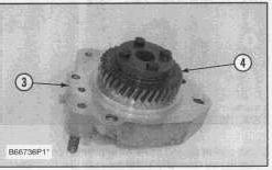
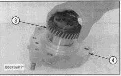
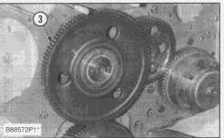
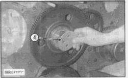
2. Remove gear (4) from bearing (3).
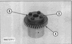
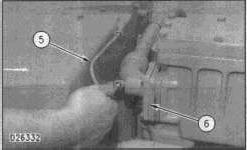
3. Remove bolts (5), cover (6) from gear (4).
Assemble Accessory Drive
1. Install cover (1) and bolts (2) on gear (3).
2. Install gear (3) in bearing (4) as shown.
3. Install cover (5) and the bolts that hold the gear in the bearing.
End By:
a. install accessory drive
Copyright 1993 - 2024 Caterpillar Inc.
All Rights Reserved.
Private Network For SIS Licensees.
Mon May 27 22:29:01 UTC+0530 2024
Product: MARINE ENGINE
Model: 3406C MARINE ENGINE 1SS
Configuration: 3406C Marine Auxiliary and Generator Set 1SS00001-UP
Disassembly and Assembly
3406C MARINE ENGINE
Aftercooler Housing
SMCS - 1063-011; 1063-012
Remove Aftercooler Housing
Start By:
a. remove fuel filter base
FLUID SPILLAGE CONTAINMENT
Care must be taken to ensure that fluids are contained during performance of inspection, maintenance, testing, adjusting and repair of the machine. Be prepared to collect the fluid with suitable containers before opening any compartment or disassembling any component containing fluids. Refer to "TOOLS AND SHOP PRODUCT GUIDE, NENG2500", for tools and supplies suitable to collect and contain fluids in Caterpillar machines. Dispose fluids according to local regulations and mandates.
1. Drain the coolant from the engine into a suitable container for storage or disposal.
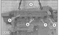
2. Remove tube (1). Cap and plug all openings immediately.
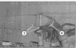
3. Remove the four bolts and washers that hold adapter (2) to the aftercooler housing. Move the elbow away from the aftercooler housing.
4. Remove five bolts and washers (3) that hold air inlet pipe (4) to the aftercooler housing. Move the air inlet pipe away from the aftercooler housing.
5. Disconnect tube assembly (7).
6. Fasten a hoist and Tool (A) to aftercooler housing (5). Remove twelve bolts (6), that hold aftercooler housing (5) to the cylinder head and remove the aftercooler housing. The weight of the aftercooler housing is 34 kg (75 lb)
7. Remove the six gaskets from the cylinder head.
8. Remove the O-ring seal from the water outlet tube (8).
Install Aftercooler Housing
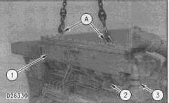
1. Put the six gaskets in place on the cylinder head.
2. Put a new O-ring seal in position on pipe (3). Put clean oil on the O-ring seal.
3. Fasten a hoist and Tool (A) to aftercooler housing (1).
4. Put the aftercooler housing in position on the elbow and cylinder head.
5. Put 9S-3263 Thread Lock on the threads of the bolts, and install the bolts that hold aftercooler housing (1) to the cylinder head.
6. Connect tube assembly (2) to the aftercooler housing.
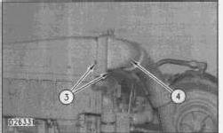
7. Put the gasket and air inlet pipe (4) in position on the aftercooler, and install five bolts (3) that hold the air inlet pipe to the aftercooler housing.
8. Put the gasket and elbow (6) in position on the aftercooler housing, and install the four bolts that hold them in place.
9. Install tube (5).
10. Fill the engine with coolant to the correct level. See the Operation & Maintenance Manual.
End By:
a. install fuel filter base
Product: MARINE ENGINE
Model: 3406C MARINE ENGINE 1SS
Configuration: 3406C Marine Auxiliary and Generator Set 1SS00001-UP
Disassembly and Assembly
3406C MARINE ENGINE
SENR11430004
Air Cleaner
SMCS - 1051-010
Remove & Install Air Cleaner
1. Remove three bolts (1).
2. Loosen hose clamp (2).
3. Remove three bolts (4), and remove air cleaner (3).
NOTE: The following steps are for installation of the air cleaner.
4. Put air cleaner (3) in position on the turbocharger and bracket.
5. Install three bolts (4) that hold the air cleaner to the bracket. Tighten bolts (4) to a torque of 25 ± 7 N·m (18 ± 5 lb ft)
6. Tighten hose clamp (2) to a torque of 4.5 ± 0.5 N·m (39.82 ± 4.42 lb in).
7. Install three bolts (1). Tighten bolts (1) to a torque of 25 ± 7 N·m (18 ± 5 lb ft)
Product: MARINE ENGINE
Model: 3406C MARINE ENGINE 1SS
Configuration: 3406C Marine Auxiliary and Generator Set 1SS00001-UP
Disassembly and Assembly
3406C MARINE ENGINE
Bridge Dowels
SMCS - 1121-012; 1121-011
Remove Bridge Dowels
Start By: a. remove valves
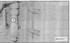
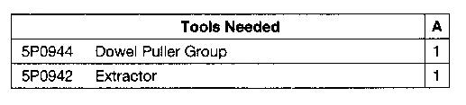
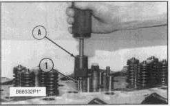
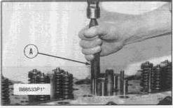
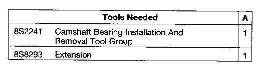
1. Use Tooling (A) to remove bridge dowel (1).
Install Bridge Dowels
1. Use Tool (A) to install the bridge dowel.
End By:
a. install valves
Copyright 1993 - 2024 Caterpillar Inc. All Rights Reserved. Private Network For SIS Licensees.
Mon May 27 22:46:10 UTC+0530 2024
Product: MARINE ENGINE
Model: 3406C MARINE ENGINE 1SS
Configuration: 3406C Marine Auxiliary and Generator Set 1SS00001-UP
Disassembly and Assembly
3406C MARINE ENGINE
SENR11430054
Camshaft Bearings
SMCS - 1211-011; 1211-012
Remove Camshaft Bearings
Start By:
a. remove camshaft
b. remove flywheel housing
c. remove pistons and connecting rod assemblies
d. remove timing gears and plate
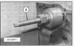
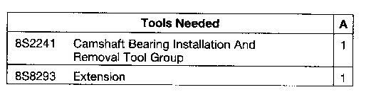
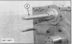
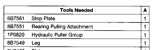
1. Use Tool (A) to remove the camshaft bearings from the cylinder block starting with the rear bearing.
Install Camshaft Bearings
1. Use Tooling (A) to install the camshaft bearings in the cylinder block.
2. All camshaft bearings must be installed so that the holes in the bearings are 90 ± 15 degrees from the oil holes in the cylinder block. Make sure the bearing joint position is above the oil holes.
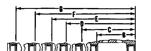
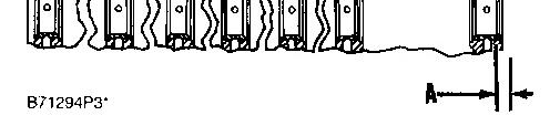
3. The installation depth of dimension A of the front bearing from the front face of the block is 2.8 ± 0.5 mm (.11 ± .02 in).
4. Install the remainder of the bearings to the dimensions given from the front face of the block:
B. 181.9 ± 0.5 mm (7.16 ± .02 in).
C. 353.3 ± 0.5 mm (13.91 ± .02 in).
D. 524.8 ± 0.5 mm (20.66 ± .02 in).
E. 696.2 ± 0.5 mm (27.41 ± .02 in).
F. 867.7 ± 0.5 mm (34.16 ± .02 in).
G. 1039.1 ± 0.5 mm (40.91 ± .02 in).
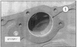
5. After assembly, the inside diameter of bearings (1) must be 69.969 ± 0.048 mm (2.7500 ± .0019 in). The remainder of the bearing must have an inside diameter of 69.982 ± 0.061 mm (2.7552 ± .0024 in)
End By:
a. install timing gears and plate
b. install pistons and connecting rod assemblies
c. install flywheel housing
Product: MARINE ENGINE
Model: 3406C MARINE ENGINE 1SS
Configuration: 3406C Marine Auxiliary and Generator Set 1SS00001-UP
Disassembly and Assembly
3406C MARINE ENGINE
Camshaft
SMCS - 1210-011; 1210-012
Remove Camshaft
Start By:
a. remove timing gear cover
b. remove valve lifters
FLUID SPILLAGE CONTAINMENT
Care must be taken to ensure that fluids are contained during performance of inspection, maintenance, testing, adjusting and repair of the machine. Be prepared to collect the fluid with suitable containers before opening any compartment or disassembling any component containing fluids. Refer to "TOOLS AND SHOP PRODUCT GUIDE, NENG2500", for tools and supplies suitable to collect and contain fluids in Caterpillar machines. Dispose fluids according to local regulations and mandates.
1. Turn the engine to top center compression stroke for the No. 1 piston.
2. Remove four bolts (2) and plate (1) that hold the idler gear in place.
3. Remove idler gear (3).
4. Remove two bolts (4) and retainer (5) that hold the camshaft to the cylinder block.
5. Carefully remove the camshaft assembly from the cylinder block.
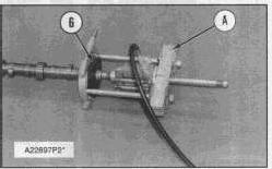
6. Remove camshaft gear (6) from the camshaft with Tooling (A).
Install Camshaft
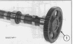
1. Heat camshaft gear (1) to a maximum temperature of 315°C (600°F)
2. Put the key in the camshaft in alignment with the groove (keyway) in gear (1). Install gear (1) on the camshaft.
3. Put clean engine oil on the lobes and journals of the camshaft.
4. Carefully install camshaft assembly (2) in the cylinder block.
5. Install the retainer that holds the camshaft in the cylinder block.
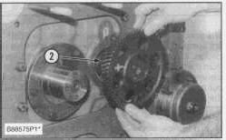
6. Install idler gear (3) on its shaft. Be sure the "V" mark on idler gear (3) is in alignment with the "V" mark on the crankshaft gear. The "K" marks on the camshaft gear can be seen at the edge of the idler gear.
7. Install plate (4) and the bolts that hold the idler gear in place.
NOTE: It will be necessary to check the timing of the governor and fuel pump drive. See the topic "Camshaft Timing For Fuel Injection Pump" in Systems Operation Testing & Adjusting Manual.
End By:
a. install valve lifters
b. install timing gear cover Copyright 1993 - 2024 Caterpillar Inc. All Rights Reserved.
Network For SIS Licensees. Mon May 27 22:50:21 UTC+0530 2024
Product: MARINE ENGINE
Model: 3406C MARINE ENGINE 1SS
Configuration: 3406C Marine Auxiliary and Generator Set 1SS00001-UP
Disassembly and Assembly
3406C MARINE ENGINE
Connecting Rod Bearings
SMCS - 1219-010
Remove & Install Connecting Rod Bearings
Start By:
a. remove oil pump
1. Check the connecting rods and caps for their identification and location.
2. Turn the crankshaft until the connecting rod caps are in position.
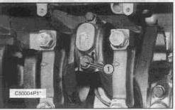
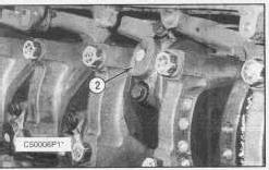
3. Remove two bolts (1) and the cap from the connecting rod. Remove the lower half of the bearing from the cap.
4. Push the connecting rod away from the crankshaft. Remove the upper half of the bearing from the connecting rod.
NOTE: Install the bearings dry when the clearance checks are made. Put clean engine oil on the bearings for final assembly.
5. Install the upper half of the bearing in the connecting rod.
6. Pull the connecting rod slowly on to the crankshaft.
7. Install the lower half of the bearing in the cap.
NOTICE
Be sure the tabs in the back of bearings are in the tab grooves of the connecting rod and cap. The serviceman must be very careful to use Plastigage, Tool (A) correctly. The following points must be remembered.
...Make sure that the backs of the bearings and bores are clean and dry.
...Make sure that the bearing locking tabs are properly seated in their slots.
The crankshaft must be free of oil where the Plastigage touches it.
...Put a piece of Plastigage (A) on the crown o bearing half that is in the cap. Do not allow the Plastigage to extend over the edge of the bearing.
...Install the bearing cap using the correct torque-tur specifications. Do not use an impact wrench. Be careful not to dislodge the bearing when the cap is installed.
Do not turn the crankshaft with the Plastigage installed.
Carefully remove the cap but do not remove the Plastigage. Measure the width of the Plastigage while it is in the bearing cap or on the crankshaft journal. Do this by using the correct scale on the package. Record the measurements.
Remove the Plastigage before reinstalling the cap.
When using Plastigage, the readings can sometimes be unclear. For example, all parts of the Plastigage are not the same width. Measure the major widths to make sure that they are within the specification range. Also, experience has shown that when checking clearances tighter than 0.10 mm (.004 in) the readings may be low by 0.013 to 0.025 mm (.0005 to .0010 in). Out-of-round journals can give faulty readings. Also, journal taper may be indicated when one end of the Plastigage is wider than the other.
For complete details concerning measuring bearing clearances. See Engine Bearings and Crankshafts, SEBD0531.
8. Use Plastigage (A) to check the bearing clearance.
9. Put Plastigage (A) on the bearing.
10. Put 4C-5593 Thread Lubricant on the threads of the rod bolts and seat surfaces of the nuts.
NOTE: Be sure the cylinder numbers on the rod cap and rod are the same and are on the same side of connecting rod. Numbers are on the same side of the rod and cap as are the bearing tab slots. If new rods are installed, put the cylinder number on the rod and cap.
NOTE: Do not turn the crankshaft when Plastigage (A) is in position.
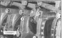
11. Install rod caps (2). Install the two bolts. Tighten each bolt to a torque of 90 ± 8 N·m (67 ± 6 lb ft). Put a mark on the nuts and cap, and tighten the nuts an extra 90 ± 5 degrees from the mark.
Remove the rod cap. Remove Plastigage (A), and check the bearing clearance. The bearing clearance must be 0.071 to 0.168 mm (.0028 to .0066 in) for new bearings. Maximum clearance with used bearings is 0.25 mm (.010 in).
12. Put clean engine oil on lower half of the bearing. Install the rod cap again. Tighten each nut to a torque of 90 ± 8 N·m (67 ± 6 lb ft). Put a mark on the nuts and cap, and tighten the nuts an extra 90 ± 5 degrees from mark.
13. Do steps 1 through 12 for the remainder of the connecting rod bearings.
End By:
a. install oil pump
This is the sample of the manual click on the download link for complete manual
DOWNLOAD LINK
For some reason if link does not work download this pdf and then click