

Product: EXCAVATOR
Model: 336E LH EXCAVATOR RZA
Configuration: 336E LH & 336E LNH (Hybrid) Excavators RZA00001-UP (MACHINE) POWERED BY C9.3 Engine
Disassembly and Assembly C9.3
Engines for Caterpillar Built Machines
Media Number -KENR8149-07
Air Cleaner Housing - Remove and Install
SMCS - 1051-010
Removal Procedure
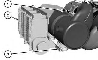
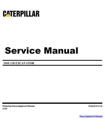
Illustration 1 g01950245
1. Remove bolts (3) and remove bolts (1).
-29/05/2014
i03634657
2. Use two people in order to remove the air cleaner housing (2) from the machine. The weight of the air cleaner housing isapproximately 20 kg (44 lb).
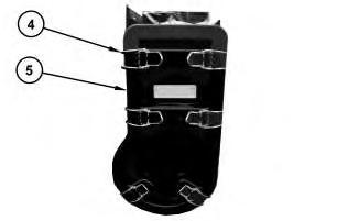
Illustration 2
3. Release spring clips(1) and remove cover (2).
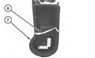
Illustration 3
g01950251
4. Remove primary air filter (6) from housing (7).
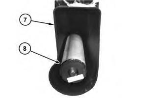
Illustration 4
g01950255
5. Remove secondary air filter (8) from housing (7).
Copyright 1993 - 2020 Caterpillar Inc.
Product: EXCAVATOR
Model: 336E LH EXCAVATOR RZA
Configuration: 336E LH & 336E LNH (Hybrid) Excavators RZA00001-UP (MACHINE) POWERED BY C9.3 Engine
Disassembly and Assembly C9.3
Engines for Caterpillar Built Machines
Media Number -KENR8149-07
Air Compressor - Remove and Install
SMCS - 1803-010
Removal Procedure
Do not disconnect the air linesuntil the air pressure in the system is at zero. If hose is disconnected under pressure it can cause personal injury.
NOTICE
Keep all parts clean from contaminants.
Contaminants may cause rapid wear and shortened component life.
NOTICE
Care must be taken to ensure that fluidsare contained during performance of inspection, maintenance, testing, adjusting, andrepair of the product. Be prepared to collect the fluid with suitable containers
before opening any compartment or disassembling any component containing fluids.
Refer to Special Publication, NENG2500, "Dealer Service Tool Catalog" for tools andsupplies suitable to collect andcontainfluids on Cat® products.
Dispose of all fluids according to local regulationsand mandates.
1. Ensure that the No. 1 cylinder isat the top center compression stroke. Refer to Testing and Adjusting, "Finding Top Center Position for No. 1 Piston".
2. Remove the air pressure from the air tank.
3. Drain the coolant from the cooling system into a suitable container for storage or for disposal. Refer to Operation and Maintenance Manual, "Cooling System Coolant (ELC) - Change".
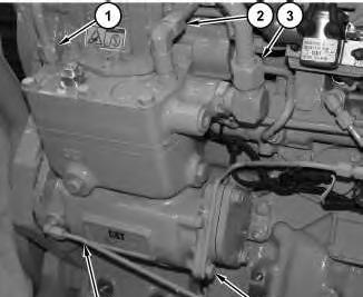
4. Disconnect tube assembly (1), tube assembly (2), tube assembly (3), and tube assembly (4).
5. Remove clamp assembly (5).
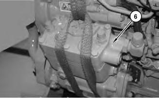
Illustration 2
g01356660
6. Attach a suitable lifting device onto air compressor (6). The weight of air compressor (6) is approximately 32 kg (70 lb).
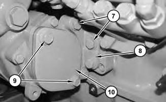
Illustration 3
g01356872
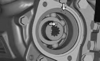
Illustration 4
g01271799
7. Remove bolts (9) and cover (10). Ensure that the timing mark on the crankshaft of the compressor is positioned between the timing marks on the housing for the compressor. Reinstall cover (10) and bolts (9). Remove bolts (7). Remove bracket (8).
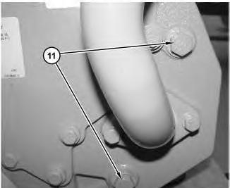
Illustration 5
g01356874
8. Remove bolts (11). Remove the air compressor and the O-ring seal from the engine.
Installation Procedure
1. Ensure that the No. 1 cylinder isat the top center compression stroke. Refer to Testing and Adjusting, "Finding Top Center Position for No. 1 Piston".
Illustration 6
g01356660
Note: Check the O-ring seal for wear or for damage. If necessary, replace the O-ring seal.
2. Attach a suitable lifting device onto air compressor (6). The weight of air compressor (6) is approximately 32 kg (70 lb). Position the O-ring seal and air compressor (6) onto the engine.
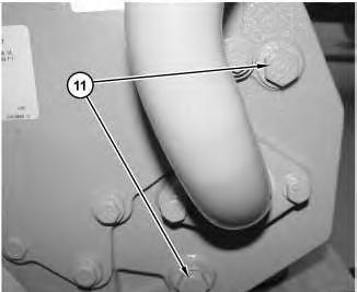
Illustration 7
3. Install bolts (11).
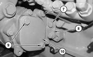
Illustration 8

9
4. Remove bolts (9) and cover (10). Ensure that the timing mark on the crankshaft of the compressor is positioned between the timing marks on the housing for the compressor. Install cover (10) and bolts (9). Install bracket (8). Install bolts(7).
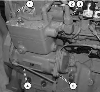
Illustration 10
g01356642
Note: Removal of the timing pin is necessary prior to connecting tube assembly (4).
5. Connect tube assembly (4), tube assembly (3), tube assembly (2), and tube assembly (1).
6. Install clamp assembly (5).
7. Fill the cooling system with coolant. Refer to Operation and Maintenance Manual, "Cooling System Coolant (ELC) - Change.".
Mon Oct 12 10:16:58 UTC+0530 2020
Product: EXCAVATOR
Model: 336E LH EXCAVATOR RZA
Configuration: 336E LH & 336E LNH (Hybrid) Excavators RZA00001-UP (MACHINE) POWERED BY C9.3 Engine
Disassembly and Assembly C9.3
Engines for Caterpillar Built Machines
Media Number -KENR8149-07
Air Control Valve - Remove and Install - Control Module, Clean Emissions Module
SMCS - 108A-010
Removal Procedure
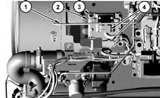
Illustration 1
1. Remove tube assembly (1) and disconnect harness assemblies(4) .
2. Remove bolts (3) and remove Control Module (2) .
Installation Procedure
1. Install the Control Module (2) in the reverse order. Copyright 1993 - 2020 Caterpillar Inc. All Rights Reserved. Private Network For SIS Licensees.
Mon Oct 12 09:43:44 UTC+0530 2020
Product: EXCAVATOR
Model: 336E LH EXCAVATOR RZA
Configuration: 336E LH & 336E LNH (Hybrid) Excavators RZA00001-UP (MACHINE) POWERED BY C9.3 Engine
Disassembly and Assembly
C9.3
Engines for Caterpillar Built Machines
Media Number -KENR8149-07
Air Control Valve - Remove and Install
SMCS - 108A-010
Removal Procedure
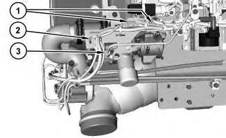
Illustration 1 g02161617
View of theAir Control Valve which is locatedon the Clean Emissions Module.
-29/05/2014 i05295284
1. Remove cable straps (2). Disconnect harness assemblies (1) and position the harnessassembly out of the way.
2. Remove tube assembly (3).
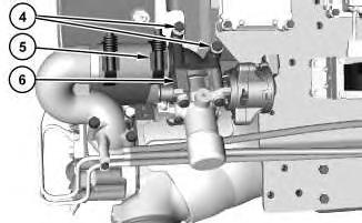
Illustration 2
g02161618
3. Loosen clamp assembly (5). Remove bolts (4) and remove air control valve (6).
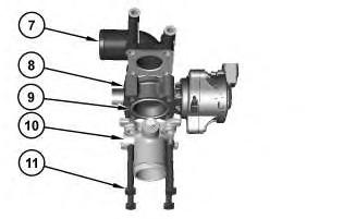
Illustration 3
g02161693
4. Remove bolts (11). Separate housings (10) and (7) from the air control valve actuator (8). Remove both seals (9) from the housings.
Installation Procedure
1. Install air control valve (8) in the reverse order of removal. Copyright 1993 - 2020 Caterpillar Inc. All Rights Reserved. Private Network For SIS Licensees.
Product: EXCAVATOR
Model: 336E LH EXCAVATOR RZA
Configuration: 336E LH & 336E LNH (Hybrid) Excavators RZA00001-UP (MACHINE) POWERED BY C9.3 Engine
Disassembly and Assembly C9.3
Engines for Caterpillar Built Machines
Media Number -KENR8149-07
Atmospheric Pressure Sensor - Remove and Install
SMCS - 1923-010
Removal Procedure
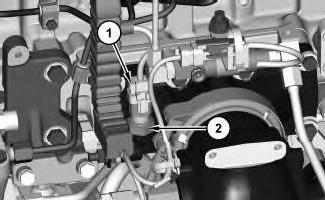
Illustration 1 g02142868
The pressure sensor is locatednear the engine inlet manifold.
1. Disconnect the harness assembly (1) and remove atmospheric pressure sensor (2).
Installation Procedure
Note: Do not pre-tighten the sensor using the plastic portion of the sensor. Pre-tighten the sensor using the metal hex portion of the sensor. Damage can occur to the sensor if pretightened using the plastic portion of the sensor.
1. Install pressure sensor (1) in reverse order of removal.
a. Tighten sensor (1) to a torque of 10 ±2 N·m (89 ± 18 lb in).
Copyright 1993 - 2020 Caterpillar Inc. All Rights Reserved. Private Network For SIS Licensees.
Mon Oct 12 10:09:52 UTC+0530 2020
Product: EXCAVATOR
Model: 336E LH EXCAVATOR RZA
Configuration: 336E LH & 336E LNH (Hybrid) Excavators RZA00001-UP (MACHINE) POWERED BY C9.3 Engine
Disassembly and Assembly C9.3
Engines for Caterpillar Built Machines Media
Bearing Clearance - Check
SMCS - 1203-535; 1219-535
Measurement Procedure
Table 1
Required Tools
Plastic Gauge (Green)
to 0.076 mm (0.001 to 0.003 inch)
Plastic Gauge (Red)
to 0.152 mm (0.002 to 0.006 inch)
Plastic Gauge (Blue)
to 0.229 mm (0.004 to 0.009 inch)
Plastic Gauge (Yellow)
0.230 to 0.510 mm (0.009 to 0.020 inch)
Note: Plastic gauge may not be necessary when the engine is in the chassis.
i05977048
Keep all parts clean from contaminants.
Contaminants may cause rapid wear and shortened component life.
Note: Cat does not recommend the checking of the actual bearing clearancesparticularly on small engines. Thisisbecause of the possibility of obtaining inaccurate results and the possibility of damaging the bearing or the journal surfaces. Each Cat engine bearing is quality checked for specific wall thickness.
Note: The measurements should be within specifications and the correct bearings should be used. If the crankshaft journals and the bores for the block and the rods were measured during disassembly, no further checks are necessary. However, if the technician still wants to measure the bearing clearances, Tooling (A) is an acceptable method. Tooling (A) is less accurate on journalswith small diametersif clearancesare less than 0.10 mm (0.004 inch).
NOTICE
Lead wire, shim stock or a dial bore gauge can damage the bearing surfaces.
The technician must be very careful to use Tooling (A) correctly. The following points must be remembered:
• Ensure that the backs of the bearings and the bores are clean and dry.
• Ensure that the bearing locking tabs are properly seated in the tab grooves.
• The crankshaft must be free of oil at the contact pointsof Tooling (A).
1. Put a piece of Tooling (A) on the crown of the bearing that is in the cap.
Note: Do not allow Tooling (A) to extend over the edge of the bearing.
2. Use the correct torque-turn specifications in order to install the bearing cap. Do not use an impact wrench. Be careful not to dislodge the bearing when the cap isinstalled.
Note: Do not turn the crankshaft when Tooling (A) is installed.
3. Carefully remove the cap, but do not remove Tooling (A). Measure the width of Tooling (A) while Tooling (A) is in the bearing cap or on the crankshaft journal. Refer to Illustration 1.
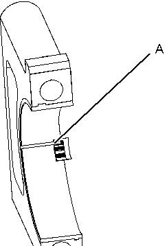

Illustration 1 g01152855
TypicalExample
4. Remove all of Tooling (A) before you install the bearing cap.
Note: When Tooling (A) is used, the readings can sometimes be unclear. For example, all parts of Tooling (A) are not the same width. Measure the major width in order to ensure that the parts are within the specification range. Refer to SpecificationsManual, "Connecting Rod Bearing Journal" and Specifications Manual, "Main Bearing Journal" for the correct clearances.
Copyright 1993 - 2020 Caterpillar Inc. All Rights Reserved. Private Network For SIS Licensees. Mon Oct 12 10:09:18 UTC+0530 2020
Product: EXCAVATOR
Model: 336E LH EXCAVATOR RZA
Configuration: 336E LH & 336E LNH (Hybrid) Excavators RZA00001-UP (MACHINE) POWERED BY C9.3 Engine
Disassembly and Assembly C9.3
Engines for Caterpillar Built Machines
Media Number -KENR8149-07
Belt Tensioner - Remove and Install
SMCS - 1358-010
Removal Procedure
1. Remove the drive belt. Refer to Operation and Maintenance Manual, "Belt - Replace".
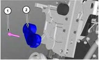
Illustration 1
g06060776
2. Remove bolt (1) and remove belt tensioner (2).
Installation Procedure
i06653775
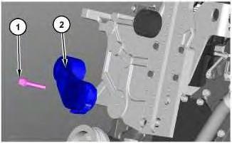
Illustration 2 g06060776
1. Position belt tensioner (2) and install bolt (1).
2. Install the drive belt. Refer to Operation and Maintenance Manual, "Belt - Replace".
Copyright 1993 - 2020 Caterpillar Inc. All Rights Reserved. Private Network For SIS Licensees. Mon Oct 12 10:15:36 UTC+0530 2020

Product: EXCAVATOR
Model: 336E LH EXCAVATOR RZA
Configuration: 336E LH & 336E LNH (Hybrid) Excavators RZA00001-UP (MACHINE) POWERED BY C9.3 Engine
Disassembly and Assembly C9.3
Engines for Caterpillar Built Machines
Media Number -KENR8149-07
Camshaft - Install
SMCS -1210-012
Installation Procedure Table 1 Required Tools
Keep all parts clean from contaminants.
Contaminants may cause rapid wear and shortened component life.
i05278252
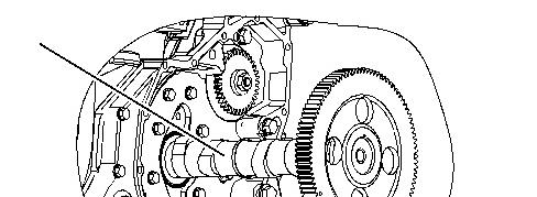
1 g03356215
NOTICE
Do not damage the lobes or the bearings when the camshaft is removed or installed.
Note: During the installation of the camshaft, rotate the camshaft in both directions in order to prevent binding in the camshaft bearing bores.
1. Lubricate the camshaft lobes and the valvelifter bore with a 50/50 mixture of Tooling (B). Apply clean engine oil on the camshaft bearing journals. Carefully install camshaft (10) in the cylinder block.

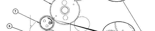
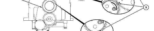
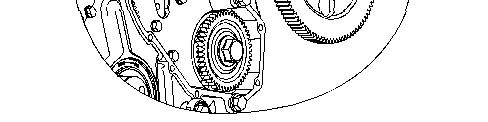
Illustration 2
(5) Gear for the high-pressure fuel pump
(6) Camshaft gear
(7) Idler gear
(8) Crankshaft gear
(9) Timing marks
g03356207
NOTICE
When installing the camshaft, make sure the number one cylinderis at top center of the compression stroke with the timing bolt installed in the flywheel.The camshaft timing is very important. The timing mark on the camshaft drive gear must line up with the timing mark on the idler gear. Refer to the Specifications Manual for more information.
2. Correct fuel injection timing and correct valve mechanism operation is determined by properly timing crankshaft gear (8) and camshaft gear (6) to idler gear (7). Also,high-pressure fuel pump gear (5) must betimed to camshaft gear (6).During installation of the front gear, timing marks (9) on idler gear (7) must be in alignment with the timing marks on crankshaft gear (8) and the timing marks on camshaft gear (6). The "0" mark on camshaft gear (6) must align with the timing mark on idler gear (7). The "V" mark on camshaft gear (6) must align with the "V" mark on fuel pump gear (5).