


This is the sample of the manual click on the download link for complete manual
For some reason if link does not work download this pdf and then click

Product: EXCAVATOR
Model: 336 EXCAVATOR DKS
Configuration: 336 Excavator DKS00001-UP (MACHINE) POWERED BY C9.3B Engine
Disassembly and Assembly
336, 336 GC and 340 Excavator Machine Systems
Media Number -M0087649-06 Publication Date -01/05/2020
Accumulator - Remove and Install
SMCS - 4263-010; 4331-010; 5077-010; 7336-010
i07356471
Reference: Special Instruction, "Visual Service Procedures - Colors and Symbols" , M0066576
Removal Procedure
Personal injury can result from hydraulic oil pressure and hot oil.
Hydraulic oil pressure can remain in the hydraulic system after the engine has been stopped. Serious injury can be caused if this pressure is not released before any service is done on the hydraulic system.
Make sure all of the work tools have been lowered to the ground, and the oil is cool before removing any components or lines. Remove the oil filler cap only when the engine is stopped, and the filler cap is cool enough to touch with your bare hand.
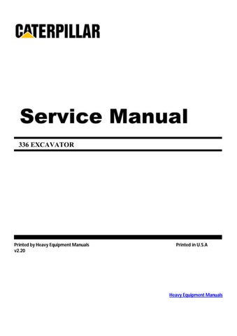
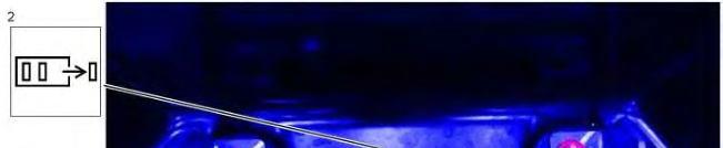
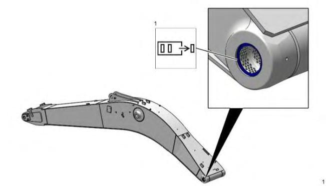
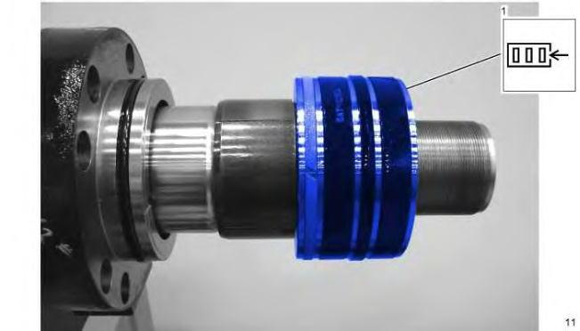
1
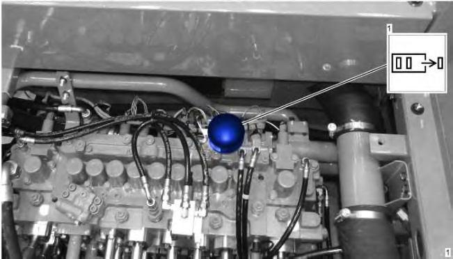
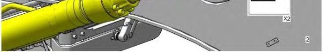
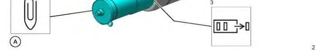
Illustration 2 g06292914
Inspect and replace the O-ring seal if needed.
Installation Procedure
1. Install the accumulator in the reverse order of removal.
Product: EXCAVATOR
Model: 336 EXCAVATOR DKS
Configuration: 336 Excavator DKS00001-UP (MACHINE) POWERED BY C9.3B Engine
Disassembly and Assembly
336, 336 GC and 340 Excavator Machine Systems
Media Number -M0087649-06 Publication Date -01/05/2020
Antenna (GPS) - Remove and Install
SMCS - 733B-010
Removal Procedure
-22/05/2020
i07395152
Reference: Special Instruction, "Visual Service Procedures - Colors and Symbols" M0066576.

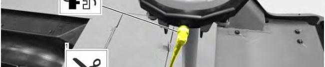

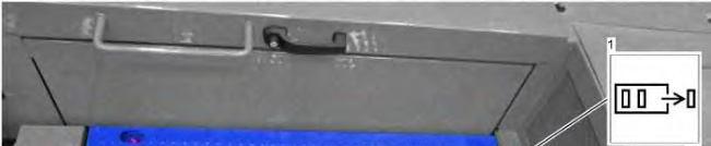
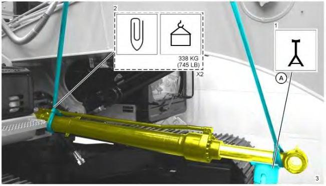
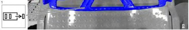
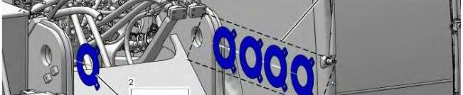
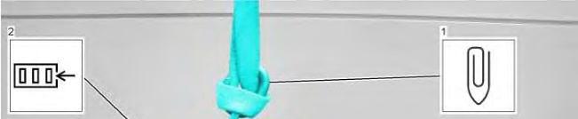
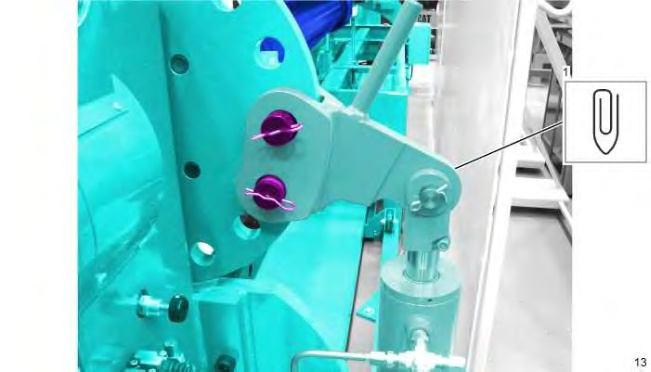
Illustration 1 g06307471
Repeat for the opposite side.
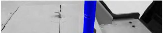
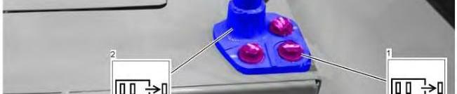
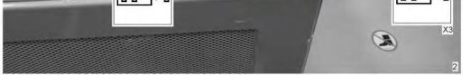
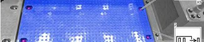
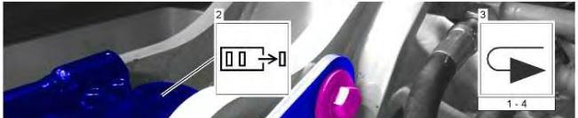
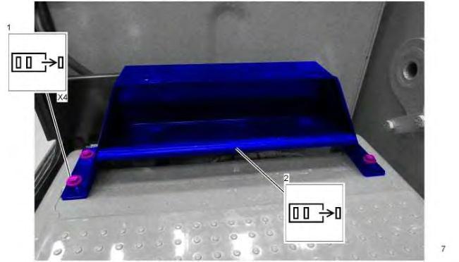
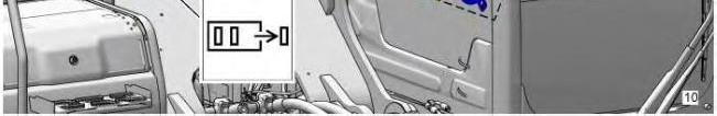
Illustration 2 g06307477
Repeat for the opposite side.
Installation Procedure
1. Install the GPS Antenna in the reverse order of removal.
Copyright 1993 - 2025 Caterpillar Inc. All Rights Reserved. Private Network For SIS Licensees.
Wed Feb 26 22:28:59 UTC+0700 2025
Product: EXCAVATOR
Model: 336 EXCAVATOR DKS
Configuration: 336 Excavator DKS00001-UP (MACHINE)
Disassembly and Assembly 336, 336 GC and 340 Excavator Machine Systems Media
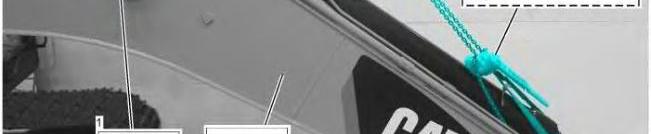
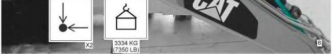
Boom - Remove and Install
SMCS - 6501-010
Removal Procedure Table 1
i07373341
Reference: Special Instruction,
Start By:
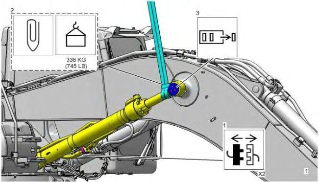
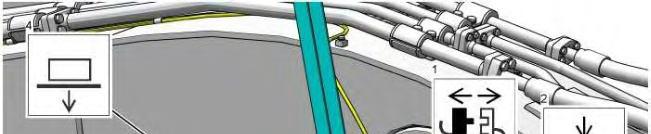
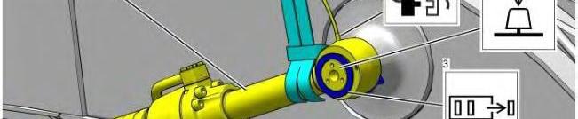
When you are using hydraulic cylinders and puller studs, always ensure that the rated capacity of the puller stud meets or exceeds the rated capacity of the hydraulic cylinder. If the puller stud does not meet or exceed the rated capacity of the hydraulic cylinder, a sudden failure of the puller stud could occur. The sudden failure of the puller stud could result in personal injury or death.
1. Lower the boom to the ground. Release the system hydraulic pressure.
2. Drain the hydraulic fluid. Refer to , M0082496, "Operation and Maintenance Manual" , Hydraulic System Oil - Change for the draining and refilling procedures.


Installation Procedure
1. Install boom in the reverse order of removal.
Copyright 1993 - 2025 Caterpillar Inc. All Rights Reserved. Private Network For SIS Licensees.
Wed Feb 26 22:29:56 UTC+0700 2025
Product: EXCAVATOR
Model: 336 EXCAVATOR DKS
Configuration: 336 Excavator DKS00001-UP (MACHINE) POWERED BY C9.3B Engine
Disassembly and Assembly
336, 336 GC and 340 Excavator Machine Systems
Boom Bearings and Seals - Remove and Install
SMCS - 6501-010-BD; 6501-010-SA
Removal Procedure
Reference: Special Instruction, "Visual Service Procedures - Colors and Symbols" , M0066576 Table 1 Required Tools
Start By:
a. Remove the
exceed the rated capacity of the hydraulic cylinder, a sudden failure of the puller stud could occur. The sudden failure of the puller stud could result in personal injury or death.


Repeat steps 1 and 2 for opposite side.
Installation Procedure
2
B 1P-0520 Driver Gp 1
C 5P-0960 Molybdenum Grease 1
Note: Make sure that the bores for the sleeve bearings are free of paint and grease prior to the installation of the sleeve bearings.
Note: Make sure that the bearings are installed in the bore so that the identification numbers of the bearings are facing outward.
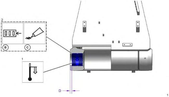
Illustration 3
Use Tooling (B) to drive the sleeve bearing into the bearing bore to the depth of dimension (D) 9.5 ± 0.8 mm (0.37 ± 0.03 inch).
g06201500


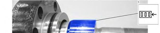
Illustration 4 g06201501
Repeat steps 1 and 2 for opposite side.
End By:
a. Install the boom.
Copyright 1993 - 2025 Caterpillar Inc. All Rights Reserved. Private Network For SIS Licensees.
Wed Feb 26 22:30:54 UTC+0700 2025
Product: EXCAVATOR
Model: 336 EXCAVATOR DKS
Configuration: 336 Excavator DKS00001-UP (MACHINE) POWERED BY C9.3B Engine
Disassembly and Assembly
336, 336 GC and 340 Excavator Machine Systems
Media Number -M0087649-06
Boom Cylinder - Assemble
SMCS - 5456-016
i07311316
Reference: Special Instruction, "Visual Service Procedures - Colors and Symbols" M0066576
Assemble Procedure
Table 1
Required Tooling Tool Part Number
Description
A 152-4251 Hydraulic Repair Bench 1 B - Loctite 648 Retaining Compound -
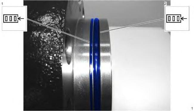
Illustration 1
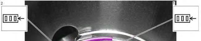


Illustration 2
Lubricate the cup seal and the buffer seal with the fluid that is being sealed.
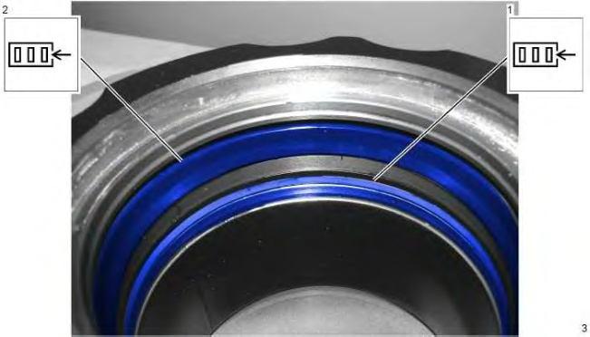
Illustration 3
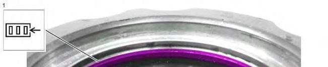


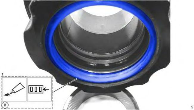
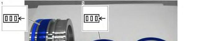

Illustration 6 g06279837
Lubricate ID and OD of the rings and the seal assembly with clean hydraulic oil.


Illustration 7 g06279843
Lubricate ID and OD of the ring with clean hydraulic oil.


8 g06279844
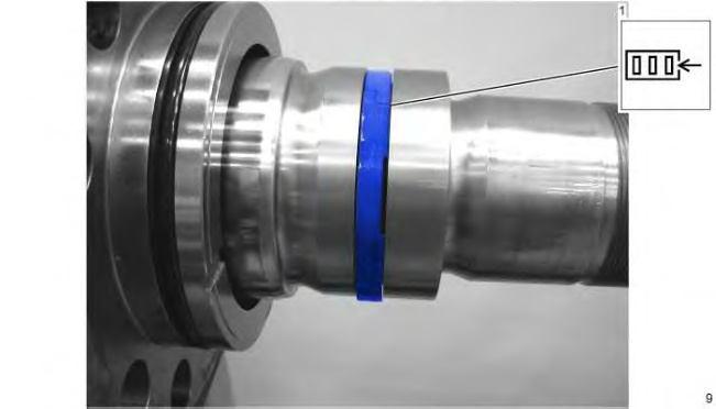
Illustration 9 g06279845
The seal must be installed in the same orientation that the seal was in the disassembly procedure. The slit of the seal must turn in direction of the piston.


This is the sample of the manual click on the download link for complete manual
For some reason if link does not work download this pdf and then click