Removal Procedure of the Actuator Motor for the Front Air Damper
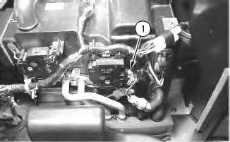
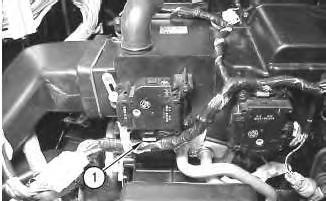
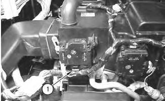
1. Disconnect harness assembly (1) from the actuator motor.
6
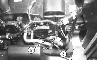
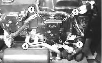
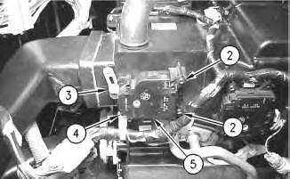
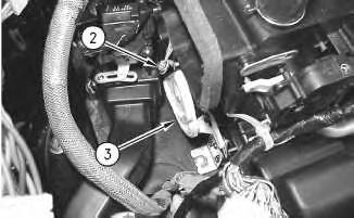
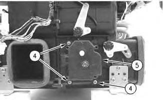
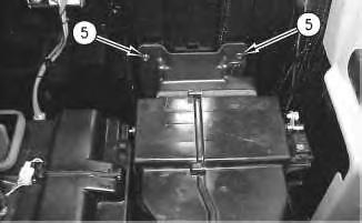
2. Remove screw (4). Remove the cable strap for the harness assembly.
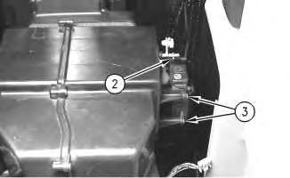
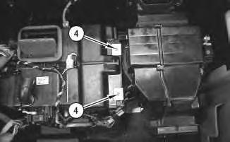
3. Remove screws (2) from the actuator motor.
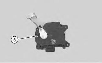
4. Remove actuator motor (5).
Illustration 5
g00699809
Illustration
g00699811
Illustration 7
g00699816
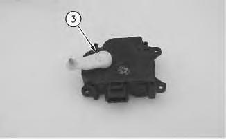
5. Remove linkage (3) from the actuator motor.
Removal Procedure of the Actuator Motor for the Fresh Air or Recirculated Air Damper
8
g00699825
1. Disconnect harness assembly (1) from the actuator motor.
9
2. Remove screw (2) from the linkage.
Illustration
Illustration
g00699828
Illustration 10
g00699833
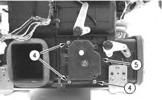
The heating and air conditioning unit is removed for photographic purposes.
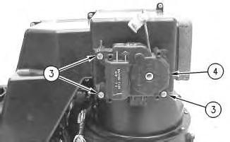
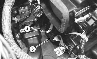
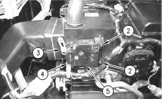
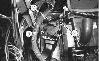
3. Remove screws (3) from the actuator motor.
4. Remove actuator motor (4).
Illustration 11
g00699850
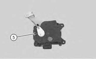
5. Remove linkage (5) from the actuator motor.
Removal Procedure of the Actuator Motor for the Air Damper for the Rear Window Defroster
Illustration 12
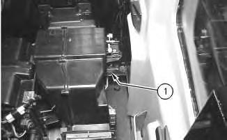
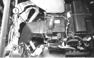
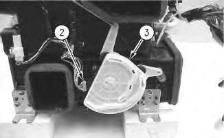
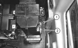
1. Remove air duct (1).
13
Illustration 14 g00699876
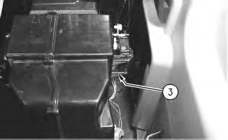
The heating and air conditioning unit is removed for photographic purposes.
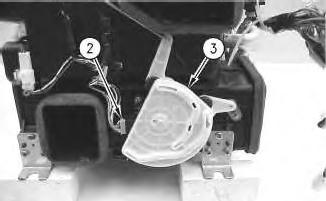
2. Disconnect harness assembly (2) from the actuator motor.
3. Remove cam (3) from the actuator motor.
15
Illustration
g00700177
Illustration
g00700179
Illustration 16
g00699881
The heating and air conditioning unit is removed for photographic purposes.
4. Remove screws (4).
5. Remove actuator motor (5).
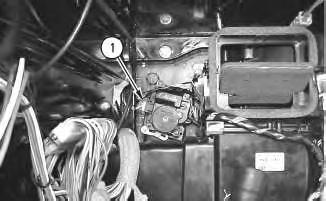
Removal Procedure of the Actuator Motor for the Air Damper for the Front Window
17
1. Disconnect harness assembly (1) from the actuator motor.
Illustration
g00699893
Illustration 18
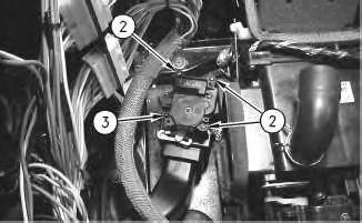
2. Remove screws (2).
3. Remove actuator motor (3).
Illustration 19
g00699909
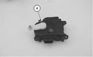
4. Remove linkage (4) from the actuator motor.
Installation Procedure
Installation Procedure of the Actuator Motor for the Air Damper for the Temperature Control
g00699902
20
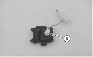
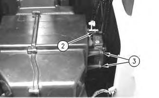
1. Install linkage (6) on the actuator motor.
21
2. Install actuator motor (5) on the heating and air conditioning unit.
3. Install screws (4) in the actuator motor.
Illustration 22
Note: Make sure that the linkage is properly aligned in the air actuator.
4. Connect linkage (3). Install screw (2).
Illustration
g00699790
Illustration
g00699782
g00699776
23
5. Connect harness assembly (1) to the actuator motor.
Installation Procedure of the Actuator Motor for the Front Air Damper
Illustration 24
1. Install linkage (3) on the actuator motor.
25
Illustration
g00699772
g00699816
Illustration
g00699811
Note: Make sure that linkage (3) is properly aligned with the air actuator.
2. Install actuator motor (5).
3. Install screws (2) in the actuator motor.
4. Install a new cable strap for the harness assembly. Install screw (4).
26
5. Connect harness assembly (1) to the actuator motor.
Installation Procedure of the Actuator Motor for the Fresh Air or Recirculated Air Damper
27
1. Install linkage (5) on the actuator motor.
Illustration
g00699809
Illustration
g00699850
Illustration 28
g00699833
The heating and air conditioning unit is removed for photographic purposes.
2. Install actuator motor (4).
3. Install screws (3) in the actuator motor.
Illustration 29
4. Connect the linkage to the air actuator.
5. Install screw (2) in the linkage.
g00699828
30
Illustration
g00699825
6. Connect harness assembly (1) to the actuator motor.
Installation Procedure of the Actuator Motor for the Air Damper for the Rear Window Defroster
Illustration 31
g00699881
The heating and air conditioning unit is removed for photographic purposes.
1. Install actuator motor (5).
2. Install screws (4).
Illustration 32
g00699876
The heating and air conditioning unit is removed for photographic purposes.
Note: Make sure that the linkages for the air dampers are installed in the cam.
3. Install cam (3) on the actuator motor.
4. Connect harness assembly (2) to the actuator motor.
Illustration 33
5. Install air duct (1).
Installation Procedure of the Actuator Motor for the Air Damper for the Front Window
Illustration 34
1. Install linkage (4) on the actuator motor.
35
g00699868
g00699909
Illustration
g00699902
2. Install actuator motor (3).
3. Install screws (2).
36
4. Connect harness assembly (1) to the actuator motor.
End By:
a. Install the storage box in the cab. Refer to Disassembly and Assembly, "Storage Box and Covers (Cab) - Remove and Install". Copyright 1993 - 2024 Caterpillar Inc. All Rights Reserved. Private Network For SIS Licensees. Tue Jun 18 23:44:15 UTC+0530 2024
Illustration
Product: EXCAVATOR
Model: 330C L EXCAVATOR CAP
Configuration: 330C L & 330C LN Excavators CAP00001-UP (MACHINE) POWERED BY C-9 Engine
Disassembly and Assembly
330C Excavator Machine Systems
Media Number -RENR5438-15
i02346921
Blower Motor (Air Conditioner, Heater) - Remove and Install
SMCS - 7304-010-BW; 7309-010-BW; 7320-010-BW
Removal Procedure
Start By:
A. Remove the storage box in the cab. Refer to Disassembly and Assembly, "Storage Box and Covers (Cab) - Remove and Install".
Illustration 1 g00698935
1. Disconnect harness assembly (1) from the temperature sensor.
2. Disconnect harness assembly (2) from the relays.
Illustration 2
g00698960
3. Disconnect harness assembly (3) from the damper motor.
Illustration 3
4. Remove screws (4) and the brackets.
g00698971
Illustration 4
5. Remove screws (5) from the air duct.
g00698972
Illustration 5
g00698974
Illustration 6 g00698986
Illustration 7 g00699002
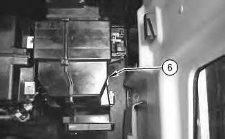
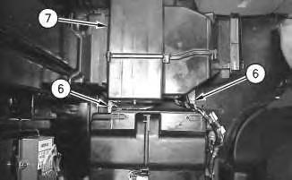
6. Remove bolts (6) that secure blower motor housing (7) to the platform.
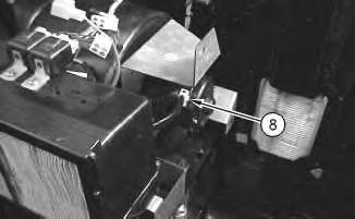
7. Carefully lift blower motor housing (7) in order to disconnect harness assembly (8) from the blower motor.
8
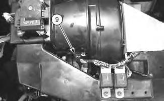
8. Disconnect clip (9) from the blower motor housing and remove the blower motor housing from the machine.
9
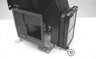
9. Remove screw (10) from the support.
Illustration
g00699006
Illustration
g00699502
Illustration 10
g00699125
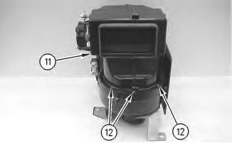
10. Remove screws (12) and air duct (11) from the blower motor.
Illustration 11
g00699159
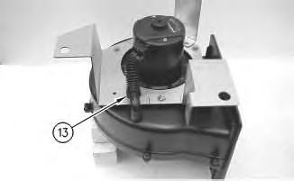
11. Remove hose assembly (13) from the blower motor.
Illustration 12
g00699149
Illustration 13 g00699163
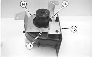
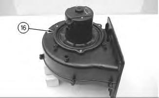
12. Remove bolts (14) and support (15) from blower motor (16) . Remove blower motor (16) from the housing.
Illustration 14
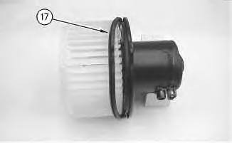
13. Remove seal (17) from the blower motor.
g00699166
Illustration 15
g00699168
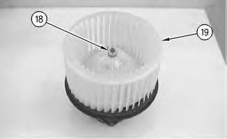
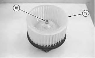
14. Remove retaining clip (18) and blower wheel (19) .
Installation Procedure
16
1. Install blower wheel (19) and retaining clip (18) .
Illustration 17
2. Install seal (17) on the blower motor.
Illustration 18
g00699163
Note: Make sure that blower motor (16) is properly aligned in the housing.
Illustration
g00699168
g00699166
This is the sample of the manual click on the download link for complete manual
DOWNLOAD LINK
For some reason if link does not work download this pdf and then click