CAT Caterpillar 3306C Service Repair Manual PDF Download
Note: Use Bookmarks panel to navigate
Product: TRUCK ENGINE
Model: 3306C TRUCK ENGINE 7RJ
Configuration: 3306C Truck Engine 7RJ00001-UP
Disassembly and Assembly
3306C DIESEL TRUCK ENGINE Media
-01/01/1992
Fuel Injection Pump Housing And Governor
SMCS - 1286-011; 1286-012
Remove Fuel Injection Pump Housing And Governor
Start By:
a. remove fuel injection lines
NOTICE
Keep all parts clean from contaminants. Contaminants put into the system may cause rapid wear and shortened component life.
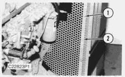
1. Remove bolts (1) and fan guard (2).
-11/10/2001
This is the sample of the manual click on the download link for complete manual
DOWNLOAD LINK
For some reason if link does not work download this pdf and then click
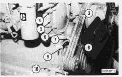
2. Loosen bolts (7), (9) and (10). Remove belts (8).
3. Remove bolt (4) to clip. Remove grease line (3).
4. Remove nuts (6). Remove cover (5) and the gasket.
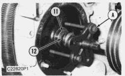
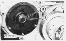
5. Loosen bolt (12) enough to leave a gap of 3.18 mm (.125 in) between washers (11) and the fuel pump drive gear.
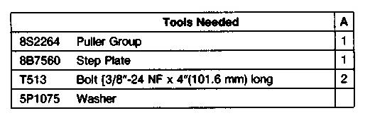
6. Install tool (A) as shown. Tighten the stud to pull the fuel pump drive gear loose from the taper on the fuel injection pump camshaft.
7. Remove tool (A), bolt (12), and washer (11).
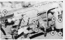
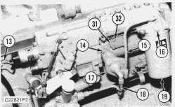
8. Identify and disconnect wires (13).
9. Remove tube assemblies (15) and (18).
10. Remove two bolts (14), fuel transfer pump (17), and the O-ring seal.
11. Remove bolts (16), the filter base, the gasket, and filter (19).
12. Fasten the fuel injection pump housing and governor to a hoist.
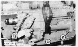
13. Remove two bolts (22), three nuts (21), and the fuel injection pump housing and governor. The weight of the fuel injection pump housing and governor is 29 kg (64 lb.).
14. Remove the two O-ring seals from the bottom of the fuel injection pump housing and governor.
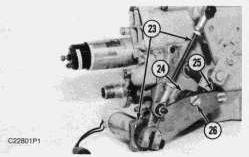
15. Loosen screw (25). Remove two screws (26), control assembly (23) and spacers (24).
Install Fuel Injection Pump Housing And Governor
Start By:
a. remove fuel injection lines
b. remove valve cover
NOTE: Number 1 piston must be set at top dead center (TDC) to perform all timing procedures.
NOTE: The engine is seen from the flywheel end when direction of crankshaft rotation is given.
1. Remove the starter.
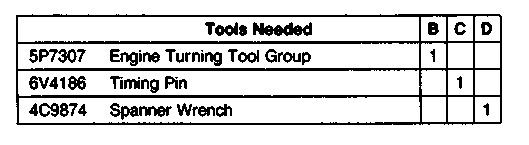
2. Install tool (B) on flywheel housing as shown.
3. To find TDC for No. 1 piston;
a. Turn the flywheel clockwise (opposite the direction of engine rotation) approximately 30 degrees. This removes all play from the timing gears.
NOTE: If you go past the bolt hole, you must repeat Step (a).
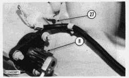
b. Turn the flywheel counterclockwise until a 3/8" - 16 x 2 1/4" NC bolt (27) can be installed in the flywheel through the hole in the flywheel housing. The No. 1 and No. 6 pistons are now at top center position.
NOTE: The No. 1 piston is on the compression stroke when the valves of the No. 1 cylinder are closed. The rocker must be free to move up and down.
4. If No. 1 piston is not on the compression stroke, remove the 3/8" - 16 x 2 1/4" NC bolt (27) and turn the flywheel 360° counterclockwise. Install the 3/8" bolt as before. The No. 1 piston is now at TDC.
Typical Example
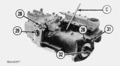
5. Install tooling (C) in the fuel injection pump housing as shown. Push on tooling (C) and turn injection pump camshaft (32). When tooling (C) engages the groove (slot) in the camshaft, the fuel injection pump is in the No. 1 piston TDC position.
6. Be sure O-ring seals (28), (29), (30) and (31) are in position on the fuel injection pump housing and governor. Put clean engine oil on the seals.
7. Place control assembly (23) and spacers (24) in position on the fuel injection pump housing and governor. Install screws (26) and tighten screw (25).
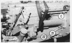
8. Attach a hoist and put the fuel injection pump housing and governor in position on the timing gear plate and oil manifold. Install three nuts (21) and two bolts (22).
9. Put the drive gear in position on the fuel injection pump and install washers (11) and bolt (12) finger tight. Be sure that tool (C) is in the notch in the camshaft of the fuel injection pump.
10. Install a 3/8" - 24 x 1/2" NC bolt in one of the holes in the drive gear.
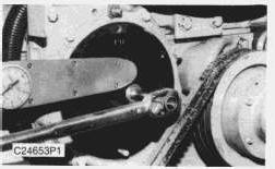
11. Install tool (D) to hold the gear. Use a torque wrench to place a force of 68 N·m (50 lb ft) on the 3/8" bolt. Tighten the drive gear bolt to a torque of 270 ± 25 N·m (200 ± 18 lb ft). Remove tool (C) from the fuel pump and the 3/8" - 16 x 2 1/4" bolt (27) from the flywheel.
12. With tooling (B), turn the engine flywheel two complete revolutions. When the 3/8" - 16 x 2 1/4" bolt goes in the hole in the flywheel when the timing pin is installed in the notch in the camshaft, the timing is correct.
13. Remove tool (B).
14. Put cover (31) and the gasket in position. Install four bolts (32).
15. Put the filter base, the gasket, and filter (19) in position. Install bolts (16).
16. Put fuel transfer pump (17) and the O-ring seal in position. Install two bolts (14).
17. Install tube assemblies (18) and (15). Connect wires (13).
18. Put the gasket and cover (5) in position. Install the washers and nuts (6). Install grease line (3) and bolt (4) to the clip.
19. Install belts (8). Use belt tension gauge and adjust the fan belts. Measure the bell farthest from the engine. Tighten new belts until gauge indication is 534 ± 22 N (120 ± 5 lb.). Tighten bolt (7), bolt (9), and bolt (10). Operate the engine at high idle for a minimum of 30 minutes after Step 18. Make another adjustment of the belt tension. The correct gauge indication for a used belt is 400 ± 44 N (90 ± 10 lb.). Tighten bolt (7), bolt (9), and (10).
20. Put fan guard (2) in position and install bolts (1).
End By:
a. install valve cover
b. install fuel injection lines
Thu Apr 11 00:44:02 UTC+0530 2024
Product: TRUCK ENGINE
Model: 3306C TRUCK ENGINE 7RJ
Configuration: 3306C Truck Engine 7RJ00001-UP
General Service Information
3306C DIESEL TRUCK ENGINE
Media Number -SEBR0552-00
General Instructions (D & A)
-01/01/1992
-11/10/2001
The following instructions will prove helpful to disassemble and assembly engine components. The information should be read and then referred to as necessary.
Cleanliness
Whenever hydraulic, fuel, lubricating oil or air lines are disconnected, clean the point of disconnection and the adjacent area. As soon as the disconnection is made, cap, plug or tape the line or opening to prevent entry of foreign material. The same recommendations for cleaning and covering apply when access covers or inspection plates are removed.
Clean and inspect all parts. Be sure all passages and holes are open. Cover all parts to keep them clean. Be sure parts are clean when installed. Leave new parts in their containers until ready for assembly.
Removal And Installation
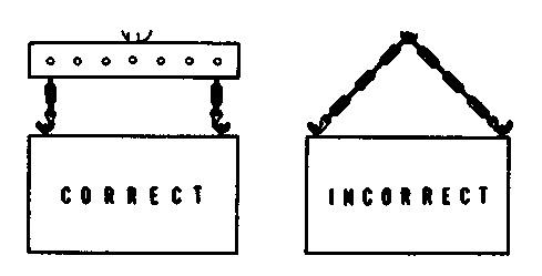
Unless otherwise specified, all removals should be accomplished using an adjustable lifting beam. All supporting Members (chains and cables) should be parallel to each other and as near perpendicular as possible to the top of the object being lifted.
When it is necessary to remove a component on an angle, remember that the capacity of an eyebolt diminishes as the angle between the supporting members and the object becomes less than
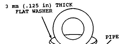
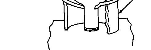
90°. Eyebolts and brackets should never be bent and should only have stress in tension. A length of pipe and a washer can be used, as shown, to help relieve these stresses on eyebolts.
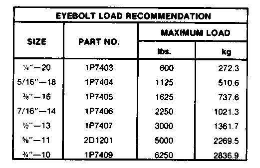
Forged eyebolts are available. Each eyebolt has a maximum load recommendation.
Some removals require the use of lifting fixtures to obtain proper balance and to provide safe handling.
If a part resists removal, check to be certain all nuts and bolts have been removed and that an adjacent part is not interfering.
Disassembly And Assembly
When assembling an engine, complete each step in turn. Do not partially assemble one part and start assembling some other part. Make all adjustments as recommended. Always check the job after it is completed to see that nothing has been overlooked.
Lubrication For A Rebuilt Engine
It is very important for a rebuilt engine to have "adequate" (needed) lubrication during the first seconds of operation. A "dry start" (without needed lubrication) on a rebuilt engine or an engine that has been in storage can cause bearing damage.
To prevent the possibility of a "dry start" and bearing damage during the first few seconds of running, use the 1P0540 Flow Checking Tool Group and shop air pressure to pressure lubricate (fill the main oil passage with oil under pressure) all rebuilt engines and all engines that have been in storage.
Procedure For Pressure Lubrication
1. Clean the tank of the 1P0540 Flow Checking Tool Group thoroughly, and set the pressure regulator to 240 ± 35 kPa (35 ± 5 psi).
Air pressure should not be more than 345 kPa (50 psi) at any time.
2. Put the correct engine oil into the tank. Use a minimum of 30% of the engine oil capacity. For some engines it will be necessary to fill the tank several times to get the correct amount of oil in the engine.
3. Connect the tooling to the main oil passage of the engine.
4. Add air pressure to the tank, with the regulator set at 240 ± 35 kPa (35 ± 5 psi). Although the tank has a hand pump, it is difficult to get enough air pressure to do the job with the hand pump. Therefore, use of shop air is recommended.
5. Let the engine oil flow into the oil passage under pressure.
Fill the crankcase with the correct engine oil. The amount of oil used in the pressure lubrication procedure must be subtracted from the recommended refill capacity in the Operation Maintenance Manual. If the engine is not going to be used for a long time, do the above procedure again before the first start.
If shop air is not available, for charging the tank, the hand pump may be used to get the minimum required pressure.
DO NOT use the same 1P0540 Flow Checking Tool Group for both "pressure lubrication application" and for checking fuel flow. Incorrect cleaning is probable if the tool is used for both fuel and lubrication oil. Even a minute amount of dirt in the fuel system can cause fuel nozzle failure.
Initial Operation After Engine Reconditioning
The quality of oil control components used in Caterpillar engines is such that, following engine reconditioning (with Caterpillar Service Parts), only an initial operational check is necessary before continued operation in normal service.
The purpose of this initial operational check is to: insure that the engine has been assembled properly; determine if proper pressures and temperatures are maintained in the lubrication, cooling, and fuel systems; correct any leaks; perform necessary adjustments (such as valve clearance, governor high and low idle speeds, etc.); check the set point.
To provide a safe, uniform initial operational check, the following procedure is recommended:
1. Motor engine at cranking speed until oil pressure is observed.
2. Operate engine for 10 minutes at low idle.
3. Operate engine for 15 minutes at half-load and 3/4rated engine speed.
4. Operate engine for 30 minutes at rated load and speed.
Service Tools
Puller Assembly (2 Or 3 Arm)
Two or three arm pullers assemblies can be used to remove gears, bearing cages, hubs, bearings, shafts, etc.
Push Pullers
Push Pullers can be used to remove pulleys, gears, shafts, etc., and can be used in a variety of pulling combinations.
Bearing Pulling Attachment
Bearing Pulling Attachments can be used with forcing bolts, to remove shafts, bearings, gears, etc. They can be used with Push Pullers to provide a variety of pulling combinations.
Bearing Cup Pulling Attachment
Bearing Cup Pulling Attachments are used to remove bearing races or cups, sleeve-type bearings, bearings, seats, etc. and can be used with Push Pullers.
Rules For Use Of Tools
Rule 1: Always use safe Tools.
Rule 2: Keep tools in safe working condition.
Rule 3: Use the correct tool for the job.
Rule 4: Common sense with tools pays off.
Pressing Parts
When pressing one part into another, use 5P3931 Anti-Seize Compound or a molybdenum disulfide base compound to lubricate the mating surfaces.
Assemble tapered parts dry. Before assembling parts with tapered splines, be sure the splines are clean, dry and free from burrs. Position the parts together by hand to mesh the splines before applying pressure.
If parts which are fitted together with tapered splines are not tight, inspect the tapered splines and discard if worn.
Bolts And Bolt Torque
A bolt which is too long may "bottom" before the head is tight against the part it is to hold. The threads can be damaged when a "long" bolt is removed.
If a bolt is too short, there may not be enough threads engaged to hold the part securely.
Apply proper torque values to all bolts and nuts when assembling Caterpillar Equipment. When a specific torque value is required, the value is listed in the Specifications Section of this Service Manual. Tighten all other bolts and nuts for general usage, hydraulic valve bodies, or taperlock studs to the torque values given in the torque charts shown in this Service Manual.
NOTE: Take care to avoid mixing metric and inch fasteners. Mismatched or incorrect fasteners can result in mechanical damage or malfunction, or possible personal injury. Original fasteners removed during disassembly should be saved for assembly when possible. If new ones are required, caution must be taken to replace with one that is of same part number and grade.
Metric thread fasteners are identified by material strength (grade) numbers on bolt heads and nuts. Numbers on bolts will be 8.8, 10.9, etc. Numbers on nuts will be 8, 10, etc.
T-T-T Procedure
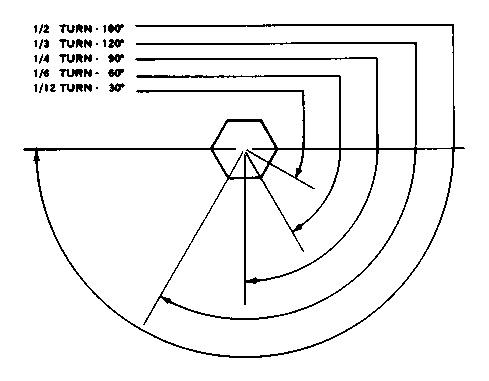
A torque-turn-tighten (T-T-T) procedure is used in many specifications and instructions.
1. Clean the bolt and nut threads.
2. Put lubrication of the threads and the seat face of the bolt and nut.
3. Turn the bolt or the nut tight according to the torque specification.
4. Put a location mark on the part and on the bolt head or nut.
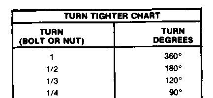
5. Turn the bolt or the nut tighter the amount of degrees according to the specifications
NOTE: The side of a nut or bolt head can be used for reference if a mark can not be put on.
Torque Wrench Extension
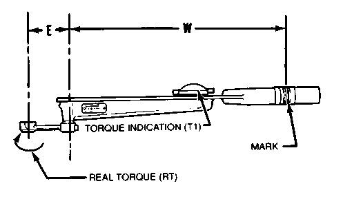
When a torque wrench extension is used with a torque wrench, the torque indication on the torque wrench will be less than the real torque.
(E) Torque wrench drive axis-to-torque wrench extension drive axis. (W) Mark on handle-to-torque wrench drive axis.
1. Put a mark on the handle. Measure the handle from the mark to the axis of the torque wrench drive (W).
2. Measure the torque wrench extension from the torque wrench drive to the axis of the torque wrench extension drive (E).
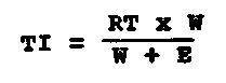
3. To get correct torque indication (TI) when the real torque (RT) is known:
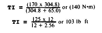
Example: W = 304.8 mm (12 in); E = 65.0 mm (2.56 in); RT (from specifications) = 17 N·m (125 lb ft).
4. Hold the torque wrench handle with the longest finger of the hand over the mark on the handle to get the real torque (RT) with low torque indication (TI) on the torque wrench.
Locks
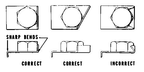
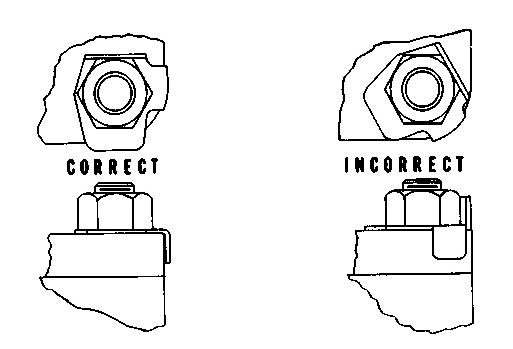
Flat metal locks must be installed properly to be effective. Bend one end of the lock around the edge of the part. Bend the other end against one flat surface of the nut of bolt head.
Always install new locks in components which house moving parts.
If lockwashers are installed on housings made of aluminum, use a flat washer between the lockwasher and the housing.
Lines And Wires
When removing or disconnecting a group of lines or wires, tag each one to assure proper assembly.
Lubrication
Where applicable, fill the compartments of the components serviced with the amount, type and grade of lubricant recommended in the Operation Maintenance Manual.
Rust Preventive Compound
Clean the rust preventive compound from all machined surfaces of new parts before installing the part.
Shims
When shims are removed, tie them together and identify them as to location. Keep shims clean and flat until they are reinstalled.
Bearings
Anti-Friction Bearings
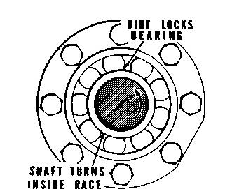
When an anti-friction bearing is removed, cover it to keep out dirt and abrasives. Wash the bearings in nonflammable cleaning solution and allow them to drain dry. The bearings may be dried with compressed air, but DO NOT SPIN THE BEARING.
Discard the bearings if the races and balls or rollers are pitted, scored or burned. If the bearing is serviceable, coat it with oil and wrap it in clean paper. DO NOT unwrap new bearings until time of installation.
The life of an anti-friction bearing will be shortened if not properly lubricated.
Double Row, Tapered Roller
Double row, tapered roller bearings are precision fit during manufacture and the components are not interchangeable. The cups, cones and spacers are usually etched with the same serial number and letter designator. If no letter designators are found, wire the components together to assure correct installation. Reusable bearing components should be installed in their original positions.
Heating Bearings
Bearings which require expansion for installation should be heated in oil not to exceed 121°C (250°F). When more than one part is heated to aid in assembly, they must be allowed to cool and then pressed together again. Parts often separate as they cool and shrink.
Installation
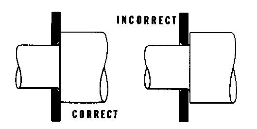
Lubricate new or used bearings before installation. Bearings that are to be preloaded must have a film of oil over the entire assembly to obtain accurate preloading. When installing a bearing, spacer or washer against a shoulder on a shaft, be sure the chamfered side is toward the shoulder.
When pressing bearings into a retainer or bore, apply pressure to the outer race. If the bearing is pressed on the shaft, apply pressure on the inner race.
Preload
Preload is an initial force placed on the bearing at the time of assembly.
Determine preload or end clearance form the Specifications Section of this Service Manual. Care should be exercised in applying preload. Misapplication of preload to bearings requiring end clearance can result in bearing failure.
Sleeve Bearings
DO NOT INSTALL SLEEVE BEARINGS WITH A HAMMER. Use a press, if possible and apply the pressure directly in line with the bore. If it is necessary to drive on a bearing, use a driver or a bar with a smooth flat end. If a sleeve bearing has an oil hole, align it with the oil hole in the mating part.
Gaskets
Be sure the holes in the gaskets correspond with the lubricant passages in the mating parts. If it is necessary to make gaskets, select stock of the proper type and thickness. Be sure to cut holes properly. Blank gaskets can cause serious damage.
Batteries
Clean batteries by scrubbing with a solution of baking soda and water. Rinse with clear water. After cleaning, dry thoroughly and coat terminals and connections with anti-corrosion compound or grease.
If an engine is not to be used for a long period of time, remove the batteries. Store them in a cool, dry place. A small charge should be introduced periodically to keep the specific gravity rating at the recommended level.
Seals (Lip-Type)
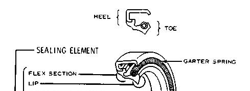
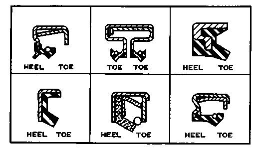
Generally the toe or spring-loaded lip of an oil seal faces the oil being sealed or the oil having the higher pressure. The toe or lip of a grease seal faces away from the lubricant being sealed. Unless otherwise specified, use the preceding rules for installing lip-type seals.
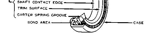
The main parts of a lip-type seal are the case, sealing element, and the garter spring. The illustration shows the construction of a simple lip-type seal. The cross section shows the terms "heel" and "toe" used to identify the sides of various types of seals.
Lubricate the lips of lip-type seals before installation. Use the same type of lubricant which the seal will be operating. Do Not use grease on any seal except a grease seal.
If during installation, the seal lip must pass over a shaft that has splines, a keyway, rough surface or a sharp edge, the lip can easily be damaged. Shim stock or other such material can be formed around the area to provide a smooth surface over which to slide the seal.
Seals (Hydrodynamic)
The hydrodynamic seal is different from the lip-type seal. The difference is the hydrodynamic grooves in the sealing lip of this seal. These grooves move lubrication oil back into the engine crankcase as the crankshaft turns. Because of this seal lip design, the front seal for an engine is different from the rear seal. The installed position of the seal lip is important because the seal grooves are sensitive to the direction of crankshaft rotation. Each seal is marked with an arrow to show the direction of engine rotation. If the seal is not installed correctly, oil in the crankcase will actually be removed. Special handling and installation procedures are given in Special Instruction, Form No. SMHS8508
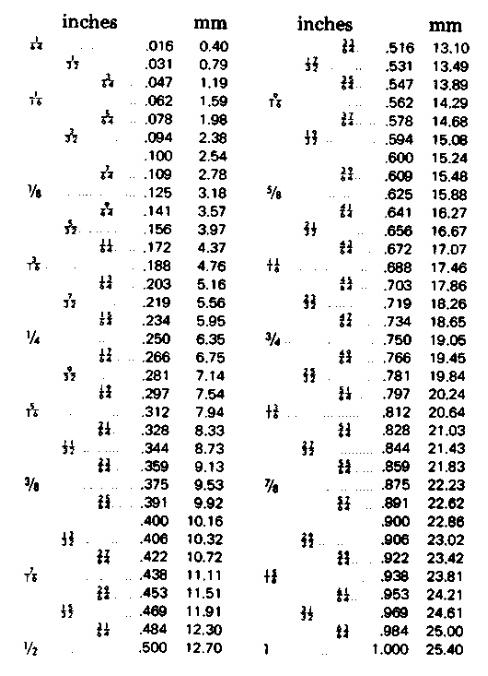
Conversion Chart (Inches To MM)
Copyright 1993 - 2024 Caterpillar Inc.
Rights Reserved.
Network For SIS Licensees. Thu Apr 11 00:35:24 UTC+0530 2024
Product: TRUCK ENGINE
Model: 3306C TRUCK ENGINE 7RJ
Configuration: 3306C Truck Engine 7RJ00001-UP
Disassembly and Assembly
3306C DIESEL TRUCK ENGINE
Media Number -SEBR0552-00
Measuring Main Bearing Clearances
SMCS - 1307-010
Using Plastigage to Measure Clearances
NOTE: Caterpillar does not recommend checking actual engine bearing clearances, particularly on small engines, because of the possibility of obtaining inaccurate results, and the possibility of damaging the bearing or journal surfaces. Each Caterpillar engine bearing is quality checked for specific wall thickness.
NOTE: If the crankshaft journals and bores for the block and rods were measured at disassembly and found to be within specifications, no further checks are necessary when using the correct bearings. However, if the serviceman still wants to measure the bearing clearances, Plastigage is an acceptable method. Plastigage is less accurate on small diameter journals where clearances are less than 0.10 mm (0.004 in).
NOTICE
Lead wire, shim stock or a dial bore gauge can damage the bearing surfaces.
1. The serviceman must be very careful to use Plastigage correctly, the following points must be remembered:
a. Make sure that the backs of the bearings and the bores are clean and dry.
b. Make sure that the bearing locking tabs are properly seated in their slots.
c. The crankshaft must be free of oil where the Plastigage touches it.
d. If the main bearing clearances are checked with the engine upright or on its side, the crankshaft must be supported. Use a jack under an adjacent crankshaft counterweight and hold the crankshaft against the crown of the bearing. If the crankshaft is not supported, the weight of the crankshaft will cause incorrect readings.
e. Put a piece of Plastigage on the crown of the bearing half that is in the cap. Do not allow the Plastigage to extend over the edge of the bearing.
f. Install the bearing cap using the correct torque-turn specifications. Do not use an impact wrench. Be careful not to dislodge the bearing when the cap is installed.
g. Do not turn the crankshaft with the Plastigage installed.
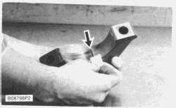
h. Carefully remove the cap but do not remove the Plastigage. Measure the width of the Plastigage while it is in the bearing cap or on the crankshaft journal, See photograph.
i. Remove all the Plastigage before reinstalling the cap.
NOTE: When using Plastigage, the readings can sometimes be unclear. For example, all parts of the Plastigage are not the same width. Measure the major width to make sure they are within the specification range.
Thu Apr 11 00:08:47 UTC+0530 2024
Product: TRUCK ENGINE
Model: 3306C TRUCK ENGINE 7RJ
Configuration: 3306C Truck Engine 7RJ00001-UP
Disassembly and Assembly
3306C DIESEL TRUCK ENGINE
Media Number -SEBR0552-00
Piston Cooling Orifices
SMCS - 1307-010
Date -01/01/1992
Remove And Install Piston Cooling Orifices
Start By:
a. remove crankshaft
NOTICE
Keep all parts clean from contaminants. Contaminants put into the system may cause rapid wear and shortened component life.
-11/10/2001
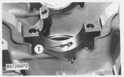
NOTE: The No. 2 and 6 main bearing bosses each have two orifices. The No. 3 and 5 main bearing bosses each have one orifice. A replacement is necessary only if they are damaged. Normally it will only be necessary to be sure the orifices are clean.
1. Use a soft punch to remove the orifices from the cylinder block.
NOTE: The following steps are to install the piston cooling orifices.
2. Use tool (A) to install piston cooling orifice (1) (small end first). Install the orifices in main bearing bosses until they are against the counterbore.
3. Make sure that the passage is open after the piston cooling orifice is installed.
End By:
a. install crankshaft Copyright 1993 - 2024 Caterpillar Inc. All Rights Reserved. Private Network For SIS Licensees. Thu Apr 11 00:08:32 UTC+0530 2024
Product: TRUCK ENGINE
Model: 3306C TRUCK ENGINE 7RJ
Configuration: 3306C Truck Engine 7RJ00001-UP
Disassembly and Assembly
3306C DIESEL TRUCK ENGINE
Media Number -SEBR0552-00
Rear Power Takeoff
SMCS - 1165-010
Remove And Install Rear Power Takeoff
Start By:
a. remove flywheel housing
NOTICE
Keep all parts clean from contaminants. Contaminants put into the system may cause rapid wear and shortened component life.
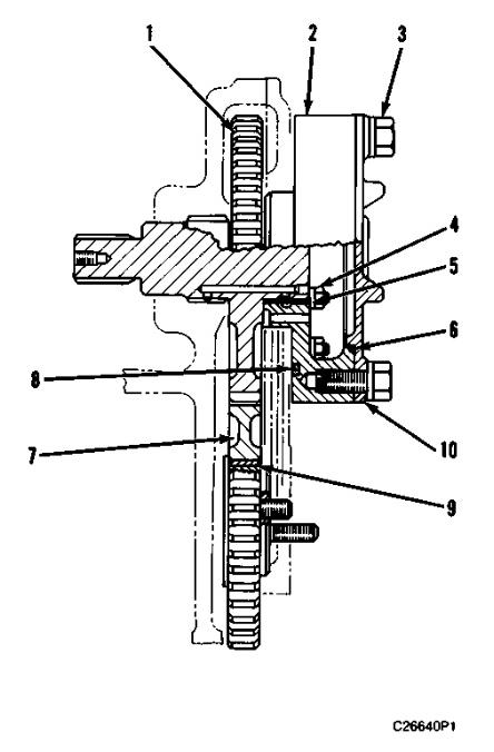
1. Remove idler gear (7).
2. Remove the gear train housing, which has the Power Take Off, (PTO), mounted to it.
3. Remove bolts (3) and drive opening cover (10). Remove PTO gear assembly (1). Remove six nuts (4).
4. Remove adapter assembly (2) and o-ring seals (6) and (8).
5. If necessary, remove bearing sleeves (9) and (5) for the idler gear and the PTO gear (1). Make note of the positioning of the oil holes in the bearings. Proper location of the holes during installation is necessary for lubrication.
NOTE: The following steps are for the installation of the PTO Assembly.
6. Install bearing sleeves (5) and (9). Be sure to align oil holes.
This is the sample of the manual click on the download link for complete manual
DOWNLOAD LINK
For some reason if link does not work download this pdf and then click