



Product: MARINE ENGINE
Model: 3304 MARINE ENGINE 05B
Configuration: 3304 MARINE ENGINE 05B01387-02056
Disassembly and Assembly
26SI Series Alternator
Alternator - Assemble
SMCS - 1405-016
Assembly Procedure
Note: Cleanliness is an important factor. Before assembly, all parts should be thoroughly cleaned in cleaning fluid. Allow the parts to air dry. Wiping cloths or rags should not be used to dry parts. Lint may be deposited on the parts which may cause later trouble. Inspect all parts. If any parts are worn or damaged, use new parts for replacement.
Note: Do not strike the diodes. The shock of such an impact can damage the diodes. Use proper tools in order to press the diodes in the mountings.
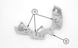
Illustration 1
1. Install 3 diodes (11) in heat sink (12) .
g00628072
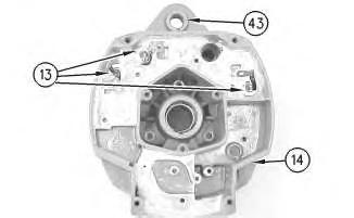
Illustration 2
g00628068
Note: Do not strike the bushing. Shocks from striking the housing can cause damage.
2. Press bushing (43) in housing (14) .
3. Install 3 diodes (13) in housing (14) .
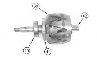
Illustration 3
This is the sample of the manual click on the download link for complete manual
DOWNLOAD LINK
For some reason if link does not work download this pdf and then click
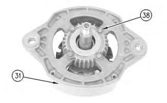
Illustration 4
g00628063
7. Press housing (31) on rotor (39) and bearing (40) .
8. Install 4 screws (38) in housing (31) .
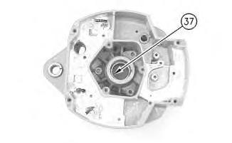
Illustration 5
g00628057
Note: Do not strike the bearing. Shocks from striking the housing can cause damage.
9. Install the inner race. Press bearing (37) into the housing.
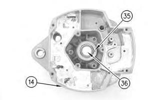
Illustration 6
10. Press cap (36) in housing (14) .
g00628043
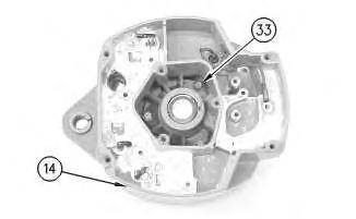
Illustration 7
g00628041
11. Install the coil and support (34) in housing (14). Guide the field leads and the grommet through the hole as the coil is installed in housing (14). Install 3 screws (33) .
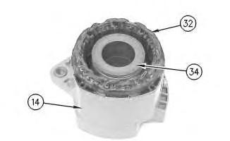
Illustration 8
g00628037
12. Press the stator (32) and housing (14) together. Guide the stator leads and the grommet through the hole as the stator is installed in housing (14) .
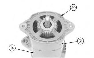
Illustration 9
g00628035
Note: Do not damage exposed stator windings or field windings. Bumping the windings or scraping the windings may break the insulation. Broken insulation may create a short circuit or a ground.
13. Join housing (31) and housing (14). Install 4 bolts (30) .
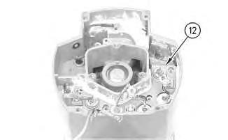
Illustration 10
g00627853
Note: Many of the alternator's internal components are covered with dielectric grease. If the grease is removed, reapply the grease.
11
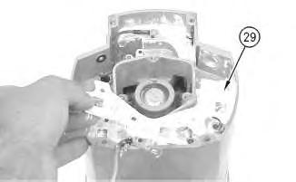
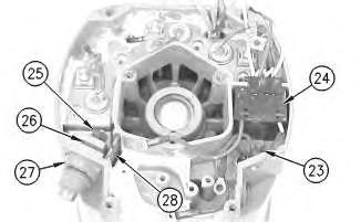
14. Install Insulator (29). Install the heat sink and diode assembly (12) in housing (14) .
12
15. Install separator (28) .
16. Install alternator output terminal (27). Install insulator (26). Install the nut and washer (25) .
17. Install diode trio (24) and install screw (23) .
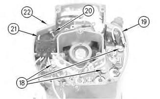
Illustration 13
g00627832
18. Install the 3 screws and insulators (18). Connect wire (19) .
19. If the "R" terminal is used, install the following components: nut (20), lead (21), the washer and terminal (21) .
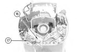
Illustration 14
g00627820
20. Install the screw and insulator (16). Connect capacitor lead (17) .
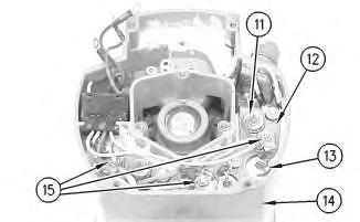
Illustration 15
g00627810
Note: The 3 output diodes (11) are located in heat sink (12). These diodes are identical in polarity. Diode (11) has red insulation on the wire. The 3 ground diodes (13) are located in housing (14). These diodes are identical in polarity. Diode (13) has black insulation on the wire.
21. Connect 6 diode leads. Connect 3 phase leads. Connect 3 stator phase leads. Install 3 nuts (15).
Table 1
Alternator Ground
Negative
Current Flow of the Output Diodes
Lead to the Heat Sink
Current Flow of the Ground Diodes
Housing to the Lead Red Wire Black Wire
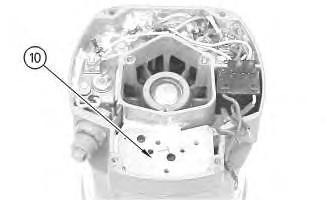
Illustration 16
22. Install mounting plate (10).
g00627808
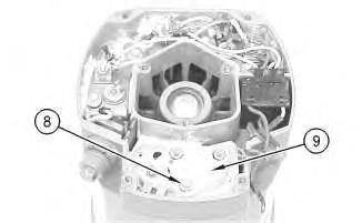
Illustration 17
23. Install regulator (9) .
24. Install grounded mounting screw (8) .
g00627804
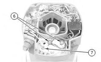
18
25. Install 2 insulated screws (6). Connect the 3 leads.
Note: The regulator and the mounting plate are coated with dielectric grease. If the grease is removed, reapply the grease.
26. Install nut (7) and connect the wire.
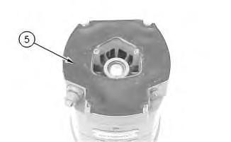
19
27. Install gasket (5) .
20
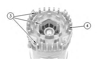
28. Position cover (4). Install 7 screws (3) .
21
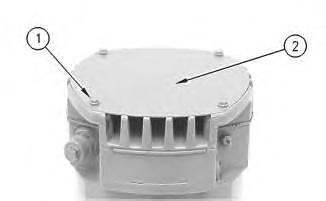
29. Position plate (2). Install 4 screws (1) .
30. Install the fan, the pulley, the washer, and the pulley nut.
Product: MARINE ENGINE
Model: 3304 MARINE ENGINE 05B
Configuration: 3304 MARINE ENGINE 05B01387-02056
Disassembly and Assembly
26SI Series Alternator
Alternator - Disassemble
SMCS - 1405-015
Disassembly Procedure
Table 1 Required Tools
Start By:
A. Remove the alternator. Refer to Disassembly and Assembly, "Alternator - Remove" for the machine that is being serviced.
Note: Cleanliness is an important factor. Before the disassembly procedure, the exterior of the component should be thoroughly cleaned. This will help to prevent dirt from entering the internal mechanism.
1. Remove the pulley nut, the washer, the pulley, and the fan.
Illustration 1
2. Remove 4 screws (1). Remove plate (2) .
Illustration 2
3. Remove 7 screws (3). Remove cover (4) .
Illustration 3
4. Remove gasket (5) .
Illustration 4
5. Remove 2 insulated screws (6). Remove the 3 leads.
Note: The regulator and the mounting plate are coated with dielectric grease. If the grease is removed, reapply the grease.
6. Remove nut (7) .
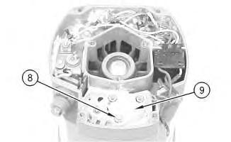
Illustration 5
7. Remove grounded mounting screw (8) .
8. Remove regulator (9) .
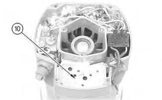
Illustration 6
g00627808
9. Remove mounting plate (10). The mounting plate may be stuck to the regulator.
Illustration 7
g00627810
Note: The 3 output diodes (11) are located in heat sink (12). These diodes are identical in polarity. Diode (11) has red insulation on the wire. The 3 ground diodes (13) are located in housing (14). These diodes are identical in polarity. Diode (13) has black insulation on the wire.
10. Remove 3 nuts (15). Disconnect 3 stator phase leads. Disconnect 3 phase leads. Disconnect 6 diode leads.
Table 2
Alternator Ground Current Flow of the Output Diodes Current Flow of the Ground Diodes
Negative
Lead to the Heat Sink Housing to the Lead Red Wire Black Wire
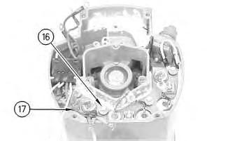
Illustration 8
g00627820
11. Remove the screw and insulator (16). Disconnect capacitor lead (17) .
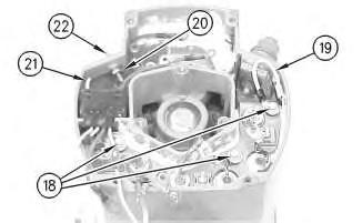
Illustration 9
g00627832
12. Remove the 3 screws and insulators (18). Disconnect wire (19) .
13. If the "R" terminal is used, remove the following components: nut (20), lead (21), the washer and terminal (21) .
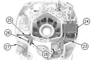
Illustration 10
14. Remove screw (23) and remove diode trio (24) .
15. Remove the nut and washer (25). Remove insulator (26). Remove alternator output terminal (27) .
16. Remove separator (28) .
Illustration 11
g00627853
Note: Many of the alternator's internal components are covered with dielectric grease. If the grease is removed, reapply the grease.
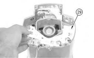
Illustration 12
g00627855
17. Remove the heat sink and diode assembly (12) from housing (14). Insulator (29) may be stuck to heat sink (12) .
Illustration 13
g00628035
Note: Do not damage exposed stator windings or field windings. Bumping the windings or scraping the windings may break the insulation. Broken insulation may create a short circuit or a ground.
18. Remove 4 bolts (30). Carefully separate housing (31) from housing (14) .

Illustration 14
g00628037
19. Pull apart stator (32) and housing (14). Guide the stator leads and the grommet through the hole as the stator is removed from housing (14) .
Illustration 15
g00628041
20. Remove 3 screws (33). Remove the coil and support (34) from housing (14). Guide the field leads and the grommet through the hole as the coil is removed from housing (14) .
Illustration 16
g00628043
21. Position a small screwdriver in slot (35). Pry cap (36) from housing (14) .
Illustration 17
g00628057
Note: Do not strike the bearing. Shocks from striking the housing can cause damage.
22. Wipe the excess grease from the bearing well. Press bearing (37) into the housing. Remove the inner race.
Illustration 18
23. Remove 4 screws (38) from housing (31) .
g00628063
24. Lift rotor (39) and bearing (40) from housing (31) .
Illustration 19
25. Pull bearing (40) from rotor (39) .
26. Pull retainer (41) from rotor (39) .
27. Pull collar (42) from rotor (39) .
g00628067
Illustration 20
g00628068
Note: Do not strike the bushing. Shocks from striking the housing can cause damage.
28. Press bushing (43) from housing (14) .
Note: Do not strike the diodes. The shock of such an impact can damage the diodes. Use proper tools in order to press or pull the diodes from the mountings. As much as 890 N (200 lb) of force may be needed to remove a diode.
29. Remove 3 diodes (13) from housing (14) .
Illustration 21
30. Remove diode (11) from heat sink (12) .
g00628072
Copyright 1993 - 2024 Caterpillar Inc. All Rights Reserved. Private Network For SIS Licensees. Fri Apr 5 09:16:00 UTC+0530 2024
Product: MARINE ENGINE
Model: 3304 MARINE ENGINE 05B
Configuration: 3304 MARINE ENGINE 05B01387-02056
General Service Information
D330, D333, 3304, 3306 INDUSTRIAL
Media Number -SEBR0517-00
& MARINE ENGINES
Date -01/10/1979
General Instructions
SMCS - 1307-10
Updated -11/10/2001
The following instructions will prove helpful to disassemble and assemble engine components. The information should be read and then referred to as necessary.
Cleanliness
Whenever hydraulic, fuel, lubricating oil or air lines are disconnected, clean the point of disconnection and the adjacent area. As soon as the disconnection is made, cap, plug or tape the line or opening to prevent entry of foreign material. The same recommendations for cleaning and covering apply when access covers or inspection plates are removed.
Clean and inspect all parts. Be sure all passages and holes are open. Cover all parts to keep them clean. Be sure parts are clean when installed. Leave new parts in their containers until ready for assembly.
Removal And Installation
Unless otherwise specified, all removals should be accomplished using an adjustable lifting beam. All supporting members (chains and cables) should be parallel to each other and as near perpendicular as possible to the top of the object being lifted.

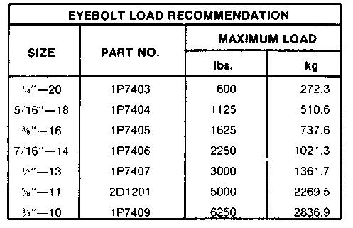
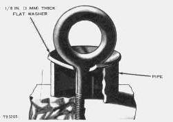
When it is necessary to remove a component on an angle, remember that the capacity of an eyebolt diminishes as the angle between the supporting members and the object becomes less than 90°. Eyebolts and brackets should never be bent and should only have stress in tension. A length of pipe and a washer can be used, as shown, to help relieve these stresses on eyebolts.
Forged eyebolts are available. Each size eyebolt has a maximum load recommendation.
Some removals require the use of lifting fixtures to obtain proper balance and to provide safe handling.
If a part resists removal, check to be certain all nuts and bolts have been removed and that an adjacent part is not interfering.
Disassembly And Assembly
When assembling an engine, complete each step in turn. Do not partially assemble one part and start assembling some other part. Make all adjustments as recommended. Always check the job after it is completed to see nothing has been overlooked.
Lubrication For A Rebuilt Engine
It is very important for a rebuilt engine to have "adequate" (needed) lubrication during the first seconds of operation. A "dry start" (without needed lubrication) on a rebuilt engine can cause bearing damage.
When an engine is rebuilt with new parts, oil is put on each part as it is installed. This is generally enough lubrication for engine start-up. However, this lubrication may not be enough or may be lost if the rebuilt engine is placed in storage for any length of time.
To prevent the possibility of a "dry start" and bearing damage during the first seconds of running, use the 1P540 Flow Checking Tool Group and shop air pressure to pressure lubricate (fill the main oil passage with oil under pressure) all rebuilt engines.
Procedure for Pressure Lubrication
1. Clean the tank of the 1P540 Flow Checking Tool Group thoroughly, and set the pressure regulator to 35 ± 5 psi (240 ± 35 kPa).
Air pressure should not be more than 50 psi (345 kPa) at any time.
2. Put engine oil in the tank.
3. Connect the tooling to the main oil passage of the engine.
4. Add air pressure to the tank, with the regulator set at 35 ± 5 psi (240 ± 35 kPa). Although the tank does have a hand pump, it is difficult to get enough air pressure to do the job with the hand pump. Therefore, use of shop air is recommended.
5. Let the engine oil flow into the oil passage under pressure.
Fill the crankcase with the correct oil. The amount of oil used in the pressure lubrication procedure must be subtracted from the recommended refill capacity in the Lubrication and Maintenance Guide. If the engine is not going to be used for a long time, do the above procedure again before the first starting.
If shop air is not available for charging the tank, the hand pump may be used to get the minimum required pressure.
NOTICE
Do not use the same 1P540 Flow Checking Tool Group for both "pressure lubrication application" and for checking fuel flow. Incorrect cleaning is probable if the tool is used for both fuel and lube oil. Even a minute amount of dirt in the fuel system can cause fuel nozzle failure.
Initial Operation After Engine Reconditioning
The quality of oil control components used in Caterpillar engines is such that, following engine reconditioning (with Caterpillar Service Parts), only an initial operational check is necessary before continued operation in normal service.
This is the sample of the manual click on the download link for complete manual
DOWNLOAD LINK
For some reason if link does not work download this pdf and then click