


Note: Use Bookmarks panel to navigate
Product: EXCAVATOR
Model: 329F L EXCAVATOR ERL
Configuration: 329F L Excavator ERL00001-UP (MACHINE) POWERED BY C7.1 Engine
Disassembly and Assembly
326F, 329F and 330F Excavators Machine Systems
Media Number -UENR3313-09
Main Hydraulic Pump - Disassemble
SMCS - 5070-015
S/N - B321-UP
S/N - ERL1-UP
S/N - GHT1-UP
S/N - GKK1-UP
S/N - HBT1-UP
S/N - HCJ1-UP
S/N - HCK1-UP
S/N - JFR1-UP
S/N - JHF1-UP
S/N - KFA1-UP
S/N - LBN1-UP
S/N - LCG1-UP
S/N - MBX1-UP
S/N - RCN1-UP
S/N - SGK1-UP
S/N - TMR1-UP
S/N - TPG1-UP
S/N - WBA1-UP
S/N - WGL1-UP
S/N - XFK1-UP
S/N - YHA1-UP
S/N - ZNN1-UP
Disassembly Procedure
Table 1
Required Tools
Start By:
a. Remove the pump drive coupling.
Note: Only the right pump control is equipped with the proportional reducing valve. The left pump control starts with Step 4.
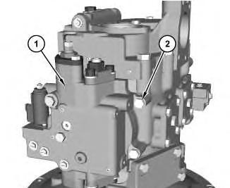
Illustration 1 g02405999
1. Remove bolts (2) and pump control (1).
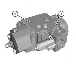
Illustration 2 g02406017 Right Pump Only
2. Remove proportional reducing valve (3) from pump control (1).
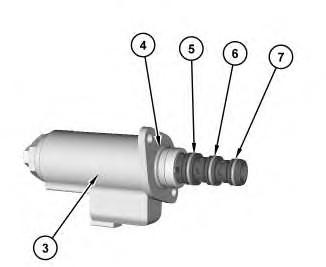
Illustration 3
g02406097 Right Pump Only
3. Remove O-ring seal (7), O-ring seal (6), O-ring seal (5), and O-ring seal (4) from the proportional reducing valve (3).
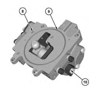
Illustration 4 g02406264
4. Remove O-ring seals (8) and O-ring seal (9). Remove nut (10) from the pump control.
This is the sample of the manual click on the download link for complete manual
DOWNLOAD LINK
For some reason if link does not work download this pdf and then click
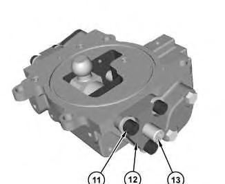
5
5. Measure the length of screw (13) for installation purposes. Remove screw (13). Remove bolts (11). Remove cover (12) from the pump control.
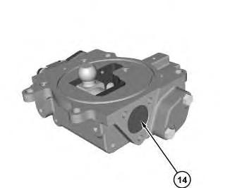
Illustration 6
6. Remove stopper (14) from the pump control.
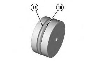
Illustration 7
7. Remove O-ring seal (15) and backup ring (16) from the stopper.
8. Repeat Step 4 through Step 7 for the other side of the pump control.
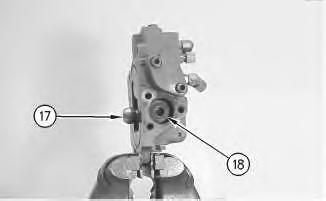
Illustration 8
g00706239
9. Place the pump control in a soft jawed vise. Support pin assembly (17). Remove piston (18) from the pump control. Remove pin assembly (17) from the pump control.
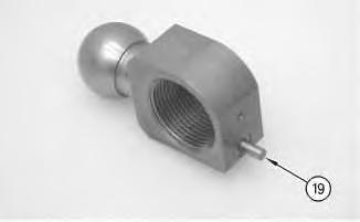
Illustration 9
10. Remove dowel pin (19) from the pin.
g00706243
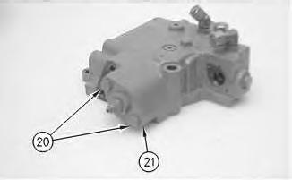
Illustration 10
g00706249
11. Remove bolts (20). Remove cover assembly (21) from the pump control.
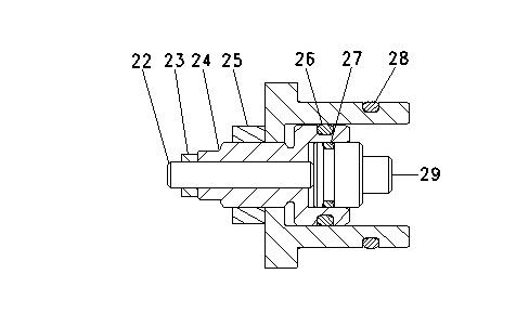
Illustration 11
g00882599
Personal injury can result from parts and/or covers under spring pressure.
Spring force will be released when covers are removed. Be prepared to hold spring loaded covers as the bolts are loosened.
12. Remove O-ring seal (28). Remove retainer (29). Remove O-ring seal (27) from the retainer. Remove nut (23) and nut (25). Remove setscrew (22). Remove adjuster (24). Remove Oring seal (26) from the adjuster.
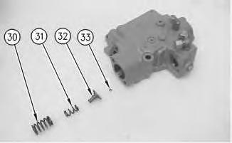
Illustration 12
13. Remove spring (30) and spring (31) from the pump control. Remove guide (32) from the pump control. Remove ball (33) from the guide.
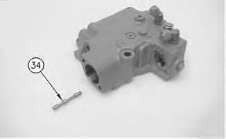
Illustration 13
g00706265
14. Remove pilot piston (34) from the pump control.
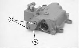
Illustration 14
g00706266
Personal injury can result from parts and/or covers under spring pressure.
Spring force will be released when covers are removed.
Be prepared to hold spring loaded covers as the bolts are loosened.
15. Remove bolts (35). Remove cover (36) from the pump control.
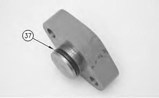
Illustration 15
16. Remove O-ring seal (37) from the cover.
g00706267
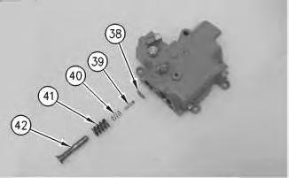
Illustration 16
g00882608
17. Remove control piston (42), spring (41), spring (40), spool (39), and shims (38) from the pump control.
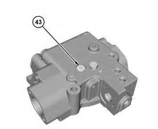
Illustration 17
18. Remove pin (43) from the pump control.
g02406460
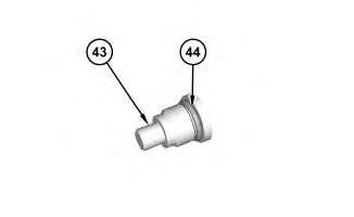
Illustration 18
g02406463
19. Remove O-ring seal (44) from the pin (43).
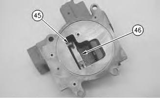
Illustration 19
g00706273
20. Remove sleeve (45) and control linkage (46) from the pump control.
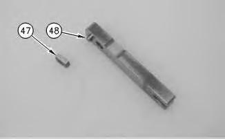
Illustration 20
g00882609
21. Remove slide plate (47) and dowel (48) from the control linkage.
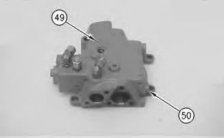
Illustration 21
g00706275
22. Remove plugs (49). Remove three plugs (50) from the pump control.
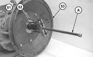
Illustration 22
g01200390
23. Use Tooling (A) to remove seal assembly (52). Remove bolts (51), bell housing (53), and the gasket.
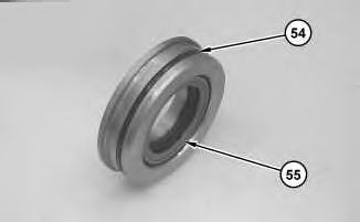
Illustration 23
g01200392
24. Remove O-ring seal (54) and lip seal (55) from the seal assembly.
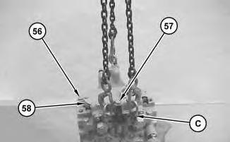
Illustration 24
g01200457
25. Attach Tooling (C) and a suitable lifting device to head (10). Remove bolts (56) and (57) and head (58). The weight of head (58) is approximately 41 kg (90 lb).
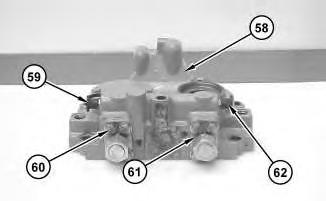
Illustration 25
g01200458
26. Remove caps (59) from nipples (62). Remove nipples (62), bolts (60), and covers (61) from head (58).
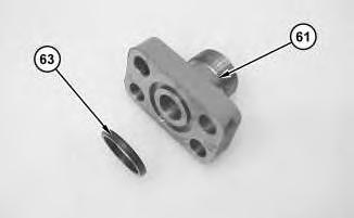
Illustration 26
g01200459
27. Remove O-ring seal (63) from covers (61).
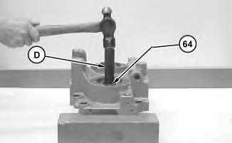
Illustration 27
g01200460
28. Use Tooling (D) to remove bearings (64) from the head.
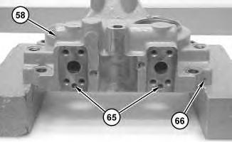
Illustration 28
g01200462
29. Remove plugs (65) and (66) from head (58).
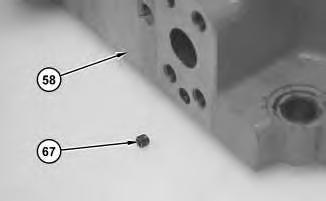
Illustration 29
30. Remove orifices (67) from head (58).
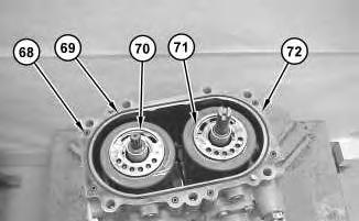
Illustration 30
31. Remove O-ring seals (68) and (69) from pump housing (72). Remove port plates (70) and (71).
Note: The port plates must be installed in the original position during assembly.
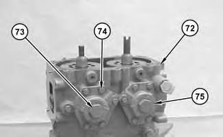
Illustration 31
g01200473
32. Remove plugs (73), bolts (74), and covers (75) from pump housing (72).
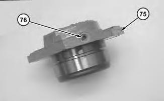
Illustration 32
33. Remove plug (76) from covers (75).
g01200475
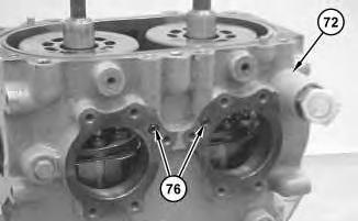
Illustration 33
g01200478
34. Remove O-ring seals (76) from pump housing (72).
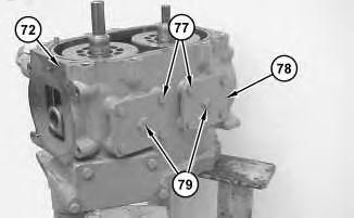
Illustration 34
g01200477
35. Remove plugs (79), bolts (77), and covers (78) from pump housing (72).
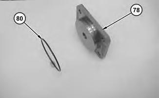
35
36. Remove O-ring seal (80) from covers (78).
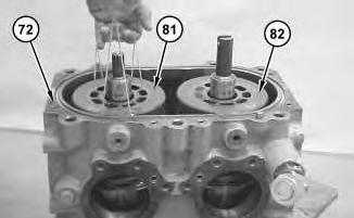
Illustration 36
g01200482
37. Remove barrel assemblies (81) and (82) from pump housing (72).
Note: It may be necessary to use string to aid in the removal procedure. The barrel assemblies must be installed in the original position during assembly.
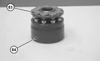
Illustration 37
g01200485
38. Mark piston assemblies (83) and barrel (84) for assembly. Remove piston assembly (83) from barrel (84).
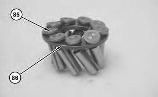
Illustration 38
g01200486
39. Remove pistons (85) from piston plate (86).
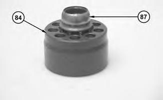
Illustration 39
40. Remove cap (87) from barrel (84).
g01200487
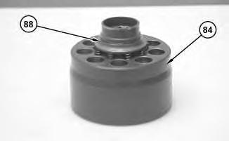
Illustration 40
41. Remove retainer (88) from barrel (84).
g01200488
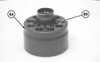
Illustration 41
42. Remove springs (89) from barrel (84).
43. Repeat Step 38 through Step 42 for the remaining barrel assembly.
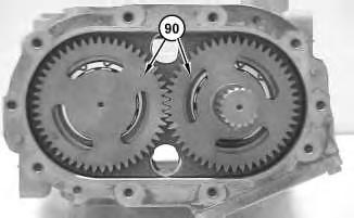
Illustration 42
g01200492
Note: The pump has been removed from Tooling (B) for photographic purposes only.
44. Use Tooling (E) to remove retaining rings (90).
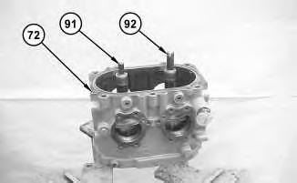
Illustration 43
g01200494
45. Remove shaft assemblies (91) and (92) from pump housing (72).
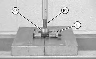
Illustration 44
g01200497
46. Use Tooling (F) and a suitable press to remove bearing (93) from shaft assembly (91).
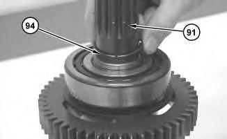
Illustration 45
g01200498
47. Remove ring (94) from shaft assembly (91).

Illustration 46 g01200501
48. Use Tooling (G) and a suitable press to remove bearing (95) from shaft assembly (91).
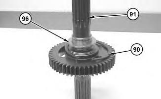
47
49. Remove spacer (96) and retaining ring (90) from shaft assembly (91).
50. Repeat Step 46 through Step 49 for shaft (92).
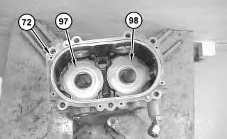
Illustration 48
g01200504
51. Remove swashplate assemblies (97) and (98) from pump housing (72).
Note: The swashplate assemblies must be installed in the original position during assembly.
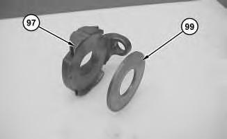
Illustration 49
g01200506
52. Remove plate (99) from swashplate assembly (97).
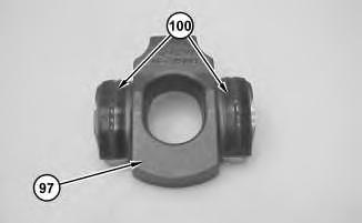
Illustration 50
g01200507
53. Remove bearings (100) from swashplate assembly (97).
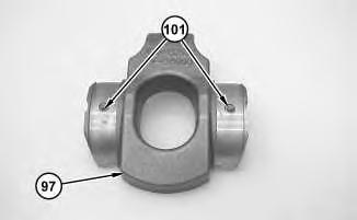
Illustration 51
g01200509
54. Remove dowel pins (101) from swashplate (97).
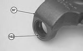
Illustration 52
g01200510
55. Remove bearing (102) from swashplate (97).
56. Repeat Step 52 through Step 55 for swashplate assembly (98).
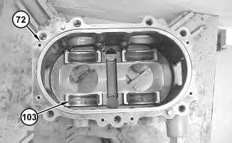
Illustration 53
g01200511
57. Remove bearings (103) from pump housing (72).
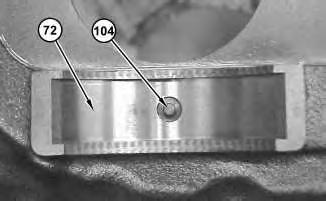
Illustration 54
g01200512
58. Remove guide pins (104) from pump housing (72).
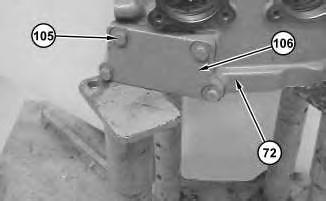
Illustration 55
g01200514
59. Remove bolts (105) and cover (106) from pump housing (72).
This is the sample of the manual click on the download link for complete manual
DOWNLOAD LINK
For some reason if link does not work download this pdf and then click