


This is the sample of the manual click on the download link for complete manual
DOWNLOAD LINK
For some reason if link does not work download this pdf and then click

Product: EXCAVATOR
Model: 325D EXCAVATOR GPB
Configuration: 325D L & LN Excavator GPB00001-UP (MACHINE) POWERED BY C7 Engine
Disassembly and Assembly
C7 Engines for Caterpillar Built Machines
Media Number -RENR9218-14
Date -01/06/2014
Electric Starting Motor - Remove and Install
SMCS - 1453-010
Removal Procedure
Updated -30/06/2020
Accidental engine starting can cause injury or death to personnel working on the equipment.
To avoid accidental engine starting, disconnect the battery cable from the disconnected battery cable end in order to prevent contact with other metal surfaces which could activate the engine electrical system.
Place a Do Not Operate tag at the Start/Stop switch location to inform personnel that the equipment is being worked on.
1. Disconnect the batteries.
2. Place identification marks on all of the harness assemblies that are connected to the electric starting motor and the solenoid.
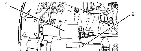
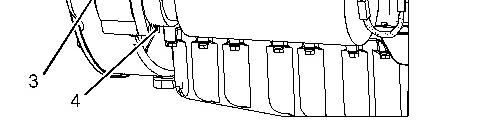
1 g01155364
3. Disconnect the harness assemblies from solenoid (1).
4. Attach a suitable lifting device to electric starting motor (2). The weight of electric starting motor (2) is approximately 26 kg (57 lb).
5. Remove bolts (4). Remove electric starting motor (2) and gasket (3).
Installation Procedure
2
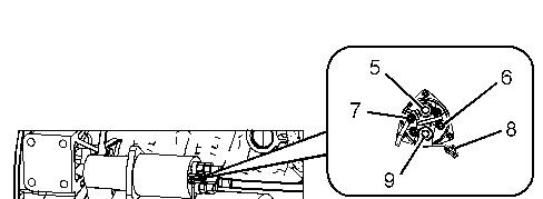
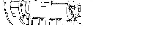
Illustration 3 g01155365
1. Attach a suitable lifting device to electric starting motor (2). The weight of electric starting motor (2) is approximately 26 kg (57 lb).
2. Position gasket (3) and electric starting motor (2) on the flywheel housing. Install bolts (4).
3. Position the harness assembly on solenoid (1) and install nut (5). Tighten the nut to a torque of 31 ± 4 N·m (23 ± 3 lb ft).
4. Position the harness assembly on solenoid (1) and install nut (7). Tighten the nut to a torque of 2.25 ± 0.25 N·m (20 ± 2 lb in).
5. Position the harness assembly on solenoid (1) and install nut (6). Tighten the nut to a torque of 2.25 ± 0.25 N·m (20 ± 2 lb in).
6. If necessary, install the connector and install nut (9) and bolt (8). Tighten the nut to a torque of 31 ± 4 N·m (23 ± 3 lb ft). Tighten the bolt to a torque of 8 ± 3 N·m (71 ± 27 lb in).
7. Connect the batteries.
Copyright 1993 - 2024 Caterpillar Inc. All Rights Reserved. Private Network For SIS Licensees. Tue Mar 12 20:19:21 UTC+0530 2024
Product: EXCAVATOR
Model: 325D EXCAVATOR GPB
Configuration: 325D L & LN Excavator GPB00001-UP (MACHINE) POWERED BY C7 Engine
Disassembly and Assembly
C7 Engines for Caterpillar Built Machines
Media Number -RENR9218-14
Date -01/06/2014
Alternator - Remove and Install
SMCS - 1405-010
Removal Procedure
Updated -30/06/2020
Accidental engine starting can cause injury or death to personnel working on the equipment.
To avoid accidental engine starting, disconnect the battery cable from the disconnected battery cable end in order to prevent contact with other metal surfaces which could activate the engine electrical system.
Place a Do Not Operate tag at the Start/Stop switch location to inform personnel that the equipment is being worked on.
1. Disconnect the battery.
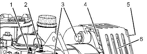
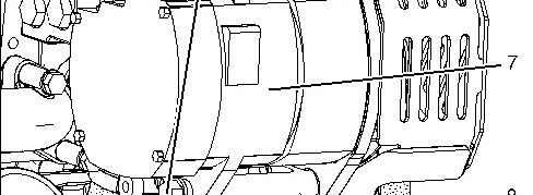

Illustration 1 g01155290
2. Place an index mark on all harness assemblies that are connected to alternator (7). Disconnect harness assembly (1) and harness assembly (2).
3. Remove bolt (5) and guard assembly (6).
4. Remove drive belt (8).
5. Remove top bolt (3) and spacer (4). Remove lower bolt (3).
6. Remove alternator (7).
Installation Procedure
Illustration 2 g01155290
1. Position alternator (7) on the mounting bracket. Place lower bolt (3) in position. Install upper bolt (3) and spacer (4). Tighten upper bolt (3) and spacer (4) to the standard torque. Tighten lower bolt (3) to the standard torque.
2. Install drive belt (8).
3. Position guard assembly (6) and install bolt (5).
4. Connect harness assembly (1) and harness assembly (2) to alternator (7). Use the index marks to correctly connect the harness assemblies. Tighten the nut for harness assembly (1) to a torque of 6.2 ± 0.6 N·m (55 ± 5 lb in). Tighten the nut for harness assembly (2) to a torque of 2.25 ± 0.25 N·m (20 ± 2 lb in).
5. Connect the battery.
Copyright 1993 - 2024 Caterpillar Inc.
Network For SIS Licensees. Tue Mar 12 20:19:11 UTC+0530 2024
Product: EXCAVATOR
Model: 325D EXCAVATOR GPB
Configuration: 325D L & LN Excavator GPB00001-UP (MACHINE) POWERED BY C7 Engine
Disassembly and Assembly
C7 Engines for Caterpillar Built Machines
Media Number -RENR9218-14 Publication Date -01/06/2014 Date Updated -30/06/2020
Electronic Control Module - Remove and Install
SMCS - 1901-010
Removal Procedure
Accidental engine starting can cause injury or death to personnel working on the equipment.
To avoid accidental engine starting, disconnect the battery cable from the disconnected battery cable end in order to prevent contact with other metal surfaces which could activate the engine electrical system.
Place a Do Not Operate tag at the Start/Stop switch location to inform personnel that the equipment is being worked on.
1. Disconnect the battery.
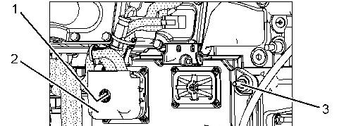
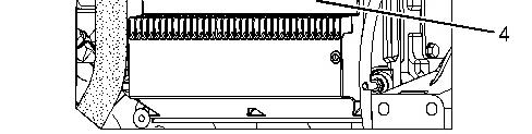
Illustration 1 g01155236
2. Loosen allen head screw (1). Disconnect harness assembly (2) from electronic control module (4).
3. Remove nuts (3), the washers, the isolation mounts, electronic control module (4), and the ground strap.
Installation Procedure
Illustration 2 g01155236
1. Position the isolation mounts on electronic control module (4). Position the washers, the ground strap, and electronic control module (4) on the engine and install nuts (3).
2. Connect harness assembly (2) to electronic control module (4). Install allen head screw (1) and tighten to a torque of 6 ± 1 N·m (53 ± 9 lb in).
3. Connect the battery.
Copyright 1993 - 2024 Caterpillar Inc. All Rights Reserved. Private Network For SIS Licensees. Tue Mar 12 20:19:01 UTC+0530 2024
Product: EXCAVATOR
Model: 325D EXCAVATOR GPB
Configuration: 325D L & LN Excavator GPB00001-UP (MACHINE) POWERED BY C7 Engine
Disassembly and Assembly
C7 Engines for Caterpillar Built Machines
Media Number -RENR9218-14
-01/06/2014
Fan Drive Mounting Group - Remove and Install
SMCS - 1359-010
Removal Procedure
Updated -30/06/2020
Accidental engine starting can cause injury or death to personnel working on the equipment.
To avoid accidental engine starting, disconnect the battery cable from the disconnected battery cable end in order to prevent contact with other metal surfaces which could activate the engine electrical system.
Place a Do Not Operate tag at the Start/Stop switch location to inform personnel that the equipment is being worked on.
1. Disconnect the battery.
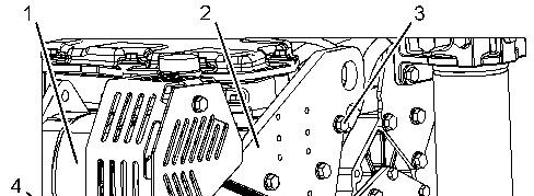
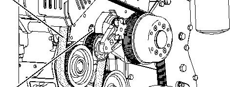

Illustration 1 g01155174
2. Remove drive belt (4) from the engine.
3. Place identification marks on the harness assemblies that are connected to alternator (1).
4. Disconnect the harness assemblies from alternator (1).
5. Attach a suitable lifting device to fan drive mounting group (2). The weight of fan drive mounting group (2) is approximately 34 kg (75 lb).
6. Remove bolts (3) and bolts (5).
7. Remove fan drive mounting group (2).
Installation Procedure
Illustration 2 g01155174
1. Attach a suitable lifting device to fan drive mounting group (2). The weight of fan drive mounting group (2) is approximately 34 kg (75 lb). Position fan drive mounting group (2) on the engine.
2. Install bolts (3) and bolts (5). Torque the bolts according to the following procedure. Finger tighten bolts (5). Finger tighten bolts (3). Tighten bolts (5) and bolts (3) to the standard torque.
3. Connect the harness assemblies to alternator (1).
4. Install drive belt (4) on the engine.
5. Connect the battery.
1993 - 2024 Caterpillar Inc.
Tue Mar 12 20:18:49 UTC+0530 2024
Product: EXCAVATOR
Model: 325D EXCAVATOR GPB
Configuration: 325D L & LN Excavator GPB00001-UP (MACHINE) POWERED BY C7 Engine
Disassembly and Assembly
C7 Engines for Caterpillar Built Machines
Media Number -RENR9218-14 Publication Date -01/06/2014 Date Updated -30/06/2020
Inlet Air Temperature Sensor - Remove and Install
SMCS - 1921-010
Removal Procedure NOTICE
Keep all parts clean from contaminants.
Contaminants may cause rapid wear and shortened component life.
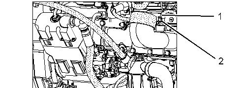
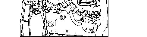
Illustration 1
1. Disconnect harness assembly (1).
2. Remove inlet air temperature sensor (2).
3. Remove the O-ring seal from inlet air temperature sensor (2).
Installation Procedure
NOTICE
Keep all parts clean from contaminants.
Contaminants may cause rapid wear and shortened component life.
Illustration 2 g01155072
1. Install a new O-ring seal on inlet air temperature sensor (2).
2. Install inlet air temperature sensor (2) and tighten to a torque of 20 ± 5 N·m (15± 4 lb ft).
3. Connect harness assembly (1).
Copyright 1993 - 2024 Caterpillar Inc.
Rights Reserved.
Network For SIS Licensees. Tue Mar 12 20:18:38 UTC+0530 2024
Product: EXCAVATOR
Model: 325D EXCAVATOR GPB
Configuration: 325D L & LN Excavator GPB00001-UP (MACHINE) POWERED BY C7 Engine
Disassembly and Assembly
C7 Engines for Caterpillar Built Machines
Media Number -RENR9218-14 Publication Date -01/06/2014 Date Updated -30/06/2020
i02306076
Turbocharger Outlet Pressure Sensor - Remove and Install
SMCS - 1917-010
Removal Procedure NOTICE
Keep all parts clean from contaminants.

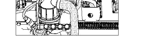
Contaminants may cause rapid wear and shortened component life. Illustration 1
1. Disconnect harness assembly (1).
2. Remove turbocharger outlet pressure sensor (2).
3. Remove the O-ring seal from turbocharger outlet pressure sensor (2).
Installation Procedure
NOTICE
Keep all parts clean from contaminants.
Contaminants may cause rapid wear and shortened component life.
Illustration 2 g01155027
1. Install a new O-ring seal on turbocharger outlet pressure sensor (2).
2. Install turbocharger outlet pressure sensor (2) and tighten to a torque of 10 ± 2 N·m (89 ± 18 lb in).
3. Connect harness assembly (1).
Tue Mar 12 20:18:27 UTC+0530 2024
Product: EXCAVATOR
Model: 325D EXCAVATOR GPB
Configuration: 325D L & LN Excavator GPB00001-UP (MACHINE) POWERED BY C7 Engine
Disassembly and Assembly
C7 Engines for Caterpillar Built Machines
Media Number -RENR9218-14
Speed/Timing Sensor - Remove and Install
SMCS - 1907-010; 1912-010
Removal Procedure
NOTICE
Care must be taken to ensure that fluids are contained during performance of inspection, maintenance, testing, adjusting, and repair of the product. Be prepared to collect the fluid with suitable containers before opening any compartment or disassembling any component containing fluids.
Refer to Special Publication, PERJ1017, "Dealer Service Tool Catalog" for tools and supplies suitable to collect and contain fluids on Cat® products.
Dispose of all fluids according to local regulations and mandates.
NOTICE
Keep all parts clean from contaminants.
Contaminants may cause rapid wear and shortened component life.
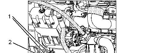
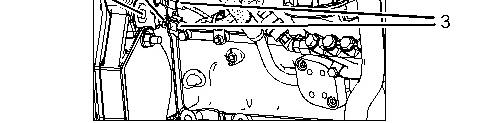
Illustration 1 g01155038
1. Disconnect harness assemblies (3).
2. Remove bolt (2).
3. Remove speed/timing sensors (1).
4. Remove the O-ring seals from speed/timing sensors (1).
Installation Procedure
NOTICE
Keep all parts clean from contaminants.
Contaminants may cause rapid wear and shortened component life.
Note: The speed/timing sensors must be replaced as a pair.
Illustration 2 g01155038
1. Install new O-ring seals on speed/timing sensors (1).
2. Apply clean engine oil to the O-ring seals prior to installation.
3. Position speed/timing sensors (1) on the engine.
Note: Ensure that the speed/timing sensors are seated on the sensor flanges before you tighten the bolt on the bracket.
4. Install bolt (2) and tighten to a torque of 28 ± 7 N·m (21 ± 5 lb ft).
5. Connect harness assemblies (3).
Product: EXCAVATOR
Model: 325D EXCAVATOR GPB
Configuration: 325D L & LN Excavator GPB00001-UP (MACHINE) POWERED BY C7 Engine
Disassembly and Assembly
C7 Engines for Caterpillar Built Machines
Media Number -RENR9218-14
Injection Actuation Pressure Sensor - Remove and Install
SMCS - 1925-010
Removal Procedure
NOTICE
Care must be taken to ensure that fluids are contained during performance of inspection, maintenance, testing, adjusting, and repair of the product. Be prepared to collect the fluid with suitable containers before opening any compartment or disassembling any component containing fluids.
Refer to Special Publication, PERJ1017, "Dealer Service Tool Catalog" for tools and supplies suitable to collect and contain fluids on Cat® products.
Dispose of all fluids according to local regulations and mandates.
NOTICE
Keep all parts clean from contaminants.
Contaminants may cause rapid wear and shortened component life.
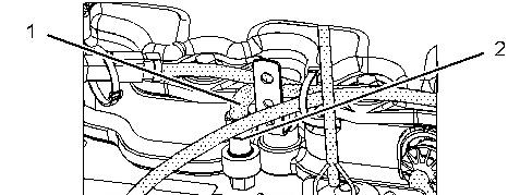
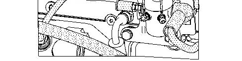
Illustration 1 g01154995
1. Disconnect harness assembly (1).
2. Remove injection actuation pressure sensor (2).
3. Remove the O-ring seal from injection actuation pressure sensor (2).
Installation Procedure
NOTICE
Keep all parts clean from contaminants.
Contaminants may cause rapid wear and shortened component life.
Illustration 2 g01154995
1. Install a new O-ring seal on injection actuation pressure sensor (2).
2. Install injection actuation pressure sensor (2) and tighten to a torque of 20 ± 2 N·m (15 ± 1 lb ft).
3. Connect harness assembly (1).
Product: EXCAVATOR
Model: 325D EXCAVATOR GPB
Configuration: 325D L & LN Excavator GPB00001-UP (MACHINE) POWERED BY C7 Engine
Disassembly and Assembly
C7 Engines for Caterpillar Built Machines
Media Number -RENR9218-14
Fuel Pressure Sensor - Remove and Install
SMCS - 7414-010
Removal Procedure
NOTICE
Care must be taken to ensure that fluids are contained during performance of inspection, maintenance, testing, adjusting, and repair of the product. Be prepared to collect the fluid with suitable containers before opening any compartment or disassembling any component containing fluids.
Refer to Special Publication, PERJ1017, "Dealer Service Tool Catalog" for tools and supplies suitable to collect and contain fluids on Cat® products.
Dispose of all fluids according to local regulations and mandates.
NOTICE
Keep all parts clean from contaminants.
Contaminants may cause rapid wear and shortened component life.
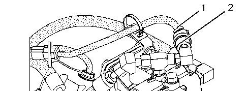
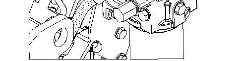
Illustration 1 g01155139
1. Disconnect harness assembly (1).
2. Remove fuel pressure sensor (2) from the fuel filter base.
3. Remove the O-ring seal from fuel pressure sensor (2).
Installation Procedure NOTICE
Keep all parts clean from contaminants.
Contaminants may cause rapid wear and shortened component life.
This is the sample of the manual click on the download link for complete manual
DOWNLOAD LINK
For some reason if link does not work download this pdf and then click