


Note: Use Bookmarks panel to navigate

Product: EXCAVATOR
Model: 325D L EXCAVATOR MCL
Configuration: 325D L Excavator MCL00001-UP (MACHINE) POWERED BY C-7 Engine
Disassembly and Assembly
324D, 325D, 326D and 329D Excavators and 329D MHPU Mobile Hydraulic Power Unit C7 Engine Supplement
Flywheel Housing - Remove and Install
SMCS - 1157-010
Removal Procedure
Start By:
A. Remove the engine. Refer to Disassembly and Assembly, "Engine - Remove".
i02438092
B. Remove the electric starting motor. Refer to Disassembly and Assembly, "Electric Starting Motor - Remove and Install".
C. Remove the flywheel. Refer to Disassembly and Assembly, "Flywheel - Remove and Install".
NOTICE
Keep all parts clean from contaminants.
Contaminants may cause rapid wear and shortened component life.
Note: Cleanliness is an important factor. Before the removal procedure, the exterior of the component should be thoroughly cleaned. This will help to prevent dirt from entering the internal mechanism.
1. Position the engine on suitable blocking.
This is the sample of the manual click on the download link for complete manual
DOWNLOAD LINK
For some reason if link does not work download this pdf and then click
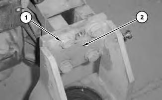
Illustration 1 g01218307
2. Remove bolts (1). Remove bracket assembly (2) .
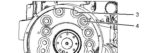
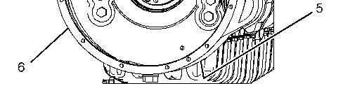
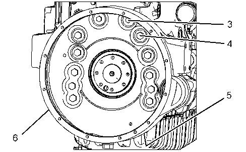
Illustration 2 g01218315
3. Remove bolts (3) and remove bolts (4). Remove bolts (5) that fasten the engine oil pan to the flywheel housing. Use two people in order to remove flywheel housing (6). The weight of flywheel housing (6) is approximately 34 kg (75 lb). Installation Procedure
Note: Cleanliness is an important factor. Before the installation procedure, the exterior of the component should be thoroughly cleaned. This will help to prevent dirt from entering the internal mechanism.
3
1. Clean the rear face of the cylinder block and the mating face of flywheel housing (6). Inspect the crankshaft rear seal for leaks. Inspect the dowels for damage. If the crankshaft rear seal or the dowels are damaged, use new parts for replacement.
2. Apply a continuous bead of Tooling (A) to the rear face of the cylinder block around the mating surface of the crankshaft rear seal and around the rear core plug for the camshaft.
3. Use two people in order to position flywheel housing (6) on the dowels that are located on the engine block. Install bolts (5), bolts (4), and bolts (3) .
4
4. Position bracket (1) and install bolts (2). Repeat for the opposite side of the flywheel housing.
End By:
a. Install the flywheel. Refer to Disassembly and Assembly, "Flywheel - Install".
b. Install the electric starting motor. Refer to Disassembly and Assembly, "Electric Starting Motor - Remove and Install".
c. Install the engine. Refer to Disassembly and Assembly, "Engine - Install".
1993 - 2024 Caterpillar Inc.
Network For SIS Licensees.
Product: EXCAVATOR
Model: 325D L EXCAVATOR MCL
Configuration: 325D L Excavator MCL00001-UP (MACHINE) POWERED BY C-7 Engine
Disassembly and Assembly
324D, 325D, 326D and 329D Excavators and 329D MHPU Mobile Hydraulic Power Unit C7 Engine Supplement
Flywheel - Remove and Install
SMCS - 1156-010
Removal Procedure
Table 1
Required Tools
i02447364
Illustration 1 g01152630
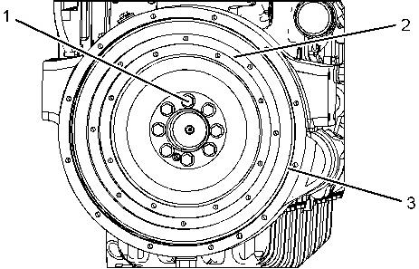
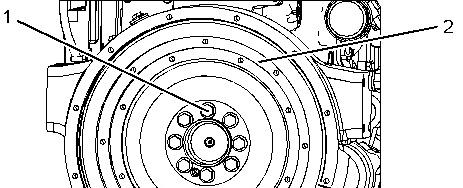
1. Attach Tooling (A) and a suitable lifting device to flywheel (2). The weight of flywheel (2) is approximately 27 kg (60 lb).
2. Remove top bolt (1). Install Tooling (B). Remove remaining bolts (1)
3. Remove flywheel (2) from Tooling (B).
4. Replace ring gear (3), if necessary. Use a hammer and a punch in order to remove the flywheel ring gear.
Installation Procedure Table 2
1. Raise the temperature of ring gear (3)
Note: Do not use a torch to heat the ring gear.
2. Position ring gear (3) on flywheel (2) with the part number toward the crankshaft. Use a soft hammer in order to seat the ring gear against the shoulder of the flywheel. Allow the ring gear to cool.
3. Install Tooling (B) in the crankshaft.
4. Attach Tooling (A) and a suitable lifting device to flywheel (2). The weight of flywheel (2) is approximately 27 kg (60 lb).
5. Position flywheel (2) on Tooling (B) .
6. Apply Tooling (C) to the threads of bolts (1) .
7. Install bolts (1). Remove Tooling (B) and install remaining bolt (1) .
8. Check the flywheel runout. Refer to Testing and Adjusting, "Flywheel - Inspect". Copyright 1993 - 2024 Caterpillar Inc.
Rights Reserved.
Network For SIS Licensees.
Product: EXCAVATOR
Model: 325D L EXCAVATOR MCL
Configuration: 325D L Excavator MCL00001-UP (MACHINE) POWERED BY C-7 Engine
Disassembly and Assembly
324D, 325D, 326D and 329D Excavators and 329D MHPU Mobile Hydraulic Power Unit C7 Engine Supplement
Engine - Install
SMCS - 1000-012
Installation Procedure
Table 1
Required Tools
Tool Part Number Part Description
A 1U-9200 Lever Puller Hoist 2
B 138-7573 Link Brackets 2
C 208-5040 Support Tube 1
D 189-0408 Shackle As 1
NOTICE
Keep all parts clean from contaminants.
Contamination of the hydraulic system with foreign material will reduce the service life of the hydraulic system components.
To prevent contaminants from entering the hydraulic system, always plug or cap the lines, fittings, or hoses as they are disconnected. Cover any disassembled components and clean them properly before assembly.
Clean the hydraulic system properly after any major component exchange or especially after a component failure, to remove any contamination.
NOTICE
Care must be taken to ensure that fluids are contained during performance of inspection, maintenance, testing, adjusting and repair of the product. Be prepared to collect the fluid with suitable containers before opening any compartment or disassembling any component containing fluids.
Refer to Special Publication, NENG2500, "Caterpillar Dealer Service Tool Catalog" for tools and supplies suitable to collect and contain fluids on Caterpillar products.
Dispose of all fluids according to local regulations and mandates.
Note: Visually inspect the condition of the front and rear rubber engine mounts. If the mounts are worn or damaged, use new parts for replacement. If the mounts are compressed, use new parts for replacement.
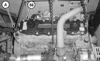
1. Attach Tooling (A) and a suitable lifting device to engine assembly (56), as shown. Install engine assembly (56). The weight of engine assembly (56) is approximately 817 kg (1800 lb).
2
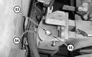
2. Install washer (55). Install mount (54). Install bolts (53). Tighten bolts (53) to a torque of 530 ± 70 N·m (391 ± 52 lb ft).
3
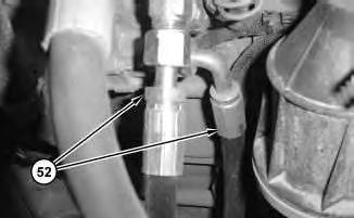
Connect hose assemblies (52) .
4
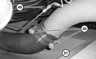
4. Connect tube assembly (49). Tighten clamps (50) to a torque of 11 ± 1 N·m (97 ± 9 lb in).
Connect hose (51) .
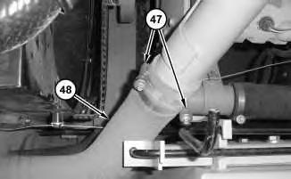
Illustration 5
g01274798
5. Connect hose (48). Tighten clamps (47) to a torque of 11 ± 1 N·m (97 ± 9 lb in).
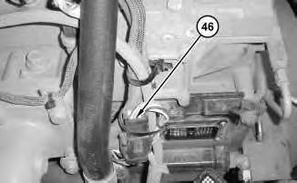
Illustration 6
6. Connect harness assembly (46) .
g01274796
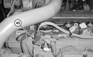
Illustration 7
7. Connect harness assembly (45) .
g01274794
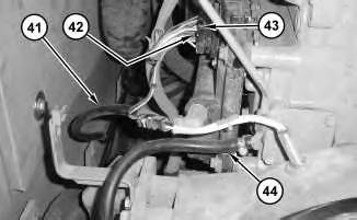
Illustration 8
g01219446
8. Connect hose (44). Connect harness assembly (43) and tighten bolt (42) to a torque of 6 ± 1 N·m (53 ± 9 lb in). Connect hose assembly (41) .
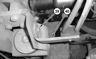
9
g01219433
9. Position bracket (40) and install bolt (39) .
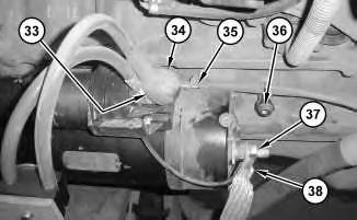
10. Connect ground strap (38). Install nut (37) and tighten nut (37) to a torque of 31 ± 4 N·m (23 ± 3 lb ft). Install bolt (36). Connect harness assembly (35). Install cable assemblies (34). Install nut (33) and tighten nut (33) to a torque of 31 ± 4 N·m (23 ± 3 lb ft).
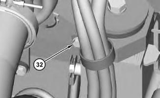
11. Install bolt (32) .
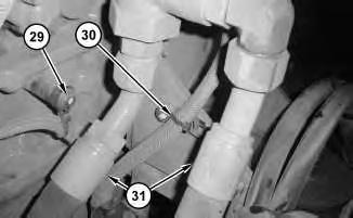
Illustration 12
12. Connect hose assemblies (31). Install cable strap (30). Install bolt (29) .
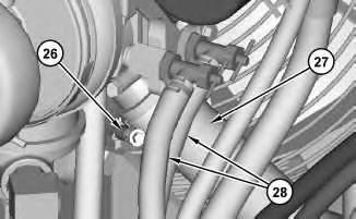
Illustration 13
g01219379
13. Connect hose assemblies (28). Connect hose (27). Tighten clamp (26) to a torque of 11 ± 1 N·m (97 ± 9 lb in).
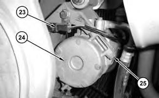
Illustration 14
g01219316
14. Position compressor assembly (24). Install bolts (25). Connect harness assembly (23).
15
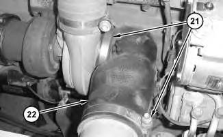
15. Connect hose (22). Tighten clamps (21) to a torque of 11 ± 1 N·m (97 ± 9 lb in).
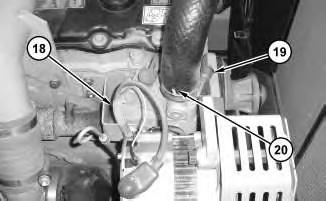
Illustration 16
16. Connect hose (20). Tighten clamp (19) to a torque of 11 ± 1 N·m (97 ± 9 lb in). Connect harness assembly (18) .
17
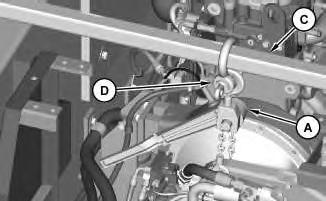
Illustration 18
g01219300
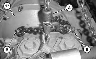
17. Attach Tooling (A), Tooling (B), Tooling (C), and Tooling (D) to main hydraulic pump (17). The weight of main hydraulic pump (17) is approximately 272 kg (600 lb).
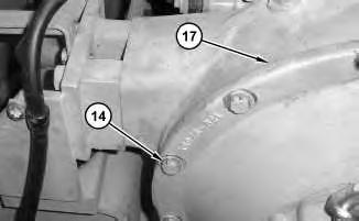
Illustration 19
18. Position main hydraulic pump (17) onto the flywheel housing. Install nine of bolts (14) .
20
21
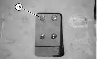
22
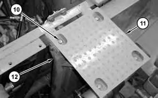
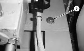
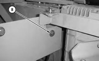
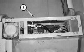
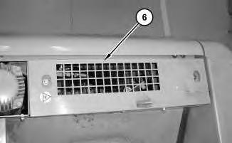
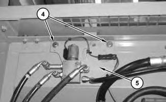
Illustration 28
25. Position bracket assembly (5) and install bolts (4) .
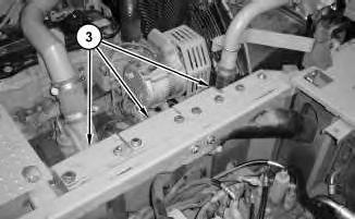
Illustration 29
26. Install sheet assemblies (3) .
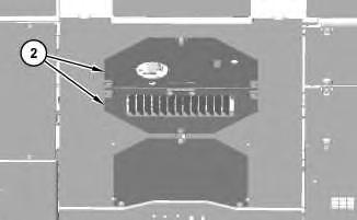
Illustration 30
27. Install plate assemblies (2) .
g01219122
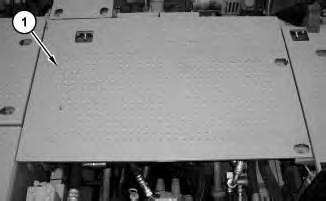
28. Install sheet assembly (1) .
29. Install the belt. Refer to Operation and Maintenance Manual, "BeltInspect/Adjust/Replace".
30. Fill the coolant system. Refer to Operation and Maintenance Manual, "Cooling System Coolant (ELC) - Change" and Operation and Maintenance Manual, "Capacities (Refill)" for the machine that is being serviced.
End By:
a. Install the fan. Refer to Disassembly and Assembly, "Fan - Remove and Install".
b. Install the fan guard. Refer to Disassembly and Assembly, "Fan Guard - Remove and Install".
c. Install the muffler. Refer to Disassembly and Assembly, "Muffler - Remove and Install".
d. Install the hood. Refer to Disassembly and Assembly, "Hood - Remove and Install".
Product: EXCAVATOR
Model: 325D L EXCAVATOR MCL
Configuration: 325D L Excavator MCL00001-UP (MACHINE) POWERED BY C-7 Engine
Disassembly and Assembly
324D, 325D, 326D and 329D Excavators and 329D MHPU Mobile Hydraulic Power Unit C7 Engine Supplement
i02544238
Engine - Remove
SMCS - 1000-011
Removal Procedure
Table 1
Required Tools
Tool Part Number Part Description Qty
A 1U-9200 Lever Puller Hoist 2
B 138-7573 Link Bracket 2
C 208-5040 Support Tube 1
D 189-0408 Shackle As 1
Start By:
a. Release the hydraulic system pressure. Refer to Disassembly and Assembly, "Hydraulic System Pressure - Release".
b. Remove the hood. Refer to Disassembly and Assembly, "Hood - Remove and Install".
c. Remove the muffler. Refer to Disassembly and Assembly, "Muffler - Remove and Install".
d. Remove the fan guard. Refer to Disassembly and Assembly, "Fan Guard - Remove and Install".
e. Remove the fan. Refer to Disassembly and Assembly, "Fan - Remove and Install".
Note: Put identification marks on all hoses, on all hose assemblies, on all wires, and on all tube assemblies for installation purposes. Plug all hose assemblies and all tube assemblies. This helps to prevent fluid loss, and this helps to keep contaminants from entering the system.
NOTICE
Keep all parts clean from contaminants.
Contamination of the hydraulic system with foreign material will reduce the service life of the hydraulic system components.
To prevent contaminants from entering the hydraulic system, always plug or cap the lines, fittings, or hoses as they are disconnected. Cover any disassembled components and clean them properly before assembly.
Clean the hydraulic system properly after any major component exchange or especially after a component failure, to remove any contamination.
NOTICE
Care must be taken to ensure that fluids are contained during performance of inspection, maintenance, testing, adjusting, and repair of the product. Be prepared to collect the fluid with suitable containers before opening any compartment or disassembling any component containing fluids.
Refer to Special Publication, NENG2500, "Dealer Service Tool Catalog" for tools and supplies suitable to collect and contain fluids on Cat products.
Dispose of all fluids according to local regulations and mandates.
At operating temperature, the hydraulic oil is hot and under pressure. Hot oils can cause burns.
To prevent possible personal injury, release the pressure in the work tool hydraulic circuit (boom, stick, bucket, and swing), travel circuits, and the hydraulic oil tank at the filler cap before any hydraulic lines or components are disconnected or removed.
Remove the filler cap only when the engine is stopped and the filler cap is cool enough to touch.
1. Drain the coolant from the cooling system into a suitable container for storage or for disposal. Refer to Operation and Maintenance Manual, "Cooling System Coolant (ELC)Change" for the machine that is being serviced.
2. Remove the belt. Refer to Operation and Maintenance Manual, "BeltInspect/Adjust/Replace".
2
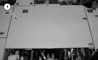
4. Remove plate assemblies (2).
Illustration 3
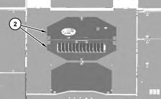
5. Remove sheet assemblies (3).
4
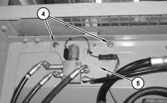
6. Remove bolts (4). Position bracket assembly (5) out of the way.
5
7. Remove cover assembly (6).
6
This is the sample of the manual click on the download link for complete manual
DOWNLOAD LINK
For some reason if link does not work download this pdf and then click