
325 L EXCAVATOR

Note: Use Bookmarks panel to navigate

Product: EXCAVATOR
Model: 325 L EXCAVATOR 2SL
Configuration: 325, 325 L AND 325 LN EXCAVATORS 2SL00001-UP (MACHINE) POWERED BY 3116 ENGINE
Disassembly and Assembly
Air Conditioning and Heating R-12 All Caterpillar Machines
Media Number -SENR3334-02
Publication Date -01/08/2002
General Information
SMCS - 1808; 7309
Date Updated -23/08/2002
Personal injury can result from contact with refrigerant.
This system is under pressure at all times, even if the engine is not running. Heat should never be applied to a charged system.
Contact with refrigerant can cause frost bite. Keep face and hands away to help prevent injury.
Protective goggles must always be worn when refrigerant lines are opened, even if the gauges indicate the system is empty of refrigerant.
Always use caution when a fitting is removed. Slowly loosen the fitting. If the system is still under pressure, evacuate the system recovering the refrigerant before removing the fitting.
Personal injury or death can result from inhaling refrigerant through a lit cigarette.
Inhaling air conditioner refrigerant gas through a lit cigarette or other smoking method or inhaling fumes released from a flame contacting air conditioner refrigerant gas, can cause bodily harm or death.
Do not smoke when servicing air conditioners or wherever refrigerant gas may be present.
Before any checks of the air conditioning and heating system are made, move the machine to a smooth horizontal surface. Lower all implements to the ground. Make sure the transmission is in neutral or park and that
i01790828
the parking brake is engaged. Keep all other personnel away from the machine or where they can be seen.
• All refrigerant lines that are metal or flexible hose must be free of sharp bends. Also, do not use a refrigerant line that is kinked. Sharp bends will cause a restriction in the refrigerant flow. Restrictions in the refrigerant lines are identified by cold spots or frost on the line at the location of the restriction. Restrictions in the lines reduce the performance and the efficiency of the system.
• The radius of bends in the flexible hose must never be less than 10 times the outside diameter of the hose.
• Do not allow the flexible hoses to come within 63.5 mm (2.50 inch) of the exhaust manifold.
• The hoses need to be inspected yearly for leaks and for hardness. Conduct a leak test on all the hoses and the lines. Refer to the Service Manual, SENR3334, "Refrigerant LeakageTest" section in testing and adjusting. Replace hoses if leaks or hardness are in the hoses. Replace hoses with new hose that is sealed and free of contaminants.
• The correct use of wrenches is very important when connections are made. The type of wrench that is used is also important. Only use wrenches that are made for use with tube type fittings. When a hose is connected or disconnected from the system, use a wrench on the fitting and use a wrench on the nut. When a metal line is connected or disconnected from the system, use a wrench on the fitting and use a wrench on the nut.
• Install protective plugs or protective caps on all components and hoses that are disconnected or removed.
• O-ring seals and O-ring seats must be in good condition. Small cuts, scratches, or particles of dirt will cause a leak in the system. Put new refrigerant oil on all new O-ring seals at the time of installation. Do not use any kind of sealant on connections.
• Dust caps on the compressor block fittings are the primary seals on the air conditioning system.
• All machines should have an identification tag that specifies the refrigerant charge for the machine. The tag should be located in the operator compartment.
• If water is in the vents check the nonreturn valve. If water leaks from the air conditioning system, check the nonreturn valve. The nonreturn valve should have the proper position and the proper direction.
• If engine coolant is leaking into the operator compartment, check for loose clamps on the heater hoses.
Copyright 1993 - 2025 Caterpillar Inc.
Rights Reserved.
Network For SIS
Thu Apr 3 15:19:57 UTC+0530 2025
This is the sample of the manual click on the download link for complete manual
For some reason if link does not work download this pdf and then click
Product: EXCAVATOR
Model: 325 L EXCAVATOR 2SL
Configuration: 325, 325 L AND 325 LN EXCAVATORS 2SL00001-UP (MACHINE) POWERED BY 3116 ENGINE
Disassembly and Assembly
Air Conditioning and Heating R-12 All Caterpillar Machines
Media Number -SENR3334-02
Publication Date -01/08/2002
Date Updated -23/08/2002
In-Line Refrigerant Dryer - Remove and Install
SMCS - 7322-010
i01790844
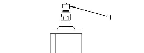
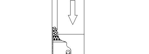
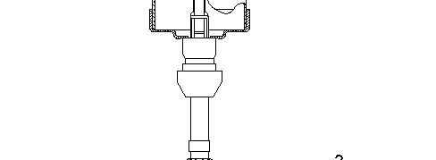

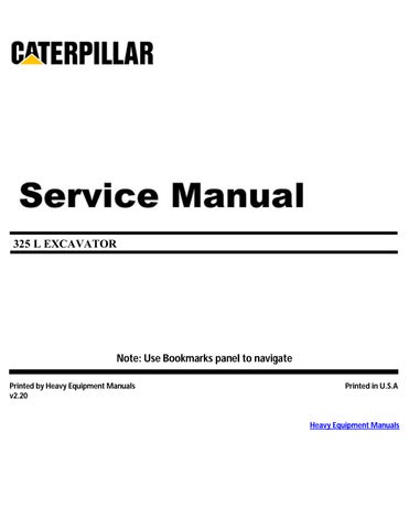
Illustration 1 g00654556
Typical In-Line Dryer
(1) Inlet hose with air conditioner quick disconnects
(2) Outlet hose with air conditioner quick disconnects
In order to replace the in-line dryer and the orifice tube that is in the in-line dryer, use the procedure that follows.
Before any service work is performed on the air conditioning system, refer to the Service Manual, SENR3334, "Machine Preparation for Troubleshooting" section in Testing and Adjusting.
1. Stop the engine for five minutes in order to equalize the pressure in the air conditioning system.
2. Disconnect the inlet hose (1) from the old in-line dryer.
3. Connect the inlet hose that was disconnected in Step 2 to the inlet on the new in-line dryer.
4. Start the engine and operate the air conditioning system.
5. With the air conditioning system in operation, disconnect the outlet hose (2) from the old inline dryer.
6. Stop the engine for five minutes in order to equalize the pressure in the air conditioning system.
7. Connect the outlet hose (2) that was disconnected in Step 5 to the outlet on the new in-line dryer.
Note: Do not add oil to the in-line dryer. Copyright 1993 - 2025 Caterpillar Inc.
Network For SIS Licensees. Thu Apr 3 15:20:58 UTC+0530 2025
Product: EXCAVATOR
Model: 325 L EXCAVATOR 2SL
Configuration: 325, 325 L AND 325 LN EXCAVATORS 2SL00001-UP (MACHINE) POWERED BY 3116 ENGINE
Disassembly and Assembly
Air Conditioning and Heating R-12 All Caterpillar Machines
Media Number -SENR3334-02
Publication Date -01/08/2002 Date Updated -23/08/2002
Machine Preparation for Disassembly and Assembly
SMCS - 7320-017
Personal injury can result from contact with refrigerant.
This system is under pressure at all times, even if the engine is not running. Heat should never be applied to a charged system.
Contact with refrigerant can cause frost bite. Keep face and hands away to help prevent injury.
Protective goggles must always be worn when refrigerant lines are opened, even if the gauges indicate the system is empty of refrigerant.
Always use caution when a fitting is removed. Slowly loosen the fitting. If the system is still under pressure, evacuate the system recovering the refrigerant before removing the fitting.
Personal injury or death can result from inhaling refrigerant through a lit cigarette.
Inhaling air conditioner refrigerant gas through a lit cigarette or other smoking method or inhaling fumes released from a flame contacting air conditioner refrigerant gas, can cause bodily harm or death.
Do not smoke when servicing air conditioners or wherever refrigerant gas may be present.
Before any checks of the air conditioning and heating system are made, move the machine to a smooth horizontal surface. Lower all implements to the ground. Make sure the transmission is in neutral or park and that
i01790494
the parking brake is engaged. Keep all other personnel away from the machine or where they can be seen.
When the service work is done on the air conditioning system, it is important to keep the system clean and free from contamination. Plugs and caps must be used in order to close the components and hoses when the components and hoses are open. The plugs and caps protect the system from dirt and air (moisture). Only new refrigerant oil of the correct viscosity and new refrigerant can be added to the system. Refer to the Service Manual, SENR3334, "Refrigerant Compressor" section in this manual for the correct oil. Any other material or any other substance is considered noncondensable and the material will contaminate the system. Keep the work area clean.
• Dust caps on the refrigerant compressor block fitting are the primary seal on the air conditioning system.
• All machines should have an identification tag in the cab that specifies the proper refrigerant charge for the machine.
When replacement or repair of components and hoses are required, perform the following procedure:
1. Remove the refrigerant charge. Refer to the Service Manual, SENR3334, "Refrigerant Recovery" section in Testing and Adjusting.
2. Remove the component or remove the hose that is being repaired or replaced. Install protective plugs on components or hoses that are left exposed to the air.
3. Replace any damaged component or hose.
4. Use the following table in order to determine the amount of oil that is lost during individual replacements of components. Add the correct amount of oil to the compressor before the system is evacuated. No additional oil should be added to the system if the compressor is replaced at the same time as other components in the system.
Oil Capacities for Component Replacements
Accumulator
30 mL (1 fl oz)
Compressor Refer to the Service Manual, SENR3334, "Refrigerant Compressor Oil -Check" section in Testing and Adjusting.
Condenser
Evaporator
In-Line Dryer (1)
Receiver-Dryer
30 mL (1 fl oz)
90 mL (3 fl oz)
30 mL (1 fl oz)
30 mL (1 fl oz)
Table 1
( 1 ) Refer to the Service Manual, SENR3334, "In-Line-Refrigerant Dryer - Remove and Install " before any oil is added.
5. Refer to the Service Manual, SENR3334, "Refrigerant System-Evacuate" section in testing and adjusting.
6. Refer to the Service Manual, SENR3334, "Refrigerant System-Charge" section in Testing and Adjusting.
Product: EXCAVATOR
Model: 325 L EXCAVATOR 2SL
Configuration: 325, 325 L AND 325 LN EXCAVATORS 2SL00001-UP (MACHINE) POWERED BY 3116 ENGINE
Disassembly and Assembly
Air Conditioning and Heating R-12 All Caterpillar Machines
Media Number -SENR3334-02
Publication Date -01/08/2002
Receiver-Dryer - Remove and Install
SMCS - 7322-010
Date Updated -23/08/2002
i01790843
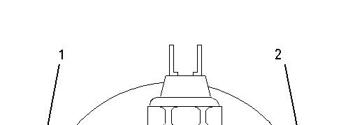
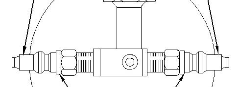

Illustration 1 g00382493
Top View of Receiver-Dryer
(1) Inlet
(2) Outlet
(3) Quick Disconnect Fittings
NOTICE
If the receiver-dryer does not have air conditioner quick disconnects, the system must be completely recovered, evacuated, and recharged after the receiver-dryer has been replaced.
The refrigerant that is in the system must be recovered if the receiver-dryer does not have air conditioner quick disconnects (3). Refer to the Service Manual, SENR3334, "Refrigerant Recovery" section in Testing and Adjusting before you remove the receiver-dryer. If the receiverdryer has air conditioner quick disconnects (3) use the procedure that follows.
Refer to Safety Requirements before service is performed on the air conditioning system.
1. Stop the engine for five minutes. This allows the air conditioning system to equalize the pressure.
2. Disconnect the inlet hose (1) from the old receiver-dryer at the air conditioner quick disconnects.
3. Connect the hose that was disconnected in Step 2 to the inlet on the new receiver-dryer.
4. Disconnect the electrical connections on the old receiver-dryer. Connect the electrical connections to the new receiver-dryer.
5. Add 30 mL (1 fl oz) of refrigerant oil to the system.
Note: Do not add refrigerant oil if the compressor was changed also.
6. Start the engine. Operate the air conditioning system for one minute.
7. With the air conditioning system in operation, disconnect the outlet hose (2) from the old receiver-dryer. Disconnect the old receiver-dryer at the air conditioner quick disconnects.
8. Stop the engine for five minutes. This allows the air conditioning system to equalize pressure.
9. Connect the outlet hose (2) that was disconnected in step 6 to the new receiver-dryer.
Thu Apr 3 15:20:43 UTC+0530 2025
Product: EXCAVATOR
Model: 325 L EXCAVATOR 2SL
Configuration: 325, 325 L AND 325 LN EXCAVATORS 2SL00001-UP (MACHINE) POWERED BY 3116 ENGINE
Disassembly and Assembly
Air Conditioning and Heating R-12 All Caterpillar Machines
Media Number -SENR3334-02
Publication Date -01/08/2002
Refrigerant Accumulator - Remove and Install
SMCS - 1808-010; 7320-010
Date Updated -23/08/2002
The refrigerant must be recovered before the accumulator is removed. Refer to the Service Manual, SENR3334, "Refrigerant Recovery" section in Testing and Adjusting.
Refer to the Service Manual, SENR3334, "Machine Preparation for troubleshooting" section in Testing and Adjusting before service work is performed.
Remove the accumulator. The accumulator has an internal oil drain hole which could become plugged. The oil could be trapped inside the accumulator. It is necessary to check for excessive oil when the accumulator is changed. Add the same amount of oil that was drained from the old accumulator. Add an additional 30 mL (1 fl oz) to the new accumulator before the new accumulator is installed. Do not add oil if the compressor was changed also. Evacuate the system and recharge the system. Refer to the Service Manual, SENR3334, "Refrigerant SystemEvacuate" section in Testing and Adjusting. Refer to the Service Manual, SENR3334, "Refrigerant System - Charge" section in Testing and Adjusting.
Note: If the accumulator has frost on the outside, the air conditioning system still contains refrigerant.
Copyright 1993 - 2025 Caterpillar Inc. All Rights Reserved. Private Network For SIS Licensees. Thu Apr 3 15:20:23 UTC+0530 2025
i01790836
Product: EXCAVATOR
Model: 325 L EXCAVATOR 2SL
Configuration: 325, 325 L AND 325 LN EXCAVATORS 2SL00001-UP (MACHINE) POWERED BY 3116 ENGINE
Disassembly and Assembly
Air Conditioning and Heating R-12 All Caterpillar Machines
Media Number -SENR3334-02
Publication Date -01/08/2002
Refrigerant Compressor - Remove and Install
SMCS - 1802-010 Removal
Date Updated -23/08/2002
i01790832
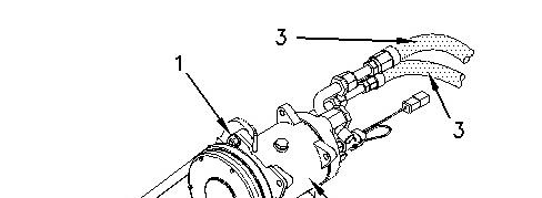

Illustration 1 g00742981
(1) Bolt
(2) Drive belt
(3) Suction and discharge hoses
(4) Compressor
1. Remove the refrigerant charge. Refer to the Service Manual, SENR3334, "Refrigerant Recovery" section in Testing and Adjusting.
2. Disconnect electrical wires from the magnetic clutch.
3. Loosen all the mounting bolts and loosen the belt tightener (if equipped). Remove drive belt (2) .
4. Disconnect hoses (3) and put plugs or caps on the hoses. Put plugs or caps on the fittings of the compressor. Put identification marks on the hoses. The marks will ensure that the hoses will be connected correctly at a later time.
5. Remove all the mounting bolts and remove the compressor (4). The weight of the compressor is approximately 18 kg (40 lb).
Installation
1. Check the amount and condition of the oil in the compressor (4). Refer to the Service Manual, SENR3334, "Refrigerant Compressor Oil-Test" section in Testing and Adjusting.
2. Inspect the drive belt (2). If the drive belt (2) is damaged or worn replace the belt.
3. Install the compressor (4). Do not tighten the mounting bolts until drive belt (2) is installed and adjusted.
4. Connect the discharge and the suction hoses (3) to the discharge and suction ports on the compressor.
5. Connect the electrical wires to the magnetic clutch.
6. Evacuate the system. Refer to the Service Manual, SENR3334, "Refrigerant SystemEvacuate" section in Testing and Adjusting.
7. Charge the system. Refer to the Service Manual, SENR3334, "Refrigerant System - Charge" section in Testing and Adjusting.
8. For the correct system operation, refer to the Service Manual, SENR3334, "Troubleshooting Heating and Air Conditioning Control System" section in Testing and Adjusting.
Note: Refer to the Service Manual, SENR3334, "Refrigerant Compressor" in the Specifications Section for the correct belt tension.
Copyright 1993 - 2025 Caterpillar Inc. All Rights Reserved. Private Network For SIS Licensees. Thu Apr 3 15:20:06 UTC+0530 2025
Product: EXCAVATOR
Model: 325 L EXCAVATOR 2SL
Configuration: 325, 325 L AND 325 LN EXCAVATORS 2SL00001-UP (MACHINE) POWERED BY 3116 ENGINE
Disassembly and Assembly
Air Conditioning and Heating R-12 All Caterpillar Machines
Media Number -SENR3334-02 Publication Date -01/08/2002
Date Updated -23/08/2002
Refrigerant Expansion Valve - Remove and Install
SMCS - 7320-010
To replace the expansion valve, use the procedure that follows. Refer to Service Manual, SENR3334, "Troubleshooting Heating and Air Conditioning Control System" before service work is performed on the air conditioning system.
1. Recover the refrigerant.
Note: Cap all disconnected lines and hoses.
2. Remove the insulation and the clip. The insulation and the clip hold the sensing bulb to the evaporator outlet pipe.
3. Disconnect the sensing line for pressure from the evaporator outlet pipe.
4. Loosen and remove the two connections at the expansion valve. Remove the expansion valve.
Note: Check the O-ring seals. The seals must be in good condition and the seals must be properly lubricated with the correct refrigerant oil before assembly.
5. Install the expansion valve for replacement and tighten the two connections.
6. Tighten the pressure sensing connection on the evaporator outlet pipe.
7. Use a 8P-6355 Clip to hold the sensing bulb onto the evaporator outlet pipe. The sensing bulb should be as close to the coil as possible. The bulb should be upstream of the pressure sensing connection on the evaporator outlet pipe. The 5P-7070 Insulation should be wrapped tightly around the clip, the sensing bulb and the outlet pipe. There should be no insulation between the bulb and the outlet pipe.
8. Tighten all the connections correctly.
9. Evacuate the system. Refer to the Service Manual, SENR3334, "Refrigerant SystemEvacuate" section in testing and adjusting.
i01790839
10. Charge the system with the correct amount of refrigerant by weight. Refer to the Service Manual, SENR3334, "Refrigerant System - Charge" section in testing and adjusting.
Copyright 1993 - 2025 Caterpillar Inc. All Rights Reserved. Private Network For SIS Licensees.
Thu Apr 3 15:20:32 UTC+0530 2025
Product: EXCAVATOR
Model: 325 L EXCAVATOR 2SL
Configuration: 325, 325 L AND 325 LN EXCAVATORS 2SL00001-UP (MACHINE) POWERED BY 3116 ENGINE
Disassembly and Assembly
Air Conditioning and Heating R-12 All Caterpillar Machines
Media Number -SENR3334-02
Publication Date -01/08/2002
Refrigerant Orifice Tube - Remove and Install
SMCS - 7320-010
Date Updated -23/08/2002
The orifice tube may be located in the refrigerant line near the evaporator inlet, or in the in-line dryer.
If the orifice tube is located in the refrigerant line near the evaporator inlet use the procedure that follows. If the orifice tube is located in the in-line dryer, refer to Dryer Replacement.
Removing the Orifice Tube
Refer to Safety Requirements before service work is performed on the air conditioning system.
The refrigerant must be recovered before removing the accumulator. Refer to the Service Manual, SENR3334, "Refrigerant Recovery" section in testing and adjusting.
NOTICE
Do not attempt to remove the orifice tube with pliers. Do not twist or rotate the orifice tube in the tube assembly.
i01790846
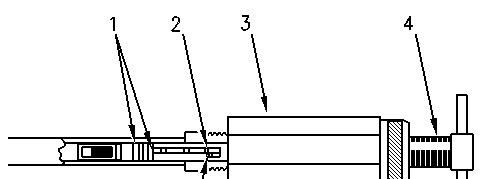

Illustration 1 g00379603
Orifice tube
(1) O-Ring seals
(2) Lugs
(3) Body
(4) Drive screw
(5) Finger lock
1. Disconnect the high side line at the enlarged section of the evaporator inlet port. This will expose the orifice tube for removal.
2. The short prongs on the 208-1375 Orifice Tool Gp must be aligned with the ribs on the orifice tube. Insert the tool onto the tube until the tool bottoms out.
3. Turn drive screw (4) clockwise. Turn far enough to engage the lugs (2) on the orifice tube in the finger lock (5). The finger lock (5) is part of the removal tool.
4. Hold the drive screw (4) stationary. Thread the body (3) forward until the body makes contact with the inlet port.
5. Continue holding the drive screw stationary, and thread the body forward until the orifice tube becomes free.
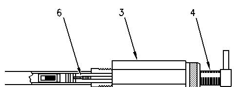

Illustration 2 g00381412
Removing the broken orifice tube
(3) Body
(4) Drive screw
(6) Extractor tip
6. In order to remove the orifice tube assembly, use the extractor tip (6) on 208-1375 Orifice Tool Gp. Insert the tool into the evaporator inlet tube and thread the tool into the brass center of the orifice tube.
7. Repeat steps 3 and 4.
8. If only the brass center of the orifice tube is removed, thread the tool into the plastic body and repeat step 3 and 4.
Orifice Tube Installation
1. Lubricate the O-Ring on the orifice tube with the proper clean refrigerant oil.
2. Place the orifice tube into the 208-1375 Orifice Tool Gp. Insert the orifice tube straight into the evaporator inlet tube without twisting until the tube is seated.
3. Disengage the removal tool from the orifice tube.
4. Use a new O-Ring that is lubricated with clean refrigerant oil. Reconnect the high side line at the enlarged section of the evaporator inlet port.
5. Do a leak test. Evacuate the system and recharge the system. Refer to the Service Manual, SENR3334, "Refrigerant Systems-Evacuate" section in testing and adjusting. Also, refer to the Service Manual, SENR3334, "Refrigerant Systems-Charge" section in testing and adjusting.
Copyright 1993 - 2025 Caterpillar Inc.
Rights Reserved.
Network For SIS Licensees. Thu Apr 3 15:21:08 UTC+0530 2025

Product: EXCAVATOR
Model: 325 L EXCAVATOR 2SL
Configuration: 325, 325 L AND 325 LN EXCAVATORS 2SL00001-UP (MACHINE) POWERED BY 3116 ENGINE
Disassembly and Assembly
37-MT, 41-MT, and 42-MT Series Starting Motors
Media Number -SENR3581-04
General Information
SMCS - 1453
Publication Date -01/10/2008 Date Updated -24/10/2008
i01557321
37-MT and 41-MT Starting Motors
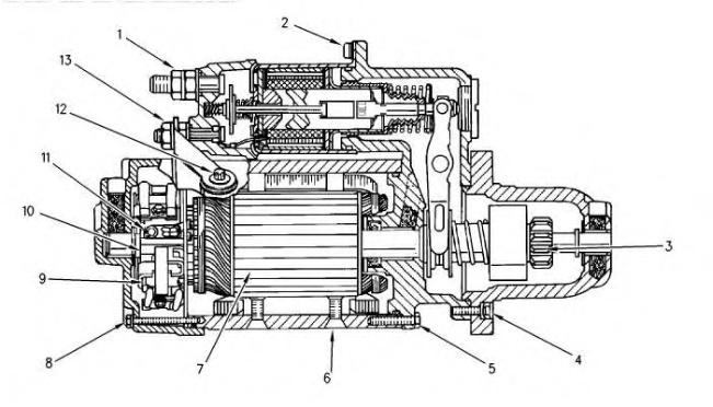
Illustration 1 g00782868
37-MT and 41-MT Cross section view
(1) Nut (Battery)
(2) Solenoid Mounting Screws
(3) Pinion
(4) Pinion Drive Housing Bolts
(5) Shift Lever Housing Bolts
(6) Field Winding Screws
(7) Laminated Core
(8) Rear Housing Bolts
(9) Brush
(10) Commutator
(11) Brush Lead Screws
(12) Motor Terminal Bolt
(13) Motor Terminal Nut
42-MT Starting Motors
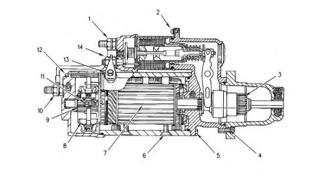
2
42-MT Cross section view
(1) Nut (Battery)
(2) Solenoid Mounting Screws
(3) Pinion
(4) Pinion Drive Housing Bolts
(5) Shift Lever Housing Bolts
Illustration
g00801373
(6) Field Winding Screws
(7) Laminated Core
(8) Brush
(9) Commutator
(10) Ground Terminal Nut
(11) Brush Lead Screws
(12) Rear Housing Bolt
(13) Motor Terminal Bolt
(14) Motor Terminal Nut
1993 - 2025 Caterpillar Inc. All Rights Reserved. Private Network For SIS Licensees. Thu Apr 3 15:17:52 UTC+0530 2025
Product: EXCAVATOR
Model: 325 L EXCAVATOR 2SL
Configuration: 325, 325 L AND 325 LN EXCAVATORS 2SL00001-UP (MACHINE) POWERED BY 3116 ENGINE
Disassembly and Assembly
37-MT, 41-MT, and 42-MT Series Starting Motors
Media Number -SENR3581-04 Publication Date -01/10/2008 Date Updated -24/10/2008
Starting Motor - Assemble - 37-MT and 41-MT
SMCS - 1453-016
Assemble the Starting Motor
Table 1
Required Tools
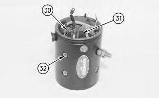
Illustration 1
1. Put SAE 20W oil on all bushings, seals and oil wicks.
i01559761
2. Put field winding coil (29) and pole shoes (30) in position in the starting motor housing. Put 9s-3263 Thread Lock Compound on the threads of screws (31). Tighten to a torque of 20.3 ± 2.3 N·m (179.7 ± 20.4 lb in).
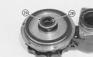
Illustration 2
3. Install bushing (27) and seal (28) into the shift lever housing. Use tool group (B) .
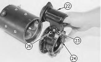
Illustration 3
4. Put the O-ring on the shift lever housing (22) .
5. Install the seals on pin (26). Hold shift lever (24) in shift lever housing (22) and install pin (19) through the housing and lever (24). Install ring (23) with tool (A) .
g00810276
g00810419
This is the sample of the sample click on the download link for complete manual
For some reason if link does not work download this pdf and then click