


This is the sample of the manual click on the download link for complete manual
DOWNLOAD LINK
For some reason if link does not work download this pdf and then click

Product: EXCAVATOR
Model: 323D3 EXCAVATOR FEY
Configuration: 323D3 Excavator FEY00001-UP (MACHINE) POWERED BY C7.1 Engine
Disassembly and Assembly
323D3 Hydraulic Excavators Machine Systems
Media Number -M0092839-01
Date -01/09/2020
Accumulator - Remove and Install
SMCS - 4263-010; 4331-010; 5077-010; 7336-010
Removal Procedure
Start By:
a. Release the system pressure.
Note: The hydraulic accumulator is installed under the main control valve.
NOTICE
Updated -14/09/2020
Care must be taken to ensure that fluids are contained during performance of inspection, maintenance, testing, adjusting, and repair of the product. Be prepared to collect the fluid with suitable containers before opening any compartment or disassembling any component containing fluids.
Refer to Special Publication, NENG2500, "Dealer Service Tool Catalog" for tools and supplies suitable to collect and contain fluids on Cat® products.
Dispose of all fluids according to local regulations and mandates.
Personal injury can result from the sudden release of high pressure oil.
Be sure the engine has been shut off for a minimum of five minutes to ensure that the accumulator pressure is zero.
The accumulator is filled with dry nitrogen. Do not loosen or remove the valve or the cap from the top of the accumulator.
1
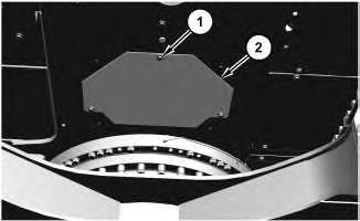
1. Remove bolts (1) and plate (2).
2
Note: Do not release the nitrogen from the hydraulic accumulator unless the unit will be disassembled.
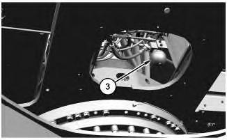
2. Remove hydraulic accumulator (3) by turning the nut that is at the top of the accumulator. Remove the O-ring seal from accumulator (3).
Installation Procedure
3
1. Replace the O-ring seal with a new O-ring seal. Install the O-ring seal in accumulator (3).
2. Install accumulator (3) by tightening the nut that is at the top of the accumulator. Refer to Testing and Adjusting, "Accumulator (Pilot) - Test and Charge" if the accumulator requires charging.
4
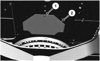
3. Install plate (2) and bolts (1).
4. Check the hydraulic oil level. Refer to Operation and Maintenance Manual, "Hydraulic System Oil Level - Check".
Copyright 1993 - 2024 Caterpillar Inc. All Rights Reserved. Private Network For SIS Licensees. Tue Jul 9 13:27:39 UTC+0530 2024
Product: EXCAVATOR
Model: 323D3 EXCAVATOR FEY
Configuration: 323D3 Excavator FEY00001-UP (MACHINE) POWERED BY C7.1 Engine
Disassembly and Assembly
323D3 Hydraulic Excavators Machine Systems
Media
Boom - Install
SMCS - 6501-012
Installation Procedure Table 1
Note: Make sure that the pin bores in the boom and the pin bores in the upper frame are clean and free of dirt and debris prior to installing the boom in the upper frame.
1. Apply Tooling (E) to the bores in the upper frame and in the bore of the boom.
1
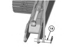
Illustration 2 g06314893
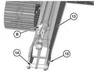
Illustration 3
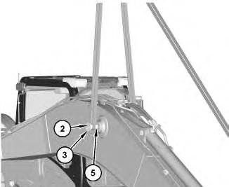
2. Install plate (3) and bolts (2) on each side of pin (5).
3. Attach a suitable lifting device to pin assembly (14). The weight of pin assembly (14) is approximately 28 kg (62 lb). Install pin assembly (14) and install bolt (15).
4. Attach Tooling (B) and a suitable lifting device to boom (13) and pin assembly (14). The combined weight of boom (13) and the stick cylinder is approximately 2038 kg (4493 lb). Position boom (13) onto the machine.
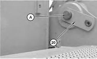
Illustration 4 g06315248
5. Apply Tooling (E) to pin assembly (20). Attach a suitable lifting device to pin assembly (20). The weight of pin assembly (20) is approximately 44 kg (97 lb). Use Tooling (A) and a suitable lifting device to install pin assembly (20).
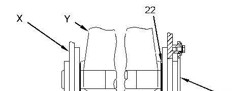
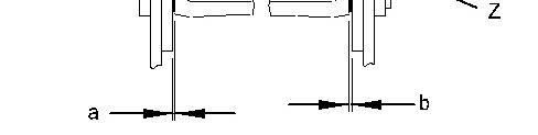
Illustration 5 g06315257
6. Measure the total clearance between the boom and the upper frame at the bore for the boom foot pin assembly. The total clearance of Dimension (a) plus Dimension (b) must not be more than 1.6 mm (0.06 inch). If the total clearance is less than 1.6 mm (0.06 inch), the
addition of shims between the boom and the upper frame will not be required. If the total clearance is more than 1.6 mm (0.06 inch), add the correct thickness of shims to obtain the required clearance.
6
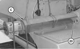
7. If shims (25) need to be installed, attach a suitable lifting device to Tooling (C). The weight of Tooling (C) is approximately 136 kg (300 lb). Attach Tooling (C) to pin assembly (20). Use Tooling (C) to remove pin assembly (20). The combined weight of Tooling (C) and pin assembly (20) is approximately 180 kg (397 lb).
8. Install the correct number of shims. Repeat Step 5 and Step 6.
7
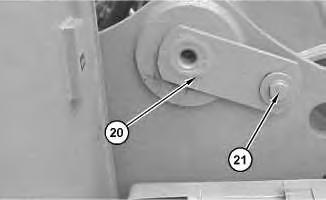
9. Install bolt (21) that retains pin assembly (20).
8
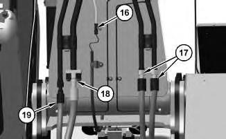
10. Connect harness assembly (16). Connect hose assemblies (17), (18), and (19). Tighten hose assemblies (17) and (19) to a torque of 160 ± 16 N·m (118 ± 12 lb ft).
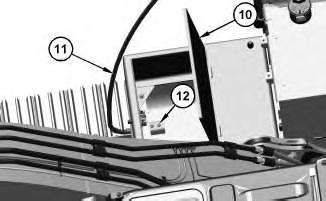
Install handrail (11) and bolts (12). Close cover (10) of the storage box.
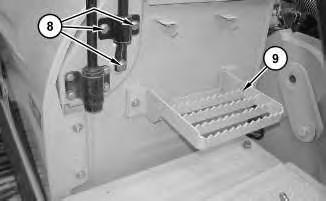
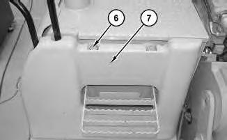
Illustration 11
14. Install cover (7) and bolts (6).
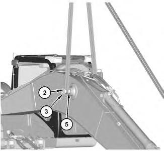
Illustration 12
g06314863
15. Remove bolts (2) and retaining plates (3) from pin (5).
13
g06314822
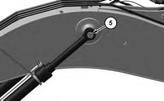
16. Use Tooling (A) to drive pin (5) so that the pin is flush with the boom. Remove Tooling (A) and install Tooling (A) onto the other side of pin (5).
17. Attach a suitable lifting device to boom cylinder (4). The weight of boom cylinder (4) is approximately 290 kg (633 lb). Raise boom cylinder (4) into position. Install any shims that were present. Install Tooling (A) into pin (5). Use a hammer to drive pin (5) into boom cylinder (4). Remove Tooling (A). Repeat for the other boom cylinder (4).
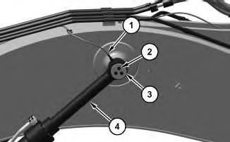
18. Install the spacer and retainer plate (3). Install bolts (2). Repeat for other side.
19. Connect hose assembly (1).
End By:
a. Install the stick.
Tue Jul 9 13:05:31 UTC+0530 2024
Product: EXCAVATOR
Model: 323D3 EXCAVATOR FEY
Configuration: 323D3 Excavator FEY00001-UP (MACHINE) POWERED BY C7.1 Engine
Disassembly and Assembly
323D3 Hydraulic Excavators Machine Systems
Media
Boom - Remove
SMCS - 6501-011
Removal Procedure Table 1
Start By:
a. Remove the
b. Release the
Illustration 1
1. Disconnect hose assembly (1) from boom cylinder (4). Remove bolts (2). Remove retainer plate (3) and the spacer .
Illustration 2
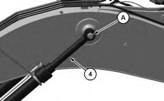
Illustration 3
2. Attach a suitable lifting device to boom cylinder (4). The weight of boom cylinder (4) is approximately 173 kg (381 lb). Install Tooling (A) into pin (5). Use a hammer to drive pin (5) out of boom cylinder (4).
Note: Remove any shims that may be present. Mark the shims for installation purposes.
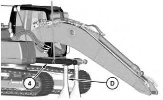
Illustration 4
g06319772
3. Lower boom cylinder (4) onto Tooling (D).
4. Repeat Steps 1 through 3 for the other boom cylinder.
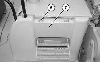
Illustration 5
5. Remove bolts (6). Remove cover (7).
g01212891
Illustration 6
6. Remove three bolts (8). Remove step (9).
g01212899
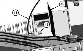
Illustration 7
g06314824
7. Open cover (10) of the storage box. Remove bolts (12) and handrail (11).
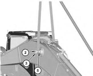
Illustration 8
g06314863
8. Install retainer plate (3) and bolts (2) on each side of pin (5). Attach a suitable lifting device to each side of pin (5).
9
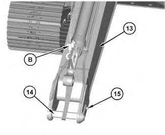
Illustration 10
9. Attach a suitable lifting device to pin assembly (14). The weight of pin assembly (14) is approximately 28 kg (62 lb). Install pin assembly (14) and install bolt (15).
10. Attach Tooling (B) and a suitable lifting device to boom (13) and pin assembly (14). The combined weight of boom (13) and the stick cylinder is approximately 2038 kg (4493 lb). Apply slight lifting tension to boom (13).
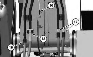
Illustration 11
11. Disconnect harness assembly (16). Disconnect hose assemblies (17), (18), and (19).
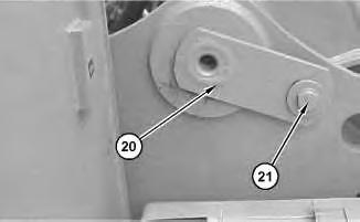
Illustration 12
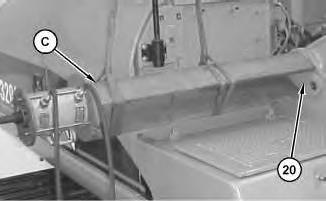
Illustration 13 g06314827
12. Remove bolt (21). Attach a suitable lifting device to Tooling (C). The weight of Tooling (C) is approximately 136 kg (300 lb). Attach Tooling (C) to pin assembly (20). Use Tooling (C) to remove pin assembly (20). The combined weight of Tooling (C) and pin assembly (20) is approximately 180 kg (397 lb).
13. Remove pin assembly (20).
14. Remove the boom. Remove any shims that may be present.
Note: Note the locations of any shims for assembly purposes.
Copyright 1993 - 2024 Caterpillar Inc. All Rights Reserved. Private Network For SIS Licensees. Tue Jul 9 13:01:44 UTC+0530 2024
Product: EXCAVATOR
Model: 323D3 EXCAVATOR FEY
Configuration: 323D3 Excavator FEY00001-UP (MACHINE) POWERED BY C7.1 Engine
Disassembly and Assembly
323D3 Hydraulic Excavators Machine Systems
Boom Bearings and Seals - Remove and Install
SMCS - 6501-010-BD; 6501-010-SA
Removal Procedure Table 1
Required Tools
Start By:
a. Remove the
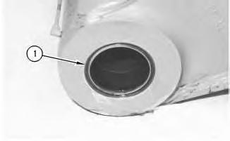
Illustration 1
1. Remove lip seal (1).
g00479266
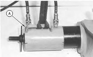
Illustration 2
g00479267
2. Use Tooling (A) to remove the sleeve bearing. Remove the sleeve bearings.
3. Repeat Steps 1 and 2 to remove the lip seal and the sleeve bearing from the other side of the boom.
Installation Procedure
Table 2
Required Tools
Tool Part Number Part Description Qty
B 1P-0520 Bearing and Seal Driver 1
C 452-6006 Molybdenum Grease
1. Make sure that the bores for the sleeve bearings are free of paint and grease prior to the installation of the sleeve bearings. Coat the sleeve bearings and the bearing bores with Tooling (C) prior to the installation of the sleeve bearings in the bores. Sleeve bearings must be installed with the identification numbers toward the outside of the boom.
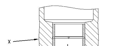

Illustration 3 g00599079 (X) Boom (Y) Bearing
2. Lower the temperature of the sleeve bearings. Use Tooling (B) to install the sleeve bearing in the pin bore at the foot of the boom. Install the sleeve bearing until Dimension (a) is 9.5 ± 0.8 mm (0.37 ± 0.03 inch) below the outside surface of the boom.
Illustration 4
g00479266
3. Apply Tooling (C) to lip seals (1). Use Tooling (B) to install lip seal (1). Install the seal with the sealing lip toward the outside of the boom.
4. Repeat Steps 2 and 3 to install the sleeve bearing and the lip seal on the other side of the boom.
5. Put a thin coat of Tooling (C) on the sleeve bearings. End By:
a. Install the boom.
Product: EXCAVATOR
Model: 323D3 EXCAVATOR FEY
Configuration: 323D3 Excavator FEY00001-UP (MACHINE) POWERED BY C7.1 Engine
Disassembly and Assembly
323D3 Hydraulic Excavators Machine Systems
Media Number -M0092839-01 Publication Date -01/09/2020 Date Updated -14/09/2020
Boom Cylinder - Assemble
SMCS - 5456-016
Assembly Procedure
Table 1
Required Tools Tool
B - Loctite 243 -
Note: Cleanliness is an important factor. Before assembly, all parts should be thoroughly cleaned in cleaning fluid. Allow the parts to air dry. Do not use Wiping cloths or rags to dry parts. Lint may be deposited on the parts which may cause later trouble. Inspect all parts. If any parts are worn or damaged, use new parts for replacement. All disassembly and all assembly procedures must be performed on a clean work surface and in a clean hydraulic area. Keep cleaned parts covered and protected.
Note: Check seals for wear or for damage. Replace seals, if necessary.
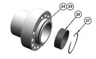
Illustration 1
g06311628
1. Install backup ring (25) and seal (24) onto the head.
2. Install sleeve bearing (26) and ring (27) into the head.
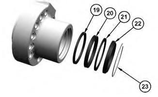
Illustration 2
g06311627
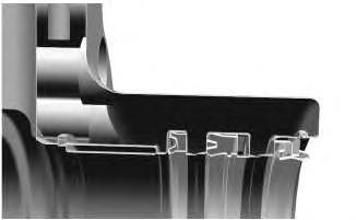
Illustration 3
Orientation of the seals.
g06311095
3. Install seal (19), seal (20), back up ring (21), seal (22), and ring (23) into the head.
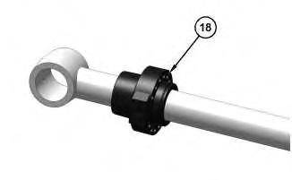
Illustration 4
4. Install head (18).
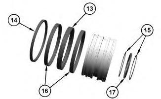
Illustration 5
g06311624
5. Install rings (15) and seal (17) into the piston.
6. Install rings (16), seal assembly (13), and ring (14) onto the piston.
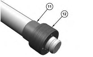
Illustration 6
g06311623
7. Install stopper (11) and piston (12). Tighten piston (12) to a torque of 980 to 1176 N.m (723 to 867 lb ft).
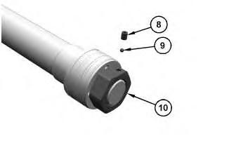
Illustration 7
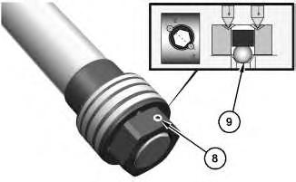
Illustration 8
g06311918
8. Install lock nut (10). Tighten lock nut (10) to a torque of 1862 to 1960 N.m (1373 to 1446 lb ft).
9. Before installing ball (9), form a dimple on the piston rod groove using Tooling (A). Install ball (9).
10. Apply Tooling (B) to the threads of set screw (8). Install set screw (8). Tighten set screw (8) to a torque of 49.0 ± 9.8 N.m (36.1 ± 7.2 lb ft).
11. Stake set screw (8) in two places as shown in Illustration 8.
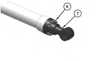
Illustration 9
g06311617
12. Install rod assembly (7) and bolts (6). Tighten bolts (6) to a torque of 333.2 to 352.8 N.m (245.8 to 260.2 lb ft).
This is the sample of the manual click on the download link for complete manual
DOWNLOAD LINK
For some reason if link does not work download this pdf and then click