

Note: Use Bookmarks panel to navigate
This is the sample of the manual click on the download link for complete manual
For some reason if link does not work download this pdf and then click

Product: EXCAVATOR
Model: 320D L EXCAVATOR A8F
Configuration: 320D & 320D L Excavators A8F00001-UP (MACHINE) POWERED BY C6.4 Engine
Disassembly and Assembly
C6.4 Engine for Caterpillar Built Machines
Media Number -KENR8106-09 Publication Date -01/10/2017 Date Updated -18/10/2017
Air Inlet Heater - Remove and Install
SMCS - 1090-010
Removal Procedure
NOTICE
Keep all parts clean from contaminants.
Contaminants may cause rapid wear and shortened component life.
Note: Cleanliness is an important factor. Before you begin the removal procedure, the exterior of the components should be thoroughly cleaned. This will help to prevent dirt from entering the internal mechanism.
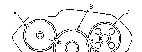
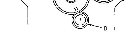
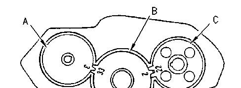
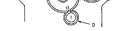
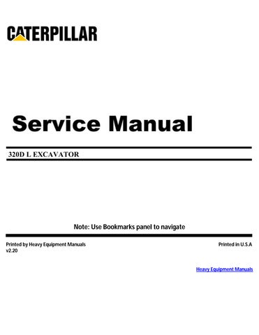
1. Remove cable assembly (1).
2
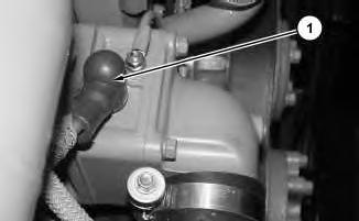
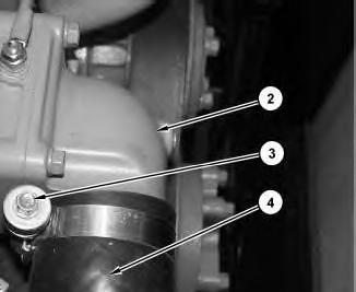
2. Loosen clamp (3). Disconnect hose (4) from air inlet elbow (2).
3
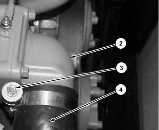
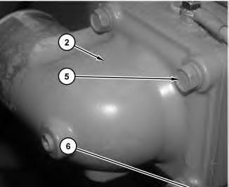
3. Remove bolts (5) and position ground wire (6) out of the way.
4. Remove air inlet elbow (2).
4
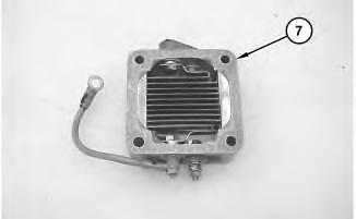
5. Remove air inlet heater (7).

5
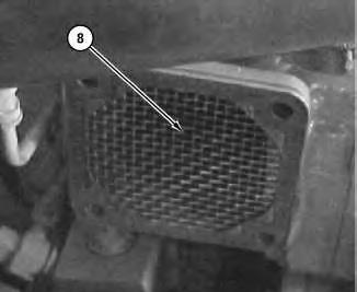
6. Remove wire mesh filter (8).
Installation Procedure
Note: Cleanliness is an important factor. Before assembly, all parts should be thoroughly cleaned in cleaning fluid. Allow the parts to air dry. Wiping cloths or rags should not be used to dry parts. Lint may be deposited on the parts which may cause later trouble. Inspect all parts. If any parts are worn or damaged, use new parts for replacement.
Note: Check the O-ring seals, the gaskets, and the seals for wear or for damage. Replace the components, if necessary.
6
1. Install wire mesh filter (8).

Illustration 7
2. Install air inlet heater (7).
8
3. Install air inlet elbow (2).
4. Position ground wire (6) and install bolts (5).
9
5. Position hose (4) onto air inlet elbow (2).
6. Tighten clamp (3).

7. Install cable assembly (1).
Copyright 1993 - 2025 Caterpillar Inc. All Rights Reserved. Private Network For SIS Licensees. Fri Apr 4 22:44:38 UTC+0700 2025
Product: EXCAVATOR
Model: 320D L EXCAVATOR A8F
Configuration: 320D & 320D L Excavators A8F00001-UP (MACHINE) POWERED BY C6.4 Engine
Disassembly and Assembly
C6.4 Engine for Caterpillar Built Machines
Media Number -KENR8106-09 Publication Date -01/10/2017 Date Updated -18/10/2017
Alternator - Remove and Install
SMCS - 1405-010
Removal Procedure
1. Move the battery disconnect switch to the OFF position.
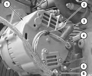
Illustration 1 g01330444
2. Disconnect cable assembly (3).
3. Disconnect harness assemblies (2) and (4) from alternator (1).
4. Disconnect cable assembly (5).
5. Remove bolt (6) and reposition harness assembly (7).
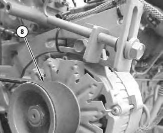
2 g01330445
6. Remove belt (8). Refer to Operation and Maintenance Manual, "BeltsInspect/Adjust/Replace".
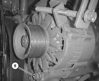
Illustration 3
7. Remove bolt (9) from the alternator.
g01330447
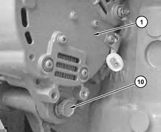
4 g01330442
8. Support alternator (1). Remove bolt (10) from alternator (1).
9. Remove alternator (1) from the machine.
Installation Procedure
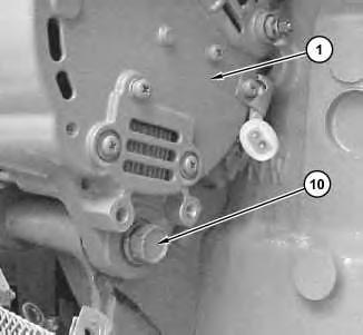
Illustration 5
g01330442
1. Position alternator (1) and install bolt (10).
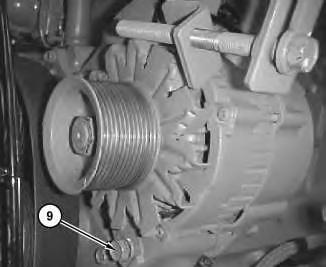
Illustration 6 g01330447
2. Install bolt (9).
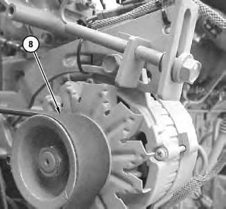
Illustration 7 g01330445
3. Install belt (8). Refer to Operation and Maintenance Manual, "BeltsInspect/Adjust/Replace".
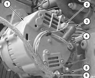
Illustration 8
4. Position harness assembly (7) and install bolt (6) to alternator (1).
5. Connect cable assembly (5).
6. Connect harness assemblies (2) and (4) to alternator (1).
7. Connect cable assembly (3).
8. Move the battery disconnect switch to the ON position.
Product: EXCAVATOR
Model: 320D L EXCAVATOR A8F
Configuration: 320D & 320D L Excavators A8F00001-UP (MACHINE) POWERED BY C6.4 Engine
Disassembly and Assembly
C6.4 Engine for Caterpillar Built Machines
Media Number -KENR8106-09
Bearing Clearance - Check
SMCS - 1203-535; 1219-535
Measurement Procedure Table 1
Required Tools
Plastic Gauge (Green)
to
to
Plastic Gauge (Red)
Plastic Gauge (Blue)
to 0.229 mm (0.004 to 0.009 inch)
Plastic Gauge (Yellow) 0.230 to 0.510 mm (0.009 to 0.020 inch)
Note: Plastic gauge may not be necessary when the engine is in the chassis.
NOTICE
Keep all parts clean from contaminants.
Contaminants may cause rapid wear and shortened component life.
i05977048
Note: Cat does not recommend the checking of the actual bearing clearances particularly on small engines. This is because of the possibility of obtaining inaccurate results and the possibility of damaging the bearing or the journal surfaces. Each Cat engine bearing is quality checked for specific wall thickness.
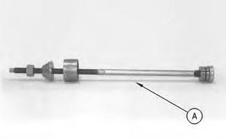
Note: The measurements should be within specifications and the correct bearings should be used. If the crankshaft journals and the bores for the block and the rods were measured during disassembly, no further checks are necessary. However, if the technician still wants to measure the bearing clearances, Tooling (A) is an acceptable method. Tooling (A) is less accurate on journals with small diameters if clearances are less than 0.10 mm (0.004 inch).
NOTICE
Lead wire, shim stock or a dial bore gauge can damage the bearing surfaces.
The technician must be very careful to use Tooling (A) correctly. The following points must be remembered:
• Ensure that the backs of the bearings and the bores are clean and dry.
• Ensure that the bearing locking tabs are properly seated in the tab grooves.
• The crankshaft must be free of oil at the contact points of Tooling (A).
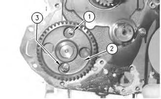
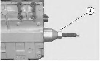
1. Put a piece of Tooling (A) on the crown of the bearing that is in the cap.
Note: Do not allow Tooling (A) to extend over the edge of the bearing.
2. Use the correct torque-turn specifications in order to install the bearing cap. Do not use an impact wrench. Be careful not to dislodge the bearing when the cap is installed.
Note: Do not turn the crankshaft when Tooling (A) is installed.
3. Carefully remove the cap, but do not remove Tooling (A). Measure the width of Tooling (A) while Tooling (A) is in the bearing cap or on the crankshaft journal. Refer to Illustration 1.
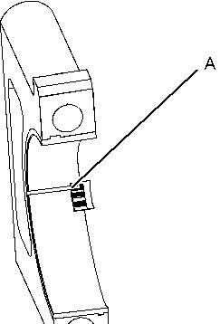

Illustration 1 g01152855
Typical Example
4. Remove all of Tooling (A) before you install the bearing cap.
Note: When Tooling (A) is used, the readings can sometimes be unclear. For example, all parts of Tooling (A) are not the same width. Measure the major width in order to ensure that the parts are within the specification range. Refer to Specifications Manual, "Connecting Rod Bearing Journal" and Specifications Manual, "Main Bearing Journal" for the correct clearances. Copyright 1993 - 2025 Caterpillar Inc.
Product: EXCAVATOR
Model: 320D L EXCAVATOR A8F
Configuration: 320D & 320D L Excavators A8F00001-UP (MACHINE) POWERED BY C6.4 Engine
Disassembly and Assembly
C6.4 Engine for Caterpillar Built Machines
Media Number -KENR8106-09
Publication Date -01/10/2017
Date Updated -18/10/2017
Boost Pressure Sensor - Remove and Install
SMCS - 1917-010
Removal Procedure NOTICE
Keep all parts clean from contaminants.
Contaminants may cause rapid wear and shortened component life.
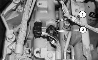
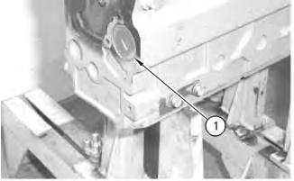
Illustration 1
1. Disconnect harness assembly (2).
g01374366
2. Remove boost pressure sensor (1) and the O-ring seal.