


Product: EXCAVATOR
Model: 320D3 GC EXCAVATOR FLD
Configuration: 320D3 GC Excavator FLD00001-UP (MACHINE) POWERED BY ALUW06DTI Engine
Disassembly and Assembly
320 D3 and 320 D3 GC Hydraulic Excavators Engine Disassembly and Assembly
Media Number -M0095045-03
Publication Date -01/01/2011 Date Updated -12/08/2020
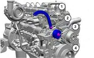
Air Conditioner Support Bracket - Remove and Install
SMCS - 1802-010
S/N - FLD1-UP
Removal Procedure
Start By:
a. Remove the belt tensioner. Refer to "Belt Tensioner - Remove and Install".
NOTICE
Keep all parts clean from contaminants.
Contaminants may cause rapid wear and shortened component life.
i08157783
This is the sample of the manual click on the download link for complete manual
For some reason if link does not work download this pdf and then click
1. Remove bolt (2) and bracket (1).
2. Remove bolt (3) and idler pulley (4).
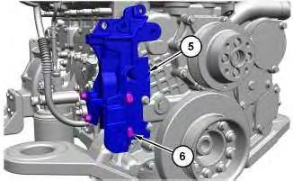
Illustration 2
g06569844
3. Remove bolts (6) and air conditioner support bracket (5).
Installation Procedure
1. Install air conditioner support bracket (5) in the reverse order of removal.
a. Tighten bolts (6) to a torque of 46.5 ± 2.5 N.m (34 ± 1 lb ft).
b. Tighten bolts (3) and (2) to a torque of 46.5 ± 2.5 N.m (34 ± 1 lb ft). Copyright 1993 - 2025 Caterpillar Inc. All Rights Reserved. Private Network For SIS Licensees. Fri Mar 28 00:29:14 UTC+0700 2025
Product: EXCAVATOR
Model: 320D3 GC EXCAVATOR FLD
Configuration: 320D3 GC Excavator FLD00001-UP (MACHINE) POWERED BY ALUW06DTI Engine
Disassembly and Assembly
320 D3 and 320 D3 GC Hydraulic Excavators Engine Disassembly and Assembly
Media Number -M0095045-03
Publication Date -01/01/2011 Date Updated -12/08/2020
Alternator - Remove and Install
SMCS - 1405-010
Removal Procedure NOTICE
Keep all parts clean from contaminants.
Contaminants may cause rapid wear and shortened component life.
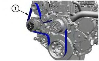
Illustration 1
g06564872
1. Remove belt (1). Refer to Operation and Maintenance Manual , "BeltInspect/Adjust/Replace" for the correct procedure.
i08139345
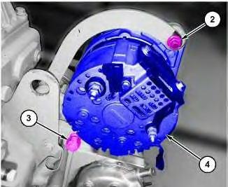
Illustration 2
2. Remove nuts (2), (3), and alternator (4).
Installation Procedure
1. Install alternator (4) in the reverse order of removal.
a. Tighten nuts (3) and (2) to a torque of 46.5 ± 2.5 N.m (34 ± 1 lb ft). Copyright 1993 - 2025 Caterpillar Inc. All Rights Reserved. Private Network For SIS Licensees. Fri Mar 28 00:28:43 UTC+0700 2025
Product: EXCAVATOR
Model: 320D3 GC EXCAVATOR FLD
Configuration: 320D3 GC Excavator FLD00001-UP (MACHINE) POWERED BY ALUW06DTI Engine
Disassembly and Assembly
320 D3 and 320 D3 GC Hydraulic Excavators Engine Disassembly and Assembly
Media Number -M0095045-03
Publication Date -01/01/2011 Date Updated -12/08/2020
Belt Tensioner - Remove and Install
SMCS - 1358-010; 4197-010
Removal Procedure
NOTICE
Keep all parts clean from contaminants.
Contaminants may cause rapid wear and shortened component life.
Illustration 1 g06564872
1. Remove belt (1). Refer to Operation and Maintenance Manual , "BeltInspect/Adjust/Replace" for the correct procedure.
i08157784
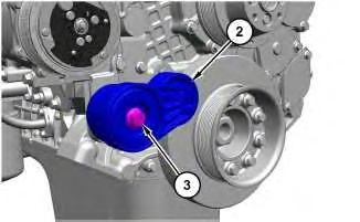
Illustration 2
2. Remove bolt (3) and belt tensioner (2).
Installation Procedure
1. Install belt tensioner (2) in the reverse order of removal.
a. Tighten bolt (3) to a torque of 46.5 ± 2.5 N.m (34 ± 1 lb ft).
Copyright 1993 - 2025 Caterpillar Inc. All Rights Reserved. Private Network For SIS Licensees. Fri Mar 28 00:28:27 UTC+0700 2025
Product: EXCAVATOR
Model: 320D3 GC EXCAVATOR FLD
Configuration: 320D3 GC Excavator FLD00001-UP (MACHINE) POWERED BY ALUW06DTI Engine
Disassembly and Assembly
320 D3 and 320 D3 GC Hydraulic Excavators Engine Disassembly and Assembly
Media Number -M0095045-03 Publication Date -01/01/2011 Date Updated -12/08/2020
Camshaft - Remove and Install
SMCS - 1210-010
S/N - FLD1-UP
Removal Procedure
Table 1
Required Tools Tool
Start By:
i08161691
a. Remove the rocker shaft and push rod. Refer to "Rocker Shaft and Push Rod - Remove and Install".
b. Remove the front housing. Refer to "Housing (Front) - Remove and Install".
NOTICE
Care must be used when removing or installing the camshaft. Do not damage the finished surfaces of the camshaft or the camshaft bearings.
NOTICE
Keep all parts clean from contaminants.
Contaminants may cause rapid wear and shortened component life.
2
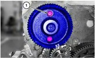
1. Place alignment marks on the camshaft gear and the oil pump gear prior to removal for installation purposes.
2. Remove bolts (1) and camshaft (2).
Note: Ensure that the camshaft bearings are not damaged while removal of camshaft (2).
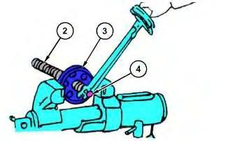
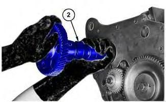
Illustration 3
3. Use suitable vice and Tooling (A) (not shown) to remove camshaft gear (3). Remove bolt (4), the washer, camshaft gear (3), and the camshaft plate.
Installation Procedure

Illustration 4
g06572452
1. Raise the temperature of camshaft gear (3) to 108° C (226° F) in a period of 90 to 100 seconds.
2. Install the camshaft plate, camshaft gear (3) onto camshaft (2).
3. Apply a thin coat of engine oil to the threads of bolt (4).
4. Install the washer and bolt (4). Tighten bolt (4) to a torque of 100 ± 10 N·m (73 ± 7 lb ft). Turn bolt (4) to an additional angle of 60 ± 5 degrees.
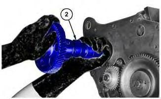
Illustration 5
5. Set the engine to top center for cylinder number one. Refer to Testing and Adjusting, "Finding Top Center Position for No. 1 Piston" for the correct procedure.
6. Lubricate the journals of camshaft (2) lightly with the engine oil. Install camshaft (2) into the cylinder block.
Note: Ensure that the camshaft bearings are not damaged while installation of camshaft (2).
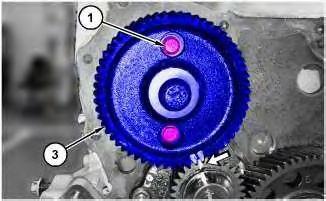
Illustration 6
g06572773
7. Align the timing marks of camshaft gear (3) with the corresponding timing marks on the oil pump gear as shown in Illustration 6.
8. Apply a thin coat of engine oil to the threads of bolts (1).
9. Install bolts (1). Tighten bolts (1) to a torque of 22.5 ± 3.5 N·m (199 ± 31 lb in).
End By:
a. Install the front housing. Refer to "Housing (Front) - Remove and Install".
b. Install the rocker shaft and push rod. Refer to "Rocker Shaft and Push Rod - Remove and Install".
Product: EXCAVATOR
Model: 320D3 GC EXCAVATOR FLD
Configuration: 320D3 GC Excavator FLD00001-UP (MACHINE) POWERED BY ALUW06DTI Engine
Disassembly and Assembly
320 D3 and 320 D3 GC Hydraulic Excavators Engine Disassembly and Assembly
Media Number -M0095045-03
Publication Date -01/01/2011 Date Updated -12/08/2020
Crankcase Breather - Remove and Install
SMCS - 1317-010
S/N - FLD1-UP
Removal Procedure
NOTICE
Keep all parts clean from contaminants.
Contaminants may cause rapid wear and shortened component life.
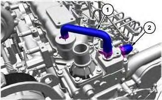
Illustration 1 g06561109
1. Loosen the clamps and remove hoses (1) and (2).
i08134930
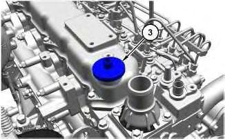
2. Remove crankcase breather (3) and the washer.
Installation Procedure
1. Install crankcase breather (3) in the reverse order of removal.
Copyright 1993 - 2025 Caterpillar Inc. All Rights Reserved. Private Network For SIS Licensees. Fri Mar 28 00:23:53 UTC+0700 2025
Product: EXCAVATOR
Model: 320D3 GC EXCAVATOR FLD
Configuration: 320D3 GC Excavator FLD00001-UP (MACHINE) POWERED BY ALUW06DTI Engine
Disassembly and Assembly
320 D3 and 320 D3 GC Hydraulic Excavators Engine Disassembly and Assembly
Media Number -M0095045-03 Publication Date -01/01/2011 Date Updated -12/08/2020
Crankshaft - Remove and Install - Includes Crankshaft Gear and Bearings
SMCS - 1202-010
S/N - FLD1-UP
Removal Procedure Table 1
Start By:
a. Remove the flywheel housing. Refer to "Flywheel Housing - Remove and Install".
b. Remove the front gear group. Refer to "Gear Group (Front) - Remove and Install".
c. Remove the engine oil pan. Refer to "Engine Oil Pan - Remove and Install".
NOTICE
Keep all parts clean from contaminants. Contaminants may cause rapid wear and shortened component life.
1. Use a suitable stand and position the engine in the INVERTED position.
1
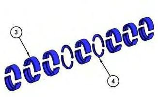
Illustration 2
g06571507
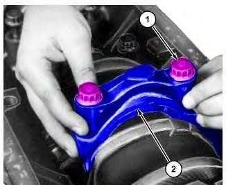
Note: Place an identification mark on all crankshaft main bearing caps (2). Crankshaft main bearing caps (2) should be marked with the crankcase punching mark 1 to 7, commencing from the timing gear side.
2. Remove bolts (1), crankshaft main bearing caps (2), and lower half of crankshaft main bearings (3). Remove crankshaft thrust bearings (4).
Note: Arrange all the crankshaft main bearing caps and the crankshaft thrust bearings for installation purposes.
3. Remove the connecting rod caps and the lower half of the connecting rod bearings.
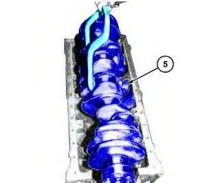
Illustration 3
g06573683
4. Use suitable lifting device to remove crankshaft (5). The weight of crankshaft (5) is approximately 46 kg (101 lb).
5. Remove crankshaft (5) and upper half of the crankshaft main bearings.
6. Remove upper half of the connecting rod bearings.
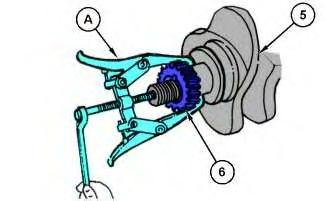
Illustration 4
g06571511
7. Use Tooling (A) to remove gear (6) from crankshaft (5). Remove gear (6).
Installation procedure
1. Clean the crankcase, the crankshaft, and the bearing shells by blowing compressed air through the lubrication holes.
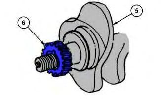
Illustration 5
2. Raise the temperature of gear (6) to approximately 130° C (266° F). Install gear (6) onto crankshaft (5).
3. Lubricate the bearing shells with the engine oil. Install the upper half of the connecting rod bearings and the upper half of the crankshaft main bearings.
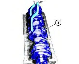
Illustration 6
g06573683
4. Use suitable lifting device to install crankshaft (5). The weight of crankshaft (5) is approximately 46 kg (101 lb). Carefully lower crankshaft (5) into position. Install crankshaft (5).
5. Lubricate the crankshaft journals with the engine oil.
Illustration 7
g06255058
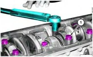
Illustration 8
g06571653
6. Lubricate the bearing shells and the threads of bolts (1) with the engine oil.
7. Install lower half of the crankshaft main bearing, crankshaft main bearing cap (2), and bolts (1).
8. Tighten bolts (1) uniformly in the three stages in sequence 4-5-3-6-2-7-1 to a torque of 140 ± 15 N·m (103 ± 11 lb ft). Turn bolts (1) to an additional angle of 90 ± 5 degrees.
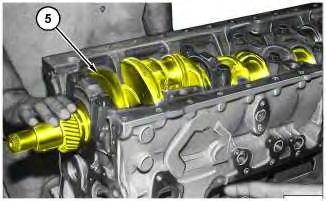
Illustration 9
Note: Do not attempt to rotate the crankshaft before all the bearing caps have been bolted down. The crankshaft must turn freely without binding.
9. Turn crankshaft (5) to at least one revolution by giving a strong push by hand.
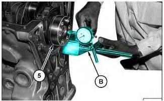
Illustration 10
g06572317
10. Use Tooling (B) to check end play of crankshaft (5).
11. Slide crankshaft (5) in one axial direction and measure the gap between thrust bearing side and the crank web face.
12. The initial end clearance with the new thrust bearing and the main bearings should be 0.050 to 0.125 mm (0.0020 to 0.0049 inch).
13. Install the lower half of the connecting rod bearings, the connecting rod caps, and the bolts. Tighten the bolts to a torque of 100 ± 10 N·m (74 ± 7 lb ft). Turn the bolts to an additional angle of 60 ± 5 degrees.
End By:
a. Install the engine oil pan. Refer to "Engine Oil Pan - Remove and Install".
b. Install the front housing. Refer to "Gear Group (Front) - Remove and Install".
c. Install the flywheel housing. Refer to "Flywheel Housing - Remove and Install".
Copyright 1993 - 2025 Caterpillar Inc.
Product: EXCAVATOR
Model: 320D3 GC EXCAVATOR FLD
Configuration: 320D3 GC Excavator FLD00001-UP (MACHINE) POWERED BY ALUW06DTI Engine
Disassembly and Assembly
320 D3 and 320 D3 GC Hydraulic Excavators Engine Disassembly and Assembly
Media Number -M0095045-03
Publication Date -01/01/2011 Date Updated -12/08/2020
Crankshaft Front Seal - Remove and Install
SMCS - 1160-010
Removal Procedure
Start By:
a. Remove crankshaft vibration damper and pulley.
NOTICE
Keep all parts clean from contaminants.
Contaminants may cause rapid wear and shortened component life.
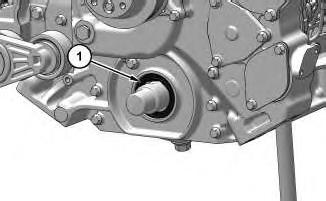
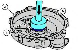
Illustration 1
1. Use a suitable Tooling to remove crankshaft front seal (1). Remove crankshaft front seal (1).
Note: Do not damage the edge of the housing for the crankshaft front seal.
Installation Procedure
1
533-5708 Seal Installer Tool 1
Illustration 2 g06318334
1. Use Tooling (A) to install crankshaft front seal (1). Install crankshaft front seal (1). Copyright 1993 - 2025 Caterpillar Inc. All Rights Reserved. Private Network For SIS Licensees.
Product: EXCAVATOR
Model: 320D3 GC EXCAVATOR FLD
Configuration: 320D3 GC Excavator FLD00001-UP (MACHINE) POWERED BY ALUW06DTI Engine
Disassembly and Assembly
320 D3 and 320 D3 GC Hydraulic Excavators Engine Disassembly and Assembly
Media Number -M0095045-03
Publication Date -01/01/2011 Date Updated -12/08/2020
Crankshaft Rear Seal - Remove and Install
SMCS - 1161-010
Removal Procedure
Start By:
a. Remove the flywheel housing.
NOTICE
Keep all parts clean from contaminants.
Contaminants may cause rapid wear and shortened component life.

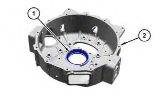
Illustration 1 g06318269
1. Remove oil seal (1) from flywheel housing (2).
i07426616