

Note: Use Bookmarks panel to navigate
Note: Use Bookmarks panel to navigate
For some reason if link does not work download this pdf and then click

Product: EXCAVATOR
Model: 320C EXCAVATOR SBN
Configuration: 320C & 320C L Excavators SBN00001-UP (MACHINE) POWERED BY 3066 Engine
Disassembly and Assembly
320C Excavator Machine Systems
Media Number -RENR3826-16
SMCS - 5077-011-PS; 5077-012-PS
Removal Procedure
Start By:
a. Release the hydraulic system pressure. Refer to Disassembly and Assembly, "Hydraulic System Pressure - Release".
Note: The hydraulic accumulator is installed under the main control valve.
NOTICE
Care must be taken to ensure that fluids are contained during performance of inspection, maintenance, testing, adjusting, and repair of the product. Be prepared to collect the fluid with suitable containers before opening any compartment or disassembling any component containing fluids.
Refer to Special Publication, NENG2500, "Dealer Service Tool Catalog" for tools and supplies suitable to collect and contain fluids on Cat® products.
Dispose of all fluids according to local regulations and mandates.
At operating temperature, the hydraulic oil is hot and under pressure. Hot oils can cause burns.
To prevent possible personal injury, release the pressure in the work tool hydraulic circuit (boom, stick, bucket, and swing), travel circuits, and the hydraulic oil tank at the filler cap before any hydraulic lines or components are disconnected or removed.
Remove the filler cap only when the engine is stopped and the filler cap is cool enough to touch.
Note: A hydraulic oil sample should be obtained before any maintenance is performed in order to establish the system contaminant level. Refer to Fluid Analysis Laboratory Guide, SEBF3116, "Obtaining an Oil Sample for S·O·S Analysis". Refer to Operation and Maintenance Manual, "Sampling Interval and Location of Sampling Valve" for the correct location.
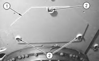
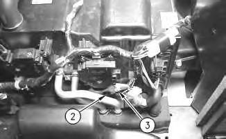
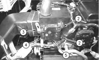
1. Remove bolts (2).
2. Remove sheet (1). Sheet (1) weighs approximately 6 kg (13 lb).

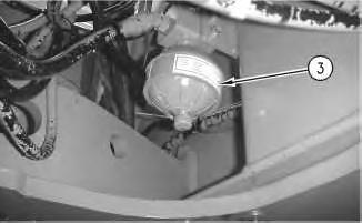
Note: Do not release the nitrogen from the hydraulic accumulator unless the unit will be disassembled.
3. Remove hydraulic accumulator (3) by turning the nut that is located at the top of the accumulator. Remove the O-ring seal from the accumulator.
Table 1
Required Tools
Tool Part Number Part Description Qty
A 1U-6396 O-Ring Assembly Compound
B
7S-5437 Nitrogen Charging Group 1
7S-5439 Extension Assembly 1
Note: O-ring seals, gaskets, and seals should always be replaced. A used O-ring seal may not have the same sealing properties as a new O-ring seal. Use Tooling (A) during the assembly procedure.
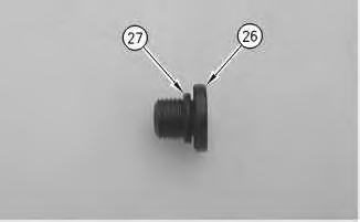
1. Replace the O-ring seal with a new O-ring seal. Install the O-ring seal in the accumulator.
3
2. Install hydraulic accumulator (3) by tightening the nut that is located at the top of the accumulator.
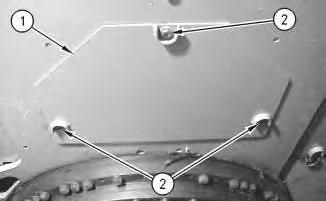
3. Install sheet (1). Install bolts (2).
4. If the hydraulic accumulator was disassembled, use Tooling (B) to recharge the hydraulic accumulator.
5. Check the oil level in the hydraulic oil tank. Fill the hydraulic oil tank with oil to the correct level. Refer to the Operation and Maintenance Manual, "Lubricant Viscosities" for the proper oil viscosity. Refer to the Operation and Maintenance Manual, "Hydraulic System Oil Level - Check" for the correct filling procedure.
6. Install high efficiency filters in place of the pilot filter, the case drain filter, and the return filter.
Note: High efficiency filters should not be run for more than 250 hours before you change back to the standard filters.
7. Obtain a hydraulic oil sample from the main S·O·S port.
Reference: Refer to Operation and Maintenance Manual, "Sampling Interval and Location of Sampling Valve" for the correct location.
8. If the S·O·S sample exceeds ISO 18/15, flush the hydraulic system.
Reference: Refer to Contamination Control Guidelines, SEBF8436, "Hydraulic System Flushing Procedure for 320C Hydraulic Excavators" for further information.
Copyright 1993 - 2024 Caterpillar Inc. All Rights Reserved. Private Network For SIS Licensees.
Wed Nov 13 16:04:26 UTC+0530 2024
Product: EXCAVATOR
Model: 320C EXCAVATOR SBN
Configuration: 320C & 320C L Excavators SBN00001-UP (MACHINE) POWERED BY 3066 Engine
Disassembly and Assembly
320C Excavator Machine Systems
Media Number -RENR3826-16
SMCS - 7304-010-MQ; 7309-010-MQ; 7320-010-MQ
Removal Procedure
Start By:
a. Remove the storage box in the cab. Refer to Disassembly and Assembly, "Storage Box and Covers (Cab) - Remove and Install".
Removal Procedure of the Actuator Motor for the Air Damper for the Temperature Control
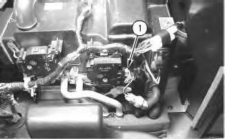
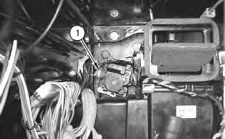
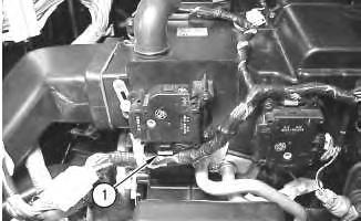
Illustration 1 g00699772
1. Disconnect harness assembly (1) from the actuator motor.
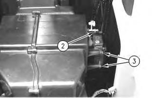
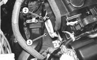
2
2. Remove screw (2) in order to disconnect linkage (3).
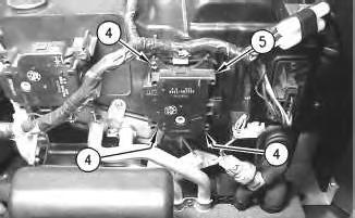
Illustration 3
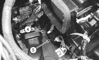
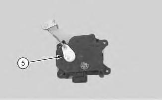
3. Remove screws (4) from the actuator motor.
4. Remove actuator motor (5).
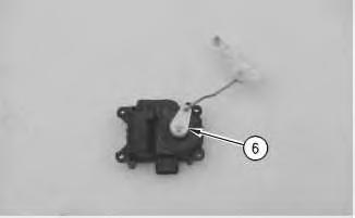
Illustration 4
5. Remove linkage (6) from the actuator motor.

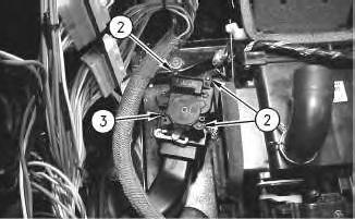
1. Disconnect harness assembly (1) from the actuator motor.

6
2. Remove screw (4). Remove the cable strap for the harness assembly.
3. Remove screws (2) from the actuator motor.
4. Remove actuator motor (5).
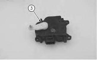
Illustration 7
g00699816
5. Remove linkage (3) from the actuator motor.
Removal Procedure of the Actuator Motor for the Fresh Air or Recirculated Air Damper

8
g00699825
1. Disconnect harness assembly (1) from the actuator motor.
9
2. Remove screw (2) from the linkage.
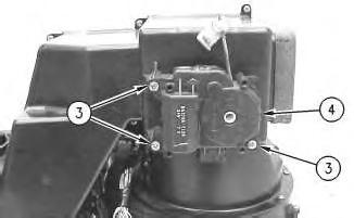
Illustration 10
g00699833
The heating and air conditioning unit is removed for photographic purposes.
3. Remove screws (3) from the actuator motor.
4. Remove actuator motor (4).
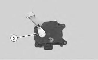
Illustration 11
g00699850
5. Remove linkage (5) from the actuator motor.
Removal Procedure of the Actuator Motor for the Air Damper for the Rear Window Defroster
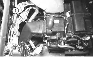
Illustration 12
1. Remove air duct (1).
13
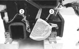
Illustration 14 g00699876
The heating and air conditioning unit is removed for photographic purposes.
2. Disconnect harness assembly (2) from the actuator motor.
3. Remove cam (3) from the actuator motor.
15
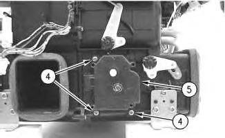
Illustration 16
g00699881
The heating and air conditioning unit is removed for photographic purposes.
4. Remove screws (4).
5. Remove actuator motor (5).
Removal Procedure of the Actuator Motor for the Air Damper for the Front Window
17
1. Disconnect harness assembly (1) from the actuator motor.
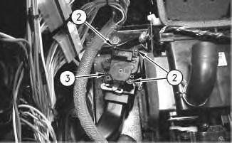
Illustration 18
2. Remove screws (2).
3. Remove actuator motor (3).
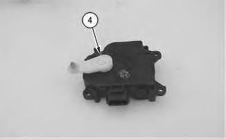
Illustration 19
g00699909
4. Remove linkage (4) from the actuator motor.
Installation Procedure
Installation Procedure of the Actuator Motor for the Air Damper for the Temperature Control
20
1. Install linkage (6) on the actuator motor.
21
2. Install actuator motor (5) on the heating and air conditioning unit.
3. Install screws (4) in the actuator motor.
Illustration 22
Note: Make sure that the linkage is properly aligned in the air actuator.
4. Connect linkage (3). Install screw (2).
23
5. Connect harness assembly (1) to the actuator motor.
Installation Procedure of the Actuator Motor for the Front Air Damper
Illustration 24
1. Install linkage (3) on the actuator motor.
25
Note: Make sure that linkage (3) is properly aligned with the air actuator.
2. Install actuator motor (5).
3. Install screws (2) in the actuator motor.
4. Install a new cable strap for the harness assembly. Install screw (4).
26
5. Connect harness assembly (1) to the actuator motor.
Installation Procedure of the Actuator Motor for the Fresh Air or Recirculated Air Damper
27
1. Install linkage (5) on the actuator motor.
Illustration 28
g00699833
The heating and air conditioning unit is removed for photographic purposes.
2. Install actuator motor (4).
3. Install screws (3) in the actuator motor.

Illustration 29
4. Connect the linkage to the air actuator.
5. Install screw (2) in the linkage.
g00699828
30
6. Connect harness assembly (1) to the actuator motor.
Installation Procedure of the Actuator Motor for the Air Damper for the Rear Window Defroster
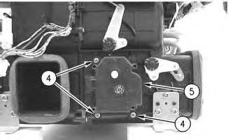
Illustration 31
g00699881
The heating and air conditioning unit is removed for photographic purposes.
1. Install actuator motor (5).
2. Install screws (4).
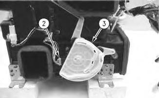
Illustration 32
g00699876
The heating and air conditioning unit is removed for photographic purposes.
Note: Make sure that the linkages for the air dampers are installed in the cam.
3. Install cam (3) on the actuator motor.
4. Connect harness assembly (2) to the actuator motor.
Illustration 33
5. Install air duct (1).
Installation Procedure of the Actuator Motor for the Air Damper for the Front Window
Illustration 34
1. Install linkage (4) on the actuator motor.
35
2. Install actuator motor (3).
3. Install screws (2).
36
4. Connect harness assembly (1) to the actuator motor.
End By:
a. Install the storage box in the cab. Refer to Disassembly and Assembly, "Storage Box and Covers (Cab) - Remove and Install". Copyright 1993 - 2024 Caterpillar Inc. All Rights Reserved. Private Network For SIS Licensees. Wed Nov 13 15:32:22 UTC+0530 2024
Product: EXCAVATOR
Model: 320C EXCAVATOR SBN
Configuration: 320C & 320C L Excavators SBN00001-UP (MACHINE) POWERED BY 3066 Engine
Disassembly and Assembly
320C Excavator Machine Systems
Media Number -RENR3826-16
Date -01/11/2014 Date Updated -30/03/2016
SMCS - 5059-016-AX
Assembly Procedure
Table 1
Required Tools
Tool Part Number Part Description Qty (A) 1U-6396 O-Ring Assembly Compound 1
Note: Cleanliness is an important factor. Before assembly, all parts should be thoroughly cleaned in cleaning fluid. Allow the parts to air dry. Wiping cloths or rags should not be used to dry parts Lint may be deposited on the parts which may cause later trouble. Inspect all parts. If any parts are worn or damaged, use new parts for replacement. All disassembly and all assembly procedures must be performed on a clean work surface and in a clean hydraulic area. Keep cleaned parts covered and protected at all times.
Note: O-rings, gaskets, and seals should always be replaced. A used O-ring may not have the same sealing properties as a new O-ring. Use Tooling (A) during the assembly procedure.
For some reason if link does not work download this pdf and then click