

For some reason if link does not work download this pdf and then click

Product: INDUSTRIAL ENGINE
Model: 3176C INDUSTRIAL ENGINE 2AW
Configuration: 3176C Industrial Engine 2AW00001-UP
Disassembly and Assembly
3176C and 3196 Industrial Engines
SMCS - 1207-016
Assembly Procedure Table 1
Required Tools
1P-1858 Retaining Ring Pliers 1
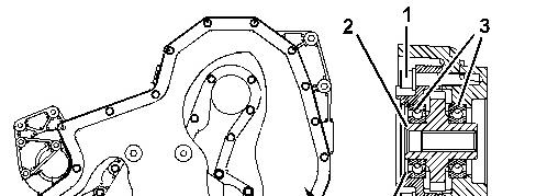
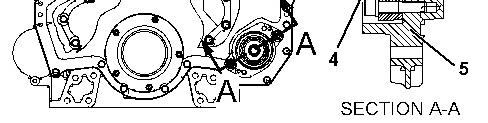
Illustration 1 g01062840
1. Lower the temperature of gear and shaft (2).
Always wear protective gloves when handling parts that have been heated.
2. Raise the temperature of bearings (3).
3. Place bearings (3) in the original location on gear and shaft (2).
4. Use Tooling (B) in order to install retaining ring (4) into accessory drive housing (5).
5. Install gear and shaft (2) with bearings (3) into accessory drive housing (5).
6. Install bolts (1).
End By:
a. Install the accessory drive. Refer to Disassembly and Assembly, "Accessory Drive - Install".
1993 - 2025 Caterpillar Inc.
Product: INDUSTRIAL ENGINE
Model: 3176C INDUSTRIAL ENGINE 2AW
Configuration: 3176C Industrial Engine 2AW00001-UP
Disassembly and Assembly
3176C and 3196 Industrial Engines
SMCS - 1207-015
Disassembly Procedure Table 1 Required Tools
Start By:
a. Remove the accessory drive. Refer to Disassembly and Assembly, "Accessory DriveRemove".
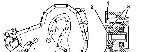
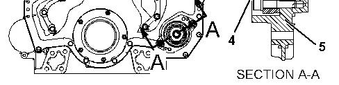
Illustration 1 g01062840
1. Remove bolts (1).
2. Remove gear and shaft (2) with bearings (3) from accessory drive housing (5).
Note: One end of the gear shaft is longer than the opposite end. Prior to assembly, ensure that the gear shaft is in the correct position.
3. Use Tooling (A) in order to remove bearings (3) from gear and shaft (2).
4. Use Tooling (B) in order to remove retaining ring (4) from accessory drive housing (5).
Product: INDUSTRIAL ENGINE
Model: 3176C INDUSTRIAL ENGINE 2AW
Configuration: 3176C Industrial Engine 2AW00001-UP
Disassembly and Assembly
3176C and 3196 Industrial Engines Media
SMCS - 1207-012
Installation Procedure
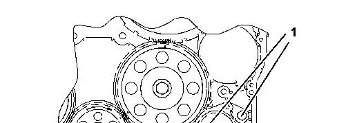
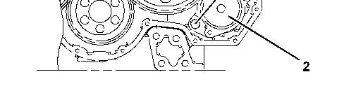
Illustration 1 g01021789
Typical example
1. Install accessory drive (2).
2. Install bolts (1) and the washers. Tighten the bolts to a torque of 100 ± 20 N·m (74 ± 15 lb ft).
End By:
a. Install the front cover. Refer to Disassembly and Assembly, "Front Cover - Install".
b. Install the belt tensioner. Refer to Disassembly and Assembly, "Belt Tensioner - Remove and Install".
Copyright 1993 - 2025 Caterpillar Inc. All Rights Reserved. Private Network For SIS Licensees.
Fri Jan 24 01:50:54 UTC+0530 2025
Product: INDUSTRIAL ENGINE
Model: 3176C INDUSTRIAL ENGINE 2AW
Configuration: 3176C Industrial Engine 2AW00001-UP
Disassembly and Assembly
3176C and 3196 Industrial Engines
SMCS - 1207-011
Removal Procedure
Start By:
a. Remove the belt tensioner. Refer to Disassembly and Assembly, "Belt Tensioner - Remove and Install".
b. Remove the front cover. Refer to Disassembly and Assembly, "Front Cover - Remove".
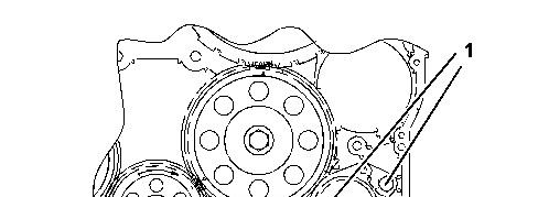
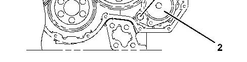
Illustration 1 g01021789 Typical example
1. Remove bolts (1) and the washers.
2. Remove accessory drive (2).
Copyright 1993 - 2025 Caterpillar Inc. All Rights Reserved.
Network For SIS Licensees. Fri Jan 24 01:49:43 UTC+0530 2025
Product: INDUSTRIAL ENGINE
Model: 3176C INDUSTRIAL ENGINE 2AW
Configuration: 3176C Industrial Engine 2AW00001-UP
Disassembly and Assembly
3176C and 3196 Industrial Engines
SMCS - 1803-016
Assembly Procedure Table 1
Tools
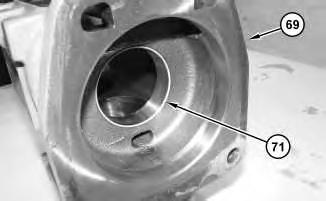
Illustration 1
1. Install bearing (71) into compressor housing (69).
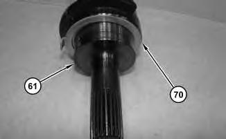
Illustration 2
g02961417
2. Install thrust washer (70) onto crankshaft (61).
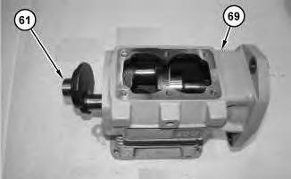
Illustration 3
g02961398
3. Install crankshaft (61) into compressor housing (69).
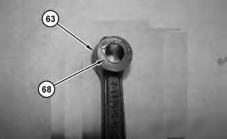
Illustration 4
g02961381
4. Install bearing (68) into connecting rod (63). Repeat this step for the remaining connecting rod assembly
5
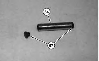
5. Install caps (67) onto wrist pin (64).
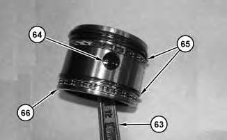
Illustration 6
6. Install piston rings (65). Install piston (66) onto connecting rod (63). Install wrist pin (64). Repeat this step for the remaining piston and connecting rod assembly.
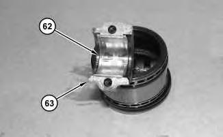
Illustration 7
g02961340
7. Install bearing (62) onto connecting rod (63). Repeat this step for the remaining connecting rod.
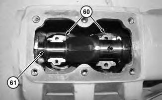
Illustration 8
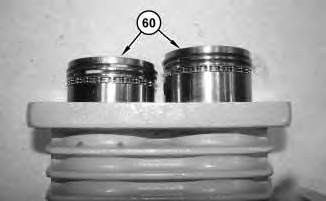
Illustration 9
g02961337
8. Install piston and connecting rod assemblies (60). Push piston and connecting rod assemblies (60) into the block and onto crankshaft (61).
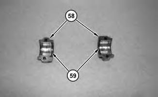
Illustration 10
g02961321
9. Install bearings (59) onto bearing caps (58).
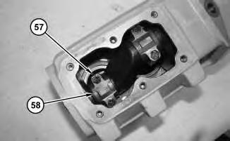
11
10. Install bearing cap (58). Install bolts (57). Repeat this step for the remaining bearing cap.
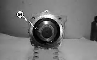
Illustration 12
11. Install thrust washer (56).
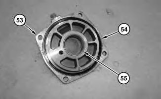
Illustration 13
12. Install bearing (55) and O-ring seal (54) onto cover (53).
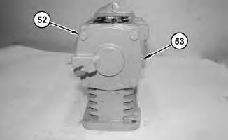
Illustration 14
13. Install cover (53). Install bolts (52).
g02961216
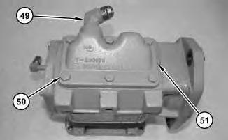
Illustration 15
g02961198
14. Install cover (51). Install bolts (50). Install fitting (49).
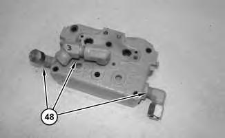
Illustration 16
15. Install fittings (48).
g02960987
17
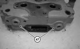
16. Apply Tooling (B) onto plugs (47). Install plugs (47).
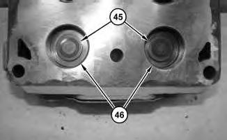
Illustration 18
17. Install valve seats (46). Install inlet valves (45).
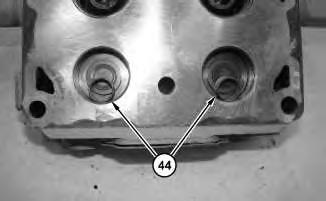
Illustration 19
18. Install inlet valve springs (44).
20
Improper assembly of parts that are spring loaded can cause bodily injury.
To prevent possible injury, follow the established assembly procedure and wear protective equipment.
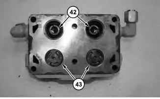
19. Use Tooling (A) to install inlet valves (43). Install valves (42).
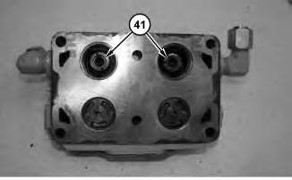
Illustration 21
20. Install springs (41).
g02960818
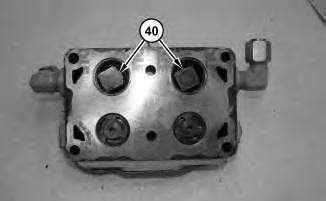
Improper assembly of parts that are spring loaded can cause bodily injury.
To prevent possible injury, follow the established assembly procedure and wear protective equipment.
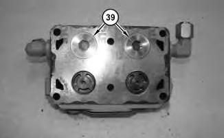
Install valve seats (39).
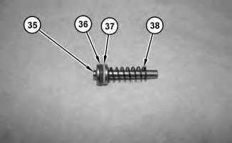
23. Install spring (38), backup ring (37), and O-ring seal (36) onto unloader valve (35). Repeat this step for the remaining unloader valve (35).
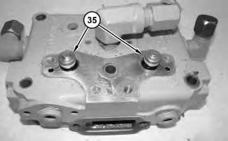
24. Install unloader valves (35).
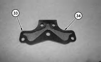
25. Install gasket (34) onto unloader cover (33).
27
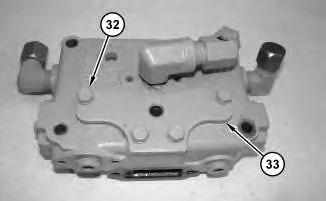
Improper assembly of parts that are spring loaded can cause bodily injury.
To prevent possible injury, follow the established assembly procedure and wear protective equipment.
26. Install unloader cover (33) and bolts (32). T
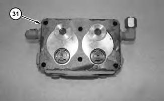
Illustration 28
27. Install gasket (31).
g02960722
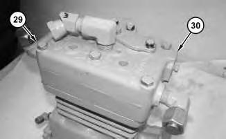
Illustration 29
g02960696
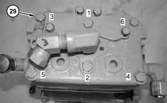
Illustration 30
g02962830
28. Install head (30) and bolts (29). Tighten bolts (29) to a torque of 23 N·m (200 lb in) in a crisscross pattern in the order indicated. Tighten bolts (29) again to a torque of 45 to 57 N·m (400 to 500 lb in) in a crisscross pattern in the order indicated.
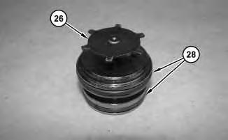
Illustration 31
g02960676
29. Install O-ring seals (28) onto valve assembly (26).
32
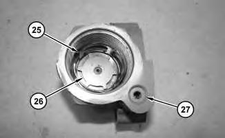
30. Install check valve (27), valve assembly (26), and spacer (25).
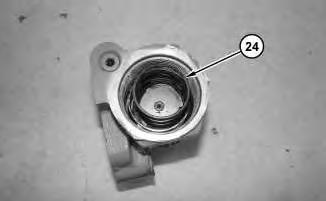
Illustration 33
31. Install spring (24).
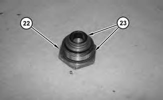
Illustration 34
32. Install O-ring seals (23) onto locking nut (22).
35
Improper assembly of parts that are spring loaded can cause bodily injury.
To prevent possible injury, follow the established assembly procedure and wear protective equipment.
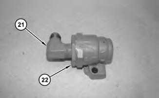
33. Install locking nut (22). Apply Tooling (B) onto fitting (21). Install fitting (21).
36
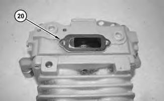
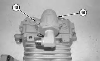
34. Install gasket (20). Install manifold (19). Install bolts (18).
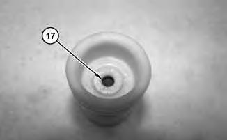
35. Install O-ring seal (17).
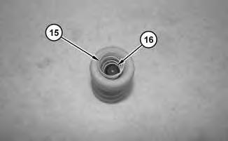
36. Install valve (16). Install spring (15).
For some reason if link does not work download this pdf and then click