

Note: Use Bookmarks panel to navigate
This is the sample of the manual click on the download link for complete manual
DOWNLOAD LINK
For some reason if link does not work download this pdf and then click

Product: EXCAVATOR
Model: 318F L EXCAVATOR HCP
Configuration: 318F L Excavator HCP00001-UP (MACHINE) POWERED BY C4.4 Engine
Disassembly and Assembly
316F, 318F Excavator Machine Systems
Media Number -UENR5585-05
Accumulator
SMCS - 4331; 5077; 7336
Specification
Publication Date -01/08/2015
Date Updated -14/12/2017
i04606832
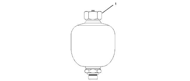
Illustration 1
g02592601
Table 1
Specification for 352-6990 Accumulator Gp
Item Qty Part
Specification Description
1 - - Torque for the protecting cap 30 to 35 N·m (266 to 310 lb in).
Removal Procedure
Start By:
a. Release the hydraulic system pressure.
At operating temperature, the hydraulic oil is hot and under pressure. Hot oils can cause burns.
To prevent possible personal injury, release the pressure in the work tool hydraulic circuit (boom, stick, bucket, and swing), travel circuits, and the hydraulic oil tank at the filler cap before any hydraulic lines or components are disconnected or removed.
Remove the filler cap only when the engine is stopped and the filler cap is cool enough to touch.
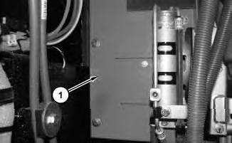
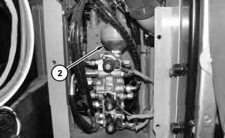
Note: Do not release the nitrogen from the hydraulic accumulator unless the unit will be disassembled.
3. Remove accumulator (2) by turning the nut that is located at the top of the accumulator. Remove the O-ring seal from the accumulator.
Installation Procedure
1. Replace the O-ring seal with a new O-ring seal. Install the O-ring seal in the accumulator.
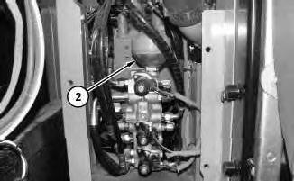
2. Install accumulator (2). Refer to Testing and Adjusting, "Accumulator (Pilot) - Test and Charge" if the accumulator requires charging.
3. Install panel (1).
4. Check the hydraulic oil level. Refer to Operation and Maintenance Manual, "Hydraulic System Oil Level - Check".
Copyright 1993 - 2024 Caterpillar Inc. All Rights Reserved. Private Network For SIS Licensees.
Tue Mar 19 23:11:23 UTC+0530 2024

Product: EXCAVATOR
Model: 318F L EXCAVATOR HCP
Configuration: 318F L Excavator HCP00001-UP (MACHINE) POWERED BY C4.4 Engine
Disassembly and Assembly
316F, 318F Excavator Machine Systems
Media Number -UENR5585-05
Publication Date -01/08/2015
Actuator Motor (Air Distributor)
SMCS - 7304-MQ; 7309-MQ; 7320-MQ
Removal Procedure
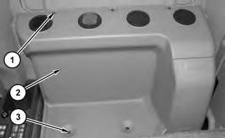
Illustration 1
g02412816
1. Remove bolts (1) and (3). Remove cover (2).
Date Updated -14/12/2017
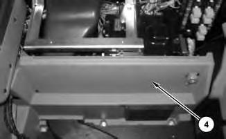
Illustration 2
2. Remove cover (4).
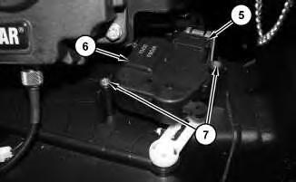
3 g02412877
3. Disconnect harness assembly (5). Remove screws (7). Remove actuator (6).
Installation Procedure
1. Install actuator (6) in reverse order of removal.
1993 - 2024 Caterpillar Inc.
Network For SIS Licensees. Tue Mar 19 22:59:31 UTC+0530 2024
Product: EXCAVATOR
Model: 318F L EXCAVATOR HCP
Configuration: 318F L Excavator HCP00001-UP (MACHINE) POWERED BY C4.4 Engine
Disassembly and Assembly
316F, 318F Excavator Machine Systems
Media Number -UENR5585-05
Publication Date -01/08/2015
Auxiliary Pilot Valve (Straight Travel)
SMCS - 5059; 5065; 5479
Specifications
Date Updated -14/12/2017
i04641896
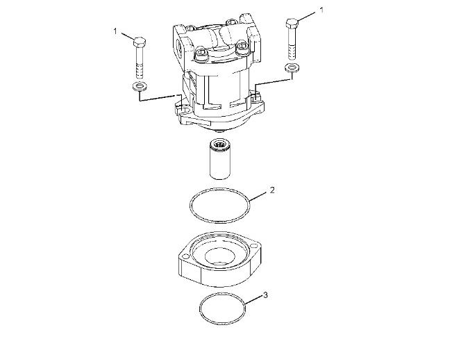
Specification for 342-1891 Auxiliary Pump and Mounting Gp
Lubricate the sliding surfaces lightly with the hydraulic oil.
1 2 8T-6466 Bolt Torque to 55 ± 10 N·m (41 ± 7 lb ft).
2 1 273-8315 O-Ring Seal Lubricate the bore lightly with the lubricant that is being sealed.
3 1
095-1663 O-Ring Seal Lubricate the bore lightly with the lubricant that is being sealed.
Product: EXCAVATOR
Model: 318F L EXCAVATOR HCP
Configuration: 318F L Excavator HCP00001-UP (MACHINE) POWERED BY C4.4 Engine
Disassembly and Assembly
316F, 318F Excavator Machine Systems
Media Number -UENR5585-05 Publication Date -01/08/2015 Date Updated -14/12/2017
Auxiliary Pilot Valve (Straight Travel)
SMCS - 5059; 5065; 5479
Specifications
i04630303
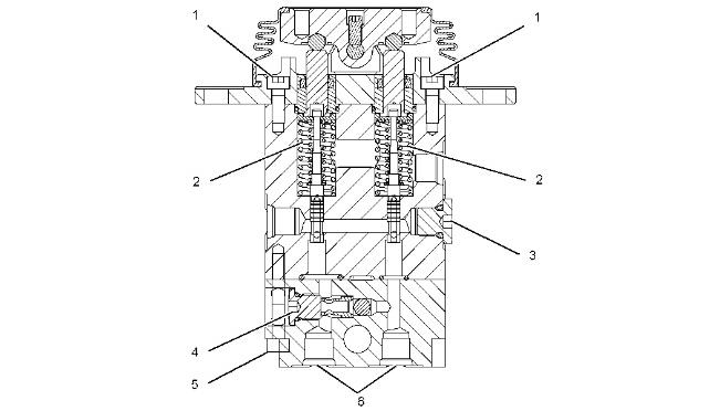
Illustration 1
Table 1
Specification for 206-3336 Pilot Valve Gp
2 2 190-7819 Spring Free length is 38.5 mm (1.52 inch).
3 1 - Torque plug to 29.4 ± 2.0 N·m (260.2 ± 17.7 lb in).
4 1 107-6479 Plug Torque to 27.0 ± 2.5 N·m (239.0 ± 22.1 lb in).
5 2 - Torque bolts to 8.8 ± 1.0 N·m (77.9 ± 8.8 lb in).
6 2 - Torque to 36.3 ± 2.0 N·m (26.8 ± 1.5 lb ft).
Removal Procedure
Table 2
Required Tools Tool
A 311-1362 Vacuum Gauge Gp 1
B - Loctite 271 -
Start By:
a. Release the hydraulic system pressure.
Personal injury can result from hydraulic oil pressure and hot oil.
Hydraulic oil pressure can remain in the hydraulic system after the engine has been stopped. Serious injury can be caused if this pressure is not released before any service is done on the hydraulic system.
Make sure all of the work tools have been lowered to the ground, and the oil is cool before removing any components or lines. Remove the oil filler cap only when the engine is stopped, and the filler cap is cool enough to touch with your bare hand.
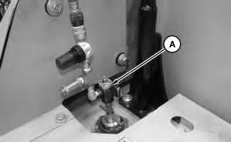
Illustration 2
1. Remove the cap from the hydraulic tank. Install Tooling (A) onto the hydraulic tank. Attach an air supply hose to Tooling (A). Apply 276 to 414 kPa (40 to 60 psi) of air. This procedure will pull vacuum on the hydraulic system.
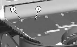
Illustration 3
2. Remove bolts (1) and plate assembly (2).
g02155365
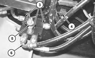
Illustration 4
g02155773
3. Disconnect harness assembly (4) and hose assemblies (6). Remove pressure switch (5) and fittings (3).
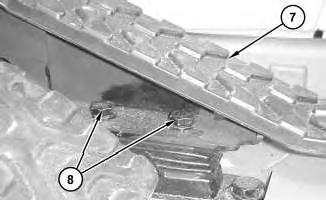
Illustration 5
4. Remove bolts (8) and pedal (7).
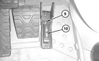
Illustration 6 g02155775
5. Remove bolts (9) and auxiliary pilot valve (10).
Installation Procedure
1. Install auxiliary pilot valve (10) in the reverse order of removal.
a. Tighten bolts (8) to a torque of 17 ± 2 N·m (150 ± 18 lb in).
b. Apply Tooling (B) to the threads of bolts (1). Copyright 1993 - 2024 Caterpillar Inc. All Rights Reserved. Private Network For SIS Licensees.
Product: EXCAVATOR
Model: 318F L EXCAVATOR HCP
Configuration: 318F L Excavator HCP00001-UP (MACHINE) POWERED BY C4.4 Engine
Disassembly and Assembly
316F, 318F Excavator Machine Systems
Media Number -UENR5585-05
Boom Bearings and Seals
SMCS - 6501-BD; 6501-SA
Removal Procedure Table 1
Required Tools
Start By:
a. Remove the boom.
When you are using hydraulic cylinders and puller studs, always ensure that the rated capacity of the puller stud meets or exceeds the rated capacity of the hydraulic cylinder. If the puller stud does not meet or exceed the rated capacity of the hydraulic cylinder, a sudden failure of the puller stud could occur. The sudden failure of the puller stud could result in personal injury or death.
1
2
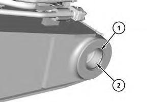
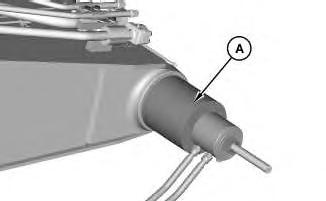
1. Remove lip seals (1).
2. Use Tooling (A) to remove sleeve bearings (2).
Installation Procedure
1. Install the sleeve bearings and the lip seals in the reverse order of removal.
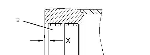

Illustration 3 g02151106
a. Install sleeve bearings (2) to Dimension (X). Dimension (X) is 9.5 ± 0.8 mm (0.37 ± 0.03 inch). Apply Tooling (C) to the inner diameter of sleeve bearings (2).
b. Use Tooling (B) in order to install lip seals (1). Apply Tooling (C) to the sealing lip of lip seals (1).
Copyright 1993 - 2024 Caterpillar Inc. All Rights Reserved. Private Network For SIS Licensees. Tue Mar 19 22:53:29 UTC+0530 2024
Product: EXCAVATOR
Model: 318F L EXCAVATOR HCP
Configuration: 318F L Excavator HCP00001-UP (MACHINE) POWERED BY C4.4 Engine
Disassembly and Assembly
316F, 318F Excavator Machine Systems
Media Number -UENR5585-05
Boom Cylinder - Lines
SMCS - 5456
Specifications
Publication Date -01/08/2015
Date Updated -14/12/2017
i04635189
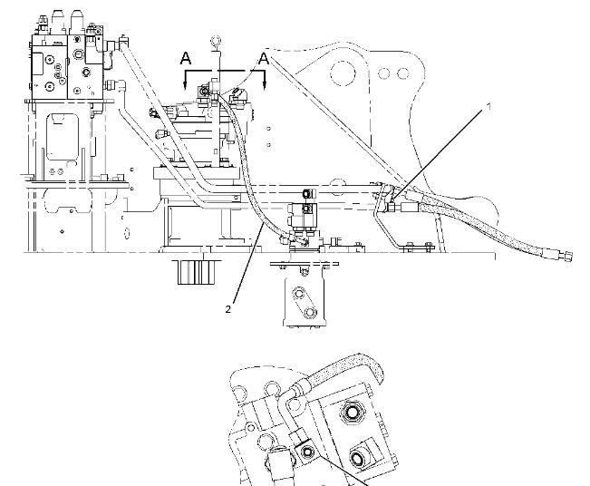

Illustration 1
side view
Description 1 1 8T-4648 Bolt Torque to 50 ± 10 N·m (37 ± 7 lb ft). 2 1 376-6273 Hose As Torque to 76 ± 4 N·m (56 ± 3 lb ft).
Product: EXCAVATOR
Model: 318F L EXCAVATOR HCP
Configuration: 318F L Excavator HCP00001-UP (MACHINE) POWERED BY C4.4 Engine
Disassembly and Assembly
316F, 318F Excavator Machine Systems
Media Number -UENR5585-05 Publication Date -01/08/2015
Boom Cylinder
SMCS - 5456
Specifications
Date Updated -14/12/2017
i04595422
Note: Callouts in the Specifications section do not match the callouts in the Removel and Install sections.
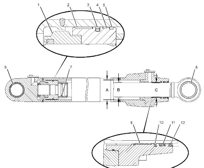
Illustration 1 g02733717
Table 1
Specification for 360-4557 Boom Cylinder Gp
Item Qty Part Number
1 1 143-8150 Special Locknut
2 1 147-5819 Ring
3 1 9X-7301 Seal As
4 1 143-8034 Ring
5 1 143-8031 Ring
Specification Description
Before assembly, apply 309-6932 Hydraulic Oil to the face and threads all around.
Torque to 4500 ± 230 N·m (3319 ± 170 lb ft).
Lubricate the inside diameter and the outside diameter with clean grease.
Lubricate the inside diameter and the outside diameter with clean grease.
Lubricate the inside diameter and the outside diameter with clean grease.
Lubricate the inside diameter and the outside diameter with clean grease.
6 1
357-5713 Bushing
7 1
8 1
A 1
B 1
266-7859 Seal Ring
240-2913 Bushing
During the press fit, insert the bushing (6) in the cap assembly with the tapered side first.
Inside diameter before assembly is 70.35 ± 0.03 mm (2.770 ± 0.001 inch).
Installation depth is 9.85 ± 0.50 mm (0.388 ± 0.020 inch).
The slit of the seal ring must turn in the direction of the piston.
Inside diameter before assembly is 80.20 ± 0.04 mm (3.157 ± 0.002 inch).
Installation depth is 10.0 ± 0.5 mm (0.39 ± 0.02 inch).
360-4571 Boom Cylinder As Bore is 110.00 ± 0.10 mm (4.331 ± 0.004 inch).
360-4569 Rod As Diameter is 79.93 ± 0.03 mm (3.147 ± 0.001 inch).
C 1 129-8068 Head
9 1 114-0755 Bushing
10 1
355-5814 Buffer Seal
Bore of head over two lands is 80.53 ± 0.03 mm (3.170 ± 0.001 inch).
Outside diameter is 85.133 ± 0.033 mm (3.3517 ± 0.0013 inch).
Thickness is 2.475 ± 0.025 mm (0.0974 ± 0.0010 inch).
Lubricate the sealing lip lightly with the lubricant that is being sealed. 11 1
355-5816 U-Cup Seal
12 1
165-9285 Lip Type Seal
13 - -
Removal Procedure
Table 2
Required Tools
Lubricate the sealing lip lightly with the lubricant that is being sealed.
Lubricate the sealing lip lightly with the lubricant that is being sealed.
Before assembly, apply green Loctite 609 to the wiper seal groove.
Tool Part Number Part Description Qty
A 311-1362 Vacuum Gauge Gp 1
B 9U-6225 Pin Driver Cap 1
C 5P-0960 Grease Cartridge 1
Personal injury can result from hydraulic oil pressure and hot oil.
Hydraulic oil pressure can remain in the hydraulic system after the engine has been stopped. Serious injury can be caused if this pressure is not released before any service is done on the hydraulic system.
Make sure all of the work tools have been lowered to the ground, and the oil is cool before removing any components or lines. Remove the oil filler cap only when the engine is stopped, and the filler cap is cool enough to touch with your bare hand.
Cylinders equipped with lock valves can remain pressurized for very long periods of time, even with the hoses removed.
Failure to relieve pressure before removing a lock valve or disassembling a cylinder can result in personal injury or death.
Ensure all pressure is relieved before removing a lock valve or disassembling a cylinder.
1. Fully extend the bucket cylinder. Fully extend the stick cylinder. Lower the boom until the stick assembly is in contact with the ground.
2. Release the pressure in the hydraulic system.
2
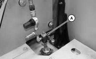
3. Install Tooling (A) onto the hydraulic tank. Attach an air supply hose onto Tooling (A). Apply 276 to 414 kPa (40 to 60 psi) of air. This procedure will pull vacuum on the hydraulic system.
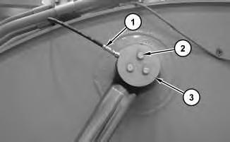
Illustration 3
4. Disconnect hose assembly (1). Remove bolts (2) and plate (3)
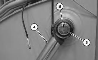
Illustration 4
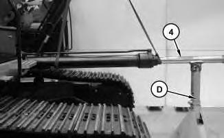
5. Install Tooling (B) in pin (5). Attach a suitable lifting device to boom cylinder (4). Use a hammer to drive pin (5) out of boom cylinder (4). The weight of boom cylinder (4) is approximately 236 kg (520 lb).
5
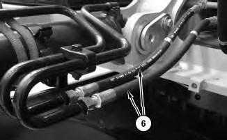
Illustration 6 g02748399
7. Disconnect hoses (6).
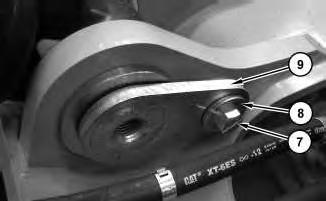
Illustration 7
8. Remove bolt (7) and washer (8). Remove pin (9).
9. Remove boom cylinder (4). The weight is approximately 236 kg (520 lb).
10. Repeat for other boom cylinder (4).
Installation Procedure
1. Install boom cylinders (4) in the reverse order of removal.
a. Lubricate pin assembly (9) with Tooling (C).
b. Lubricate pin assembly (5) with Tooling (C).
Disassembly and Assembly Table 3 Required
- Locitie 609
F 1P-0808 Multipurpose Grease -
G - Locitie 271
When you are using hydraulic cylinders and puller studs, always ensure that the rated capacity of the puller stud meets or exceeds the rated capacity of the hydraulic cylinder. If the puller stud does not meet or exceed the rated capacity of the hydraulic cylinder, a sudden failure of the puller stud could occur. The sudden failure of the puller stud could result in personal injury or death.
Cylinders equipped with lock valves can remain pressurized for very long periods of time, even with the hoses removed.
Failure to relieve pressure before removing a lock valve or disassembling a cylinder can result in personal injury or death.
Ensure all pressure is relieved before removing a lock valve or disassembling a cylinder.
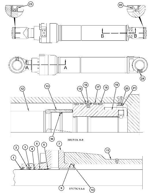
Illustration 8 g02436053
(1) Lubricate the threads and the face of piston (19). Tighten piston (19) to a torque of 8900 ± 445 N·m (6564 ± 328 lb ft).
(2) Apply Tooling (G) to the threads of setscrews (20). Tighten setscrews (20) to a torque of 56.9 ± 10.1 N·m (42 ± 7.4 lb ft).
(3) Apply Tooling (F) to inner diameter and the outer diameter of all seals.
(4) The slit of ring must be in the direction of piston.
(5) Lubricate the sealing lip with lubricant that is being sealed.
(6) Apply Tooling (E) to the wiper seal groove prior to assembly. Lubricate the sealing lip with lubricant that is being sealed.
This is the sample of the manual click on the download link for complete manual
DOWNLOAD LINK
For some reason if link does not work download this pdf and then click