DOWNLOAD LINK
For some reason if link does not work download this pdf and then click
Product: EXCAVATOR
Model: 314E LCR EXCAVATOR DKD
Configuration: 314E LCR Excavator DKD00001-UP (MACHINE) POWERED BY C4.4 Engine
Disassembly and Assembly
314E Excavator C4.4 Engine Supplement
Media Number -KENR9851-01
Publication Date -01/11/2013
Air Cleaner - Remove and Install
SMCS - 1051-010; 1054-010
Removal Procedure
Date Updated -12/11/2013
i05047930
Illustration 1
g03217438
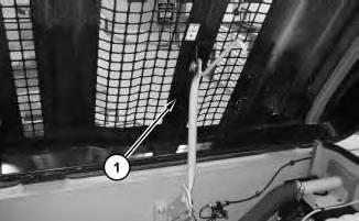
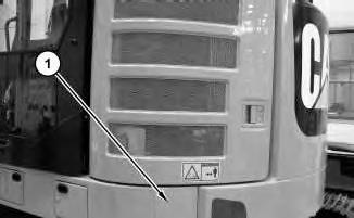
1. Open door (1) .
2
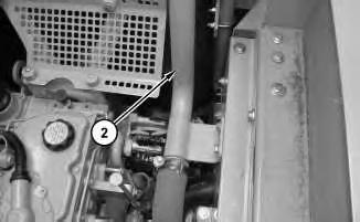
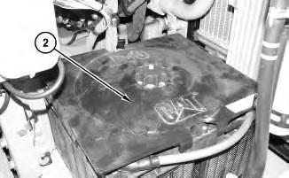
Remove tube (2) .
3
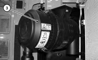
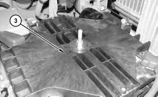
3. Remove air cleaner (3) .
Installation Procedure
1. Install air cleaner (3) in the reverse order of removal.
Copyright 1993 - 2024 Caterpillar Inc. All Rights Reserved. Private Network For SIS Licensees. Sat Mar 23 09:25:37 UTC+0530 2024
Illustration
g03217457
2.
Illustration
g03217497
Product: EXCAVATOR
Model: 314E LCR EXCAVATOR DKD
Configuration: 314E LCR Excavator DKD00001-UP (MACHINE) POWERED BY C4.4 Engine
Disassembly and Assembly
314E Excavator C4.4 Engine Supplement
Media Number -KENR9851-01 Publication Date -01/11/2013 Date Updated -12/11/2013
Alternator - Remove and Install
SMCS - 1405-010
Removal Procedure
1. Turn the battery disconnect switch to the OFF position.
1
2. Open engine hood (1) .
i05132670
Illustration
g02751140
2
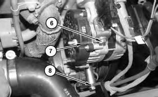
3. Disconnect tube (2) from the turbocharger. Position hose (2) out of the way.
Illustration 3
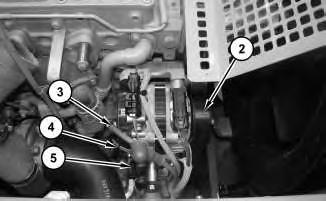
4. Remove the belt (2) for the alternator. Refer to Operation and Maintenance Manual, "BeltsInspect/Adjust/Replace".Disconnect cable assembly (3), (4) and (5) .
4
Illustration
g02751296
g02751317
Illustration
g02751378
5. Remove clamp (8). Remove bolts (6). Repeat for the bottom bolts. Remove alternator (7) .
Installation Procedure
1. Install alternator (7) in the reverse order of removal.
Copyright 1993 - 2024 Caterpillar Inc. All Rights Reserved. Private Network For SIS Licensees.
Sat Mar 23 09:16:00 UTC+0530 2024
Product: EXCAVATOR
Model: 314E LCR EXCAVATOR DKD
Configuration: 314E LCR Excavator DKD00001-UP (MACHINE) POWERED BY C4.4 Engine
Disassembly and Assembly
314E Excavator C4.4 Engine Supplement
Media Number -KENR9851-01
Publication Date -01/11/2013
Battery - Remove and Install
SMCS - 1401-010
Removal Procedure
1. Turn the battery disconnect switch to the OFF position.
Illustration 1
2. Open door and remove panel (1) .
Date Updated -12/11/2013
i05044889
g03216838
2
3
4
Illustration
g03216847
3. Remove cover (2) .
Illustration
g03216857
4. Remove cover (3) .
Illustration
g03216956
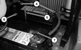
5. Disconnect battery cables (4). Remove post (5). Use two people to remove battery (6), and battery (7) .
Installation Procedure
1. Install batteries (6) and batteries (7) in the reverse order of removal.
Copyright 1993 - 2024 Caterpillar Inc. All Rights Reserved. Private Network For SIS Licensees. Sat Mar 23 09:15:36 UTC+0530 2024
Product: EXCAVATOR
Model: 314E LCR EXCAVATOR DKD
Configuration: 314E LCR Excavator DKD00001-UP (MACHINE) POWERED BY C4.4 Engine
Disassembly and Assembly
314E Excavator C4.4 Engine Supplement
Media Number -KENR9851-01
Publication Date -01/11/2013
Clean Emissions Module - Remove and Install
SMCS - 1050-010; 7279-010
Removal Procedure
1
Date Updated -12/11/2013
i05069489
Illustration
g03235919
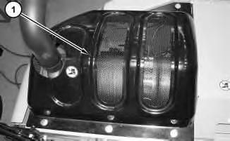
1. Remove cover (1) .
2
3
4
Illustration
g03236098
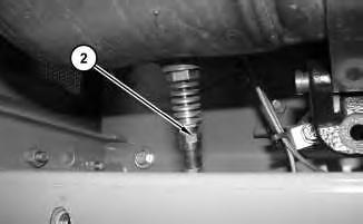
2. Disconnect soot antenna (2) .
Illustration
g03236117
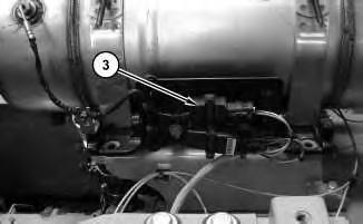
3. Disconnect harness assembly (3) .
Illustration
g03236136
4. Disconnect clamp (4). Remove bolts (5) .
5
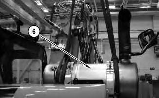
5. Attach a suitable lifting device to clean emissions module (6). The weight of clean emissions module (6) is approximately 32 kg (70 lb). Remove clean emissions module (6) .
Installation Procedure
1. Install clean emissions module (6) in the reverse order of removal.
a. Tighten soot antenna (2) to a torque of 45 ± 5 N·m (398 ± 44 lb in).
Copyright 1993 - 2024 Caterpillar Inc. All Rights Reserved. Private Network For SIS Licensees. Sat Mar 23 09:23:04 UTC+0530 2024
Product: EXCAVATOR
Model: 314E LCR EXCAVATOR DKD
Configuration: 314E LCR Excavator DKD00001-UP (MACHINE) POWERED BY C4.4 Engine
Disassembly and Assembly
314E Excavator C4.4 Engine Supplement
Media Number -KENR9851-01
Coolant Tank (Expansion) - Remove and Install
SMCS - 1354-010
Removal Procedure
At operating temperature, the engine coolant is hot and under pressure.
Steam can cause personal injury.
Check the coolant level only after the engine has been stopped and the fill cap is cool enough to touch with your bare hand.
Remove the fill cap slowly to relieve pressure.
Cooling system conditioner contains alkali. Avoid contact with the skin and eyes to prevent personal injury.
-12/11/2013
1. Refer to Operation and Maintenance Manual, "Cooling System Coolant (ELC) - Change" for the correct draining and filling procedures.
i05039509
Illustration 1
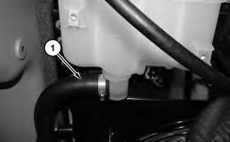
2. Disconnect hose (1) .
Illustration 2
g03210198
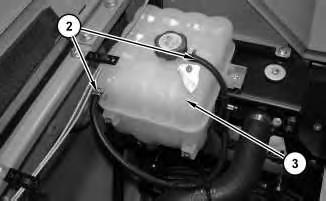
3. Disconnect hoses (2). Remove tank assembly (3) .
Installation Procedure
1. Install tank assembly (3) in the reverse order of removal.
Copyright 1993 - 2024 Caterpillar Inc. All Rights Reserved. Private Network For SIS Licensees. Sat Mar 23 09:26:39 UTC+0530 2024
g03209936
Product: EXCAVATOR
Model: 314E LCR EXCAVATOR DKD
Configuration: 314E LCR Excavator DKD00001-UP (MACHINE) POWERED BY C4.4 Engine
Disassembly and Assembly
314E Excavator C4.4 Engine Supplement
Media Number -KENR9851-01 Publication Date -01/11/2013
Date Updated -12/11/2013
Crankshaft Vibration Damper and Pulley - Remove and Install
SMCS - 1205-010
Removal Procedure
Start By:
i05034310
A. Remove the alternator belt. Refer to Disassembly and Assembly, "Alternator Belt - Remove and Install" for the correct procedure.
Illustration 1 g02449658
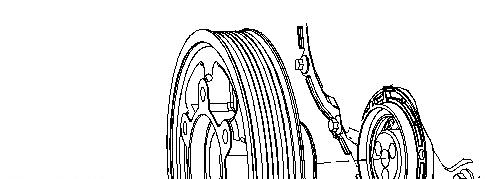
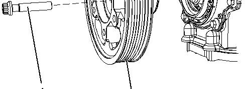
1. Use a suitable tool in order to prevent the crankshaft from rotating. Remove bolts (1) .
2. Remove crankshaft pulley (2) from the crankshaft.
Installation Procedure
Table 1
Required Tools
Tool Part Number Part Description Qty
A 8T-3052 Degree Wheel 1
1. Ensure that the pulley is clean and free from damage. Replace any components that are damaged.
2. Install a new front seal to the front cover. Refer to Disassembly and Assembly, "Crankshaft Front Seal - Remove and Install" for the correct procedure.
3. Install crankshaft pulley (2) to the crankshaft.
Note: Do not lubricate the front seal or the seal face of the crankshaft pulley.
4. Install bolts (1) .
5. Use a suitable tool in order to prevent the crankshaft from rotating. Tighten the bolts to a torque of 22 N·m (195 lb in).
6. Use tooling (A) in order to turn bolts (1) through an additional 120 degrees.
Mar 23 09:28:15 UTC+0530 2024
Product: EXCAVATOR
Model: 314E LCR EXCAVATOR DKD
Configuration: 314E LCR Excavator DKD00001-UP (MACHINE) POWERED BY C4.4 Engine
Disassembly and Assembly
314E Excavator C4.4 Engine Supplement
Media Number -KENR9851-01 Publication Date -01/11/2013 Date Updated -12/11/2013
Electric Starting Motor - Remove and Install
SMCS - 1453-010
Removal Procedure
1. Turn the battery disconnect switch to the OFF position.
1
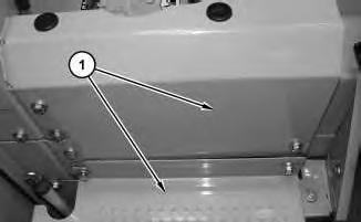
2. Remove guards (1) .
i05036272
Illustration
g03207356
Illustration 2
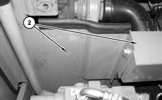
3. Remove guards (2) .
Illustration 3
g03207459
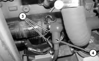
4. Disconnect harness assemblies (3) and cable (4) .
Illustration 4
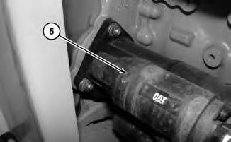
5. Remove electric starting motor (5) .
g03207577
g03207416
Installation Procedure
1. Install electric starting motor (5) in the reverse order of removal.
Copyright 1993 - 2024 Caterpillar Inc. All Rights Reserved. Private Network For SIS Licensees. Sat Mar 23 09:16:18 UTC+0530 2024
Product: EXCAVATOR
Model: 314E LCR EXCAVATOR DKD
Configuration: 314E LCR Excavator DKD00001-UP (MACHINE) POWERED BY C4.4 Engine
Disassembly and Assembly
314E Excavator C4.4 Engine Supplement
Media Number -KENR9851-01
Engine - Remove and Install
SMCS - 1000-010
Removal Procedure
Start By:
A. Remove hood.
B. Remove counterweight.
C. Remove Clean Emissions Module
D. Remove fan and fan guard.
-12/11/2013 i05034333
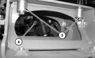
1. Drain Coolant. Refer to Operation and Maintenance Manual, "Cooling System Coolant (ELC) - Change" for the correct draining and filling procedures.
2. Drain engine oil. Refer to Operation and Maintenance Manual, "Engine Oil - Change". Refer to Operation and Maintenance Manual, "Engine Oil - Check" for the correct draining and filling procedure.
3. Remove fan belt. Refer to Disassembly and Assembly, "Belt - Inspect/Adjust/Replace".
Illustration 1
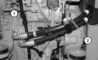
4. Disconnect hose assemblies (1). Disconnect bracket (2). Remove hose assemblies (1) .
Illustration 2
g03204781
5. Disconnect harness assembly (3). Disconnect fuel lines (4) .
Illustration 3
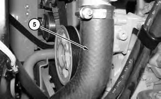
6. Remove hose (5) .
g03204789
4
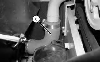
7. Remove hose (6) .
Illustration 5
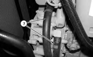
8. Disconnect hose assemblies (7) .
Illustration 6
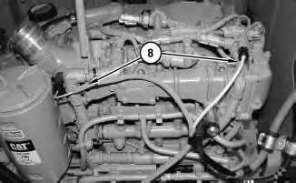
9. Disconnect harness assemblies (8) .
Illustration
g03204876
g03204899
g03204902
7
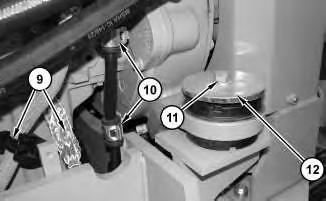
10. Remove cable assembly and clip (9). Disconnect clips (10). Remove motor mount bolt (11) and upper pads (12) .
8
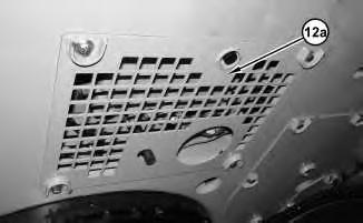
11. Remove bottom cover (12a) .
Illustration
g03204919
Illustration
g03301076
Illustration 9 g03204956
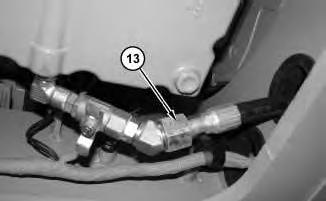
12. Disconnect hose assembly (13).
Illustration 10
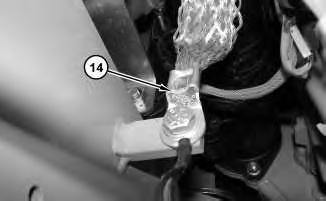
13. Disconnect ground strap (14) .
11
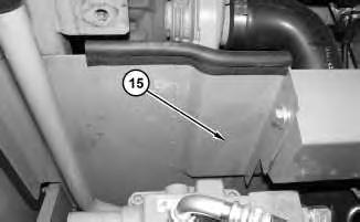
14. Remove panel assembly (15) .
g03204961
Illustration
g03206099
This is the sample of the manual click on the download link for complete manual