DOWNLOAD LINK
For some reason if link does not work download this pdf and then click
Product: EXCAVATOR
Model: 314D LCR EXCAVATOR XHR
Configuration: 314D CR & 314D LCR Excavator XHR00001-UP (MACHINE) POWERED BY C4.2 Engine
Disassembly and Assembly
314D CR Hydraulic Excavator
C4.2 Engine Supplement
Media Number -KENR6403-02 Publication Date -01/03/2010 Date Updated -23/03/2010
i03176622
Aftercooler - Remove
SMCS - 1063-011
Removal Procedure
Start By:
A. Remove the radiator and the aftercooler. Refer to Disassembly and Assembly, "Radiator and Aftercooler - Remove".
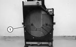
Illustration 1
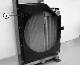
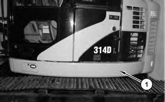
1. Remove fan guard (1) .
g01624434
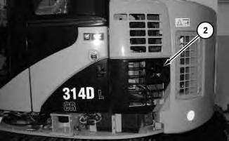
2
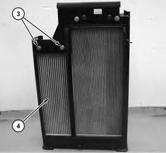
2. Remove fan shroud (2) .
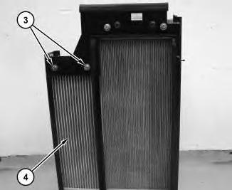
3
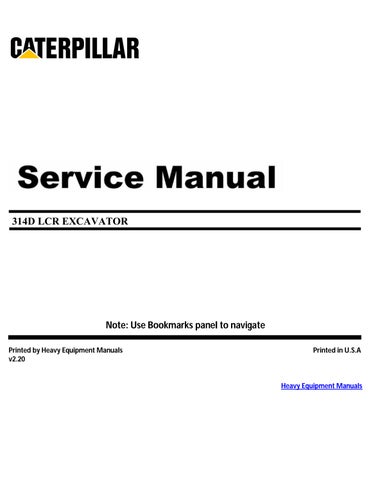
3. Remove bolts (3). Remove aftercooler (4) .
Copyright 1993 - 2024 Caterpillar Inc. All Rights Reserved. Private Network For SIS Licensees.
Wed May 15 12:09:10 UTC+0530 2024
Illustration
g01624440
Illustration
g01624701
Product: EXCAVATOR
Model: 314D LCR EXCAVATOR XHR
Configuration: 314D CR & 314D LCR Excavator XHR00001-UP (MACHINE) POWERED BY C4.2 Engine
Disassembly and Assembly
314D CR Hydraulic Excavator
C4.2 Engine Supplement
Media Number -KENR6403-02
Air Cleaner - Remove and Install
SMCS - 1051-010; 1054-010
Removal Procedure
1. Open the left, rear door on the machine.
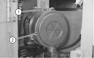
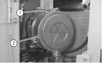
Illustration 1
g00956168
2. Release three clips (1) and remove cover assembly (2) .
-23/03/2010
i01878814
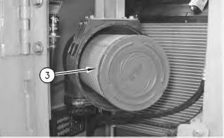
2
3. Remove primary element (3) and remove the secondary element.
3
.
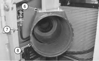
Illustration 4
5. Remove bolts (6). Disconnect hose (7). Remove air cleaner housing (8) .
Illustration
g00956170
Illustration
g00956172
4. Loosen hose clamp (4) and remove hose (5)
g00956173
Installation Procedure
5
1. Position air cleaner housing (8) on the machine. Install bolts (6). Connect hose (7) .
Illustration 6
2. Connect hose (5) to the air cleaner housing. Tighten clamp (4) .
Illustration
g00956173
g00956172
Illustration 7
3. Install the secondary element and install primary element (3) .
Illustration 8
g00956168
4. Install cover assembly (2) and engage clips (1) .
5. Close the left, rear door. Copyright 1993 - 2024 Caterpillar Inc. All Rights Reserved. Private Network For SIS Licensees.
Wed May 15 12:08:38 UTC+0530 2024
g00956170
Product: EXCAVATOR
Model: 314D LCR EXCAVATOR XHR
Configuration: 314D CR & 314D LCR Excavator XHR00001-UP (MACHINE) POWERED BY C4.2 Engine
Disassembly and Assembly
314D CR Hydraulic Excavator
C4.2 Engine Supplement Media Number -KENR6403-02
Alternator - Remove and Install
SMCS - 1405-010
Removal Procedure
Start By:
i01878429
A. Remove the counterweight. Refer to Disassembly and Assembly, "Counterweight - Remove and Install".
Accidental machine starting can cause injury or death to personnel working on the machine.
To avoid accidental machine starting, turn the battery disconnect switch to the OFF position and remove the key. If the machine is not equipped with a battery disconnect switch, disconnect the battery cables from the battery and tape the battery clamps.
Place a do not operate tag at the battery disconnect switch location to inform personnel that the machine is being worked on.
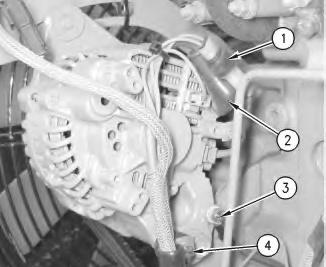
1
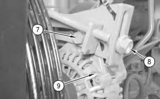
1. Disconnect harness assemblies (1).
2. Raise cover (2). Remove the nut and harness assembly.
3. Remove bolt (3) and harness assemblies.
4. Remove bolt (4) and the spacer.
2
Illustration
g00955978
Illustration
g00955983
3
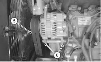
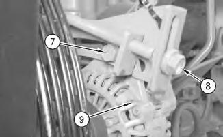
5. Loosen bolts (6), (7), and (8) .
6. Remove belts (5) .
7. Remove bolts (6) and the spacers.
8. Remove bolt (7) and alternator (9) .
Installation Procedure
4
Illustration
g00955985
Illustration
g00955985
5
1. Position alternator (9) and install bolt (7) .
2. Install bolts (6) and the spacers.
3. Install belts (5). Refer to Disassembly and Assembly, "Belt - Inspect/Adjust/Replace".
4. Tighten bolts (6), (7), and (8) .
6
5. Install bolt (4) and the spacer.
6. Install harness assemblies and bolt (3) .
7. Install the harness assembly and the nut. Lower cover (2) .
8. Connect harness assemblies (1).
Illustration
g00955983
Illustration
g00955978
End By: Install the counterweight. Refer to Disassembly and Assembly, "CounterweightRemove and Install".
Copyright 1993 - 2024 Caterpillar Inc. All Rights Reserved.
Private Network For SIS Licensees.
Wed May 15 12:03:25 UTC+0530 2024
Product: EXCAVATOR
Model: 314D LCR EXCAVATOR XHR
Configuration: 314D CR & 314D LCR Excavator XHR00001-UP (MACHINE) POWERED BY C4.2 Engine
Disassembly and Assembly
314D CR Hydraulic Excavator C4.2 Engine Supplement
i03110723
Battery - Remove and Install
SMCS - 1401-010
Removal Procedure
1. Turn the battery disconnect switch to the OFF position.
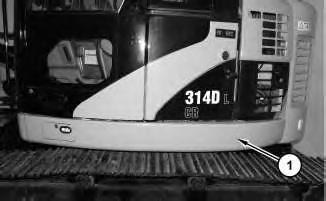
Illustration 1
2. Remove guard assembly (1) .
g01589968
Illustration 2
3. Open access door (2) on the left side of the machine.
Illustration 3
g01589980
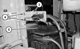
4. Remove bolts (4). Reposition bracket (3) and the cables. Remove cover (5) .
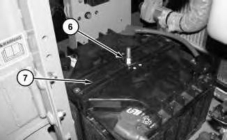
Illustration 4
5. Remove nut (6) and cover (7) .
g01597165
g01589984
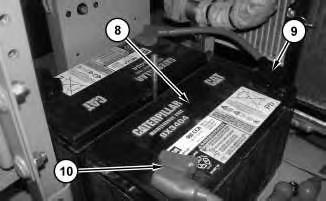
5
6. Disconnect negative battery cable (9). Disconnect positive battery cable (10). Use two people to remove battery (8) .
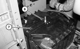
6
7. Remove nut (15) that is located under the upper body. Remove rod (12) .
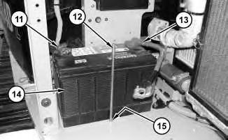
8. Disconnect negative battery cable (11). Disconnect positive battery cable (13). Use two people to remove battery (14) .
Installation Procedure
Illustration
g01598114
Illustration
g01597167
1. Use two people to position battery (14) in the machine. Connect positive battery cable (13). Connect negative battery cable (11) .
2. Install rod (12) and nut (15) that is located under the carbody.
8
3. Use two people to position battery (8) in the machine. Connect positive battery cable (10). Connect negative battery cable (9).
Illustration 7
g01597167
Illustration
g01598114
Illustration 9
4. Install cover (7) and nut (6) .
Illustration 10
g01589980
5. Install cover (5). Position bracket (3) and the cables. Install bolts (4) .
Illustration 11
6. Close access door (2) on the left side of the machine.
g01597165
g01589984
7. Install guard assembly (1) .
8. Turn the battery disconnect switch to the ON position.
Copyright 1993 - 2024 Caterpillar Inc. All Rights Reserved. Private Network For SIS Licensees.
Wed May 15 12:03:02 UTC+0530 2024
Product: EXCAVATOR
Model: 314D LCR EXCAVATOR XHR
Configuration: 314D CR & 314D LCR Excavator XHR00001-UP (MACHINE) POWERED BY C4.2 Engine
Disassembly and Assembly
314D CR Hydraulic Excavator
C4.2 Engine Supplement
Coolant Tank (Expansion) - Remove and Install
SMCS - 1354-010
Removal Procedure
NOTICE
Care must be taken to ensure that fluids are contained during performance of inspection, maintenance, testing, adjusting and repair of the product. Be prepared to collect the fluid with suitable containers before opening any compartment or disassembling any component containing fluids.
Refer to Special Publication, NENG2500, "Caterpillar Dealer Service Tool Catalog" for tools and supplies suitable to collect and contain fluids on Caterpillar products.
Dispose of all fluids according to local regulations and mandates.
i03164820
At operating temperature, the engine coolant is hot and under pressure.
Steam can cause personal injury.
Check the coolant level only after the engine has been stopped and the fill cap is cool enough to touch with your bare hand.
Remove the fill cap slowly to relieve pressure.
Cooling system conditioner contains alkali. Avoid contact with the skin and eyes to prevent personal injury.
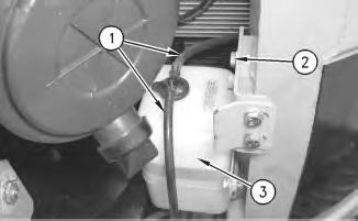
1
1. Disconnect two hoses (1) from the cap on the reserve tank assembly.
2. Remove bolts (2) .
3. Remove reserve tank assembly (3) .
Installation Procedure
Illustration 2
1. Position reserve tank assembly (3) on the machine.
2. Install bolts (2) .
3. Connect two hoses (1) .
Illustration
g00956190
g00956190
4. Check the coolant level. Refer to Operation and Maintenance Manual, "Cooling System Level - Check".
Copyright 1993 - 2024 Caterpillar Inc. All Rights Reserved. Private Network For SIS Licensees.
Wed May 15 12:10:30 UTC+0530 2024
Product: EXCAVATOR
Model: 314D LCR EXCAVATOR XHR
Configuration: 314D CR & 314D LCR Excavator XHR00001-UP (MACHINE) POWERED BY C4.2 Engine
Disassembly and Assembly
314D CR Hydraulic Excavator
C4.2 Engine Supplement
Media Number -KENR6403-02 Publication Date -01/03/2010 Date Updated -23/03/2010
i01893225
Crankshaft Vibration Damper and Pulley - Remove and Install
SMCS - 1205-010
Removal Procedure
Table 1
Required Tools
A 1P-2321 Combination Puller 1
Start By:
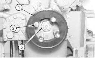
A. Remove the V-belts. Refer to Disassembly and Assembly, "V-Belts - Remove and Install". Illustration 1
The engine has been removed for photographic purposes.
1. Remove bolts (2). Remove pulley (1). Remove nut (3) .
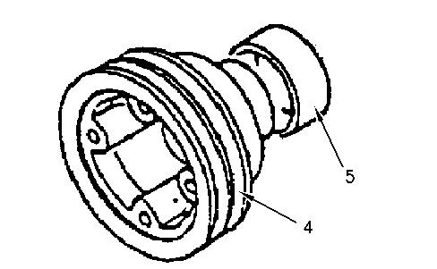
Illustration 2 g00985496
The engine has been removed for photographic purposes.
2. Use Tooling (A) and remove crankshaft pulley (4) from the engine.
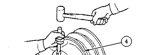
Illustration 3 g00985500
3. If it is necessary to remove wear sleeve (5) from crankshaft pulley (4), use a hammer and a chisel. Hold the chisel at right angles to the surface of the wear sleeve. Tap the wear sleeve in three places. You can remove the wear sleeve once the tension is released.