Note: Use Bookmarks panel to navigate
Product: EXCAVATOR
Model: 314D LCR EXCAVATOR SBP
Configuration: 314D LCR Excavator SBP00001-UP (MACHINE) POWERED BY C4.2 Engine
Disassembly and Assembly
314D CR Hydraulic Excavator
C4.2 Engine Supplement
i03138352
Engine - Remove
SMCS - 1000-011
Removal Procedure
Table 1
Required Tools
Start By:
A. Remove the counterweight. Refer to Disassembly and Assembly, "Counterweight - Remove and Install".
B. Remove the hood. Refer to Disassembly and Assembly, "Hood - Remove and Install".
C. Remove the fan. Refer to Disassembly and Assembly, "Fan - Remove and Install".
Hot oil and hot components can cause personal injury. Do not allow hot oil or hot components to contact skin. At operating temperature, the engine coolant is hot and under pressure. Steam can cause personal injury.
Check the coolant level only after the engine has been stopped and the cooling system pressure cap is cool enough to touch with your bare hand.
Remove the cooling system pressure cap slowly to relieve pressure.
Cooling system conditioner contains alkali. Avoid contact with the skin and eyes to prevent personal injury.
Accidental machine starting can cause injury or death to personnel working on the machine.
To avoid accidental machine starting, turn the battery disconnect switch to the OFF position and remove the key. If the machine is not equipped with a battery disconnect switch, disconnect the battery cables from the battery and tape the battery clamps.
Place a do not operate tag at the battery disconnect switch location to inform personnel that the machine is being worked on.
NOTICE
Care must be taken to ensure that fluids are contained during performance of inspection, maintenance, testing, adjusting and repair of the product. Be prepared to collect the fluid with suitable containers before opening any compartment or disassembling any component containing fluids.
Refer to Special Publication, NENG2500, "Caterpillar Dealer Service Tool Catalog" for tools and supplies suitable to collect and contain fluids on Caterpillar products.
Dispose of all fluids according to local regulations and mandates.
Note: Put identification marks on all hoses, on all hose assemblies, on all wires, and on all tube assemblies for installation purposes. Plug all hose assemblies and all tube assemblies. This helps to prevent fluid loss, and this helps to keep contaminants from entering the system.
1. Drain the coolant from the coolant system into a container for storage or for disposal. Refer to Operation and Maintenance Manual, "Cooling System Coolant (ELC) - Change" for the proper draining procedure. Refer to Operation and Maintenance Manual, "Capacities (Refill)" for the proper amount.
2. Turn the battery disconnect switch to the OFF position.
1
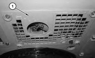
3. Remove bottom guard (1) .
2
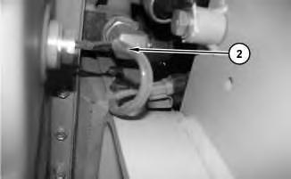
4. Disconnect harness assembly (2) .
Illustration
g01615564
Illustration
g01615566
This is the sample of the manual click on the download link for complete manual
DOWNLOAD LINK
For some reason if link does not work download this pdf and then click
Illustration 3
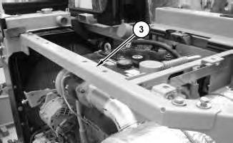
5. Remove support (3) .
Illustration 4
g01615734
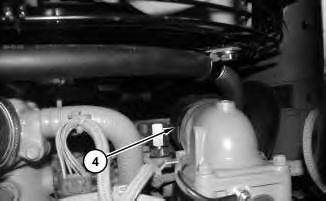
6. Loosen the clamp and disconnect hose (4) .
Illustration 5
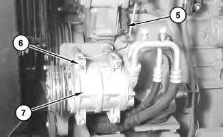
7. Disconnect harness assembly (5). Remove harness assembly (5) from the bracket. Remove bolts (6) and move refrigerant compressor (7) out of the way.
g01615653
g01615755
6
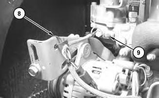
8. Disconnect harness assembly (9). Cut cable straps (8) .
Illustration 7
g01619345
9. Disconnect harness assemblies (10). Raise the cover and disconnect harness assembly (11). Remove bolt (13) and the spacer. Remove bolt (12) .
8
Illustration
g01619342
Illustration
g01619356
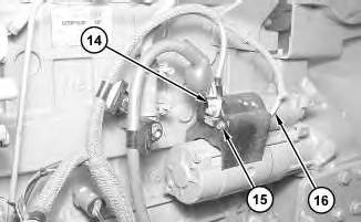
10. Raise the cover and disconnect cable assembly (14). Remove bolt (15) and the cover. Disconnect harness assembly (16) .
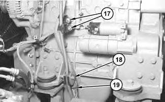
11. Remove bolts (17) and the spacers. Cut cable strap (19). Disconnect the harness assembly. Remove bolt (18) and position the harness assemblies out of the way.
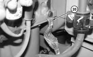
12. Disconnect ground strap (20) .
Illustration 9
g01619365
Illustration 10
g01615534
11
12
13
Illustration
g01619395
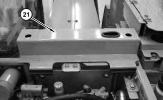
13. Open housing (21) for the condenser.
Illustration
g01619433
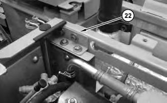
14. Remove support (22) .
Illustration
g01619434
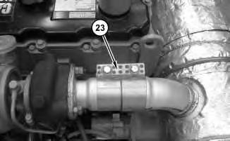
15. Loosen clamp (23) and slide clamp (23) to the left side.
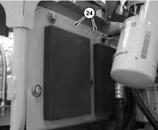
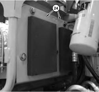
16. Remove upper panels (24) .
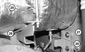
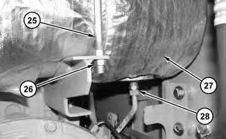
17. Disconnect drain tube (28) .
18. Remove nut (26). Remove U-bolt assembly (25). .
19. Repeat Step 18 for the remaining two U-bolt assemblies. Remove muffler (27) .
Illustration 14
g01619435
Illustration 15
g01619452
16
g01619436
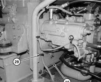
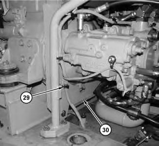
20. Remove clips (29). Remove lower panel (30) .
Illustration 17
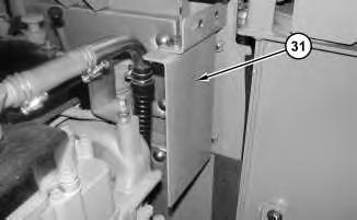
21. Remove panel (31) .
g01619495
Illustration
18
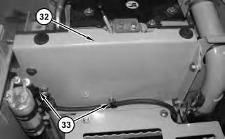
Remove clips (33). Remove panel assembly (32) .
Illustration
g01619496
22.
Illustration 19
g01619497
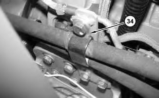
23. Remove clip (34) .
Illustration 20
g01619531
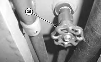
24. Fuel valve (35) is located under the fuel tank. Close fuel valve (35) .
21
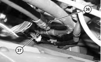
Disconnect hose assemblies (36) and (37) .
22
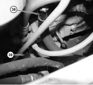
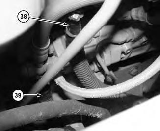
26. Disconnect fuel line (38). Disconnect return-to-tank fuel line (39) .
Illustration
g01619541
25.
Illustration
g01619542
Illustration 23
g01619551
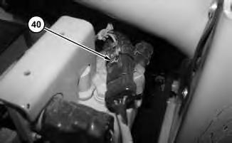
27. Disconnect harness assembly (40) .
Illustration 24
g01619738
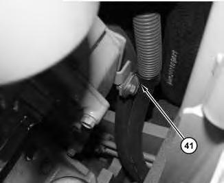
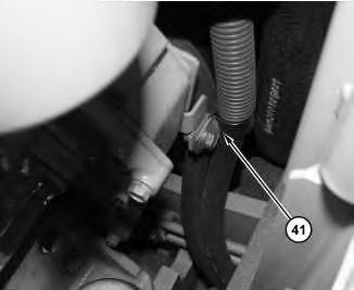
28. Disconnect clip (41) .
Illustration 25
g01619740
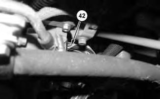
29. Disconnect harness assembly (42) .
Illustration 26
g01619748
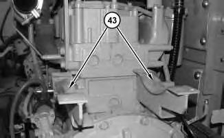
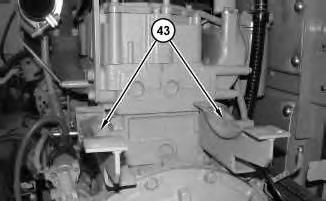
30. Remove muffler mounting brackets (43) .
Illustration 27
g01619749
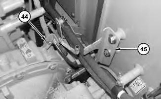
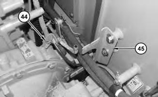
31. Disconnect harness assembly (44). Remove bracket (45) .
Illustration 28
g01619751
Illustration 29
g01619754
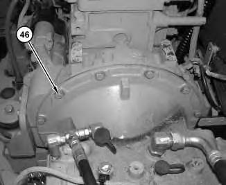
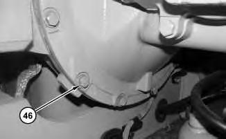
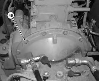
32. Remove bolts (46) .
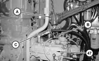
33. Remove the bolt and replace the bolt with Tooling (B) and Tooling (C). Use Tooling (A), tooling (B), and tooling (C) to support main hydraulic pump (47) .
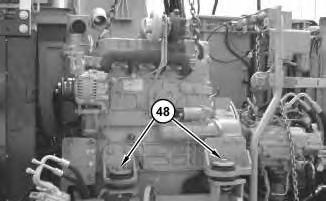
34. Attach a suitable lifting device to the engine. The weight of the engine is approximately 411 kg (907 lb). Remove engine mounting bolts (48) .
Illustration 30
g01619769
Illustration 31
g01619795
Illustration 32
g01619801
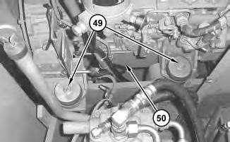
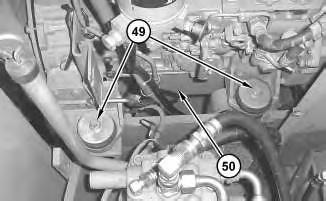
35. Remove engine mounting bolts (49) and remove the engine. The weight of engine (50) is approximately 411 kg (907 lb).
Copyright 1993 - 2024 Caterpillar Inc. All Rights Reserved. Private Network For SIS Licensees.
Fri Feb 16 00:44:52 UTC+0530 2024
Product: EXCAVATOR
Model: 314D LCR EXCAVATOR SBP
Configuration: 314D LCR Excavator SBP00001-UP (MACHINE) POWERED BY C4.2 Engine
Disassembly and Assembly
314D CR Hydraulic Excavator
C4.2 Engine Supplement
Engine - Install
SMCS - 1000-012
Installation Procedure
Table 1
Required Tools Tool
Hot oil and hot components can cause personal injury. Do not allow hot oil or hot components to contact skin.
At operating temperature, the engine coolant is hot and under pressure.
Steam can cause personal injury.
Check the coolant level only after the engine has been stopped and the cooling system pressure cap is cool enough to touch with your bare hand.
Remove the cooling system pressure cap slowly to relieve pressure.
Cooling system conditioner contains alkali. Avoid contact with the skin and eyes to prevent personal injury.
i03257745
Accidental machine starting can cause injury or death to personnel working on the machine.
To avoid accidental machine starting, turn the battery disconnect switch to the OFF position and remove the key. If the machine is not equipped with a battery disconnect switch, disconnect the battery cables from the battery and tape the battery clamps.
Place a do not operate tag at the battery disconnect switch location to inform personnel that the machine is being worked on.
NOTICE
Care must be taken to ensure that fluids are contained during performance of inspection, maintenance, testing, adjusting and repair of the product. Be prepared to collect the fluid with suitable containers before opening any compartment or disassembling any component containing fluids.
Refer to Special Publication, NENG2500, "Caterpillar Dealer Service Tool Catalog" for tools and supplies suitable to collect and contain fluids on Caterpillar products.
Dispose of all fluids according to local regulations and mandates.
1. Attach a suitable lifting device to the engine. The weight of the engine is approximately 411 kg (907 lb). Install engine mounting bolts (48) .
2
2. Install engine mounting bolts (49) .
Illustration 3
3. Slide Hydraulic pump (47) into rear of engine by using tooling (A) , tooling (B), and tooling (C).
Illustration
g01619801
g01619769
4
5
4. Install bolts (46) in order to connect the pump to the engine.
Illustration
g01619754
Illustration
g01619751
Illustration 6
5. Install bracket assembly (45). Install harness assembly (44) .
7
6. Install muffler brackets (43) .
8
7. Connect harness assembly (42) .
Illustration
g01619748
Illustration
g01619740
9
10
Illustration
g01619738
8. Connect clip (41) .
Illustration
g01619551
9. Connect harness assembly (40) .
11
10. Connect fuel line (38). Connect return-to-tank fuel line (39) .
Illustration 12
11. Connect hose assemblies (36 ) and (37) .
Illustration
g01619542
g01619541
13
Illustration
g01619531
12. Open fuel valve (35). The fuel valve is located under the fuel tank.
Illustration 14
g01619497
13. Install clip (34) .
Illustration 15
g01619496
14. Install panel (32). Install clips (33) .
Illustration 16
g01619495
15. Install panel (31) .
Illustration 17
g01619436
16. Install lower panel (30). Install clips (29) .
18
17. Position muffler (27) on the brackets. Connect drain tube (28). Install U-bolts (25) on muffler assembly and tighten nuts (26) .
19
18. Install upper panels (24) .
Illustration
g01619452
Illustration
g01619435
This is the sample of the manual click on the download link for complete manual