


Product: EXCAVATOR
Model: 314C EXCAVATOR PCA
Configuration: 314C CR & 314C LCR Excavators PCA00001-UP (MACHINE) POWERED BY 3064 Engine
Disassembly and Assembly 314C ExcavatorEngine Supplement
-RENR6604-03
Air Cleaner - Remove and Install
SMCS - 1051-010; 1054-010
Removal Procedure
1. Open the left, rear door on the machine.
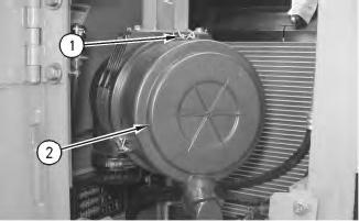
Illustration 1 g00956168
2. Release three clips (1) and remove cover assembly (2) .
i01878814
2
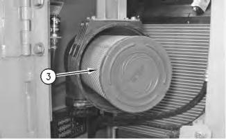
3. Remove primary element (3) and remove the secondary element.
3
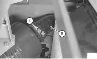
.
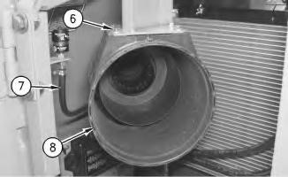
Illustration 4 g00956173
5. Remove bolts (6). Disconnect hose (7). Remove air cleaner housing (8) .
Installation Procedure
Illustration 5
1. Position air cleaner housing (8) on the machine. Install bolts (6). Connect hose (7) .
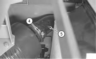
Illustration 6
2. Connect hose (5) to the air cleaner housing. Tighten clamp (4) .
Illustration 7
3. Install the secondary element and install primary element (3) .
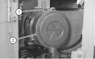
Illustration 8
4. Install cover assembly (2) and engage clips (1) .
5. Close the left, rear door.
Copyright 1993 - 2019 Caterpillar Inc. All Rights Reserved. Private Network For SIS Licensees. Sat Oct 26 10:06:24 UTC+0530 2019
Product: EXCAVATOR
Model: 314C EXCAVATOR PCA
Configuration: 314C CR & 314C LCR Excavators PCA00001-UP (MACHINE) POWERED BY 3064 Engine
Disassembly and Assembly 314C ExcavatorEngine Supplement
Air Conditioner Dryer - Remove and Install
SMCS - 7322-010
Removal Procedure
Table 1 Required Tools
i01878519
Note: SERVICE DATA: TOOLING (ZZ) WILL NOT BE IDENTIFIED IN PHOTOGRAPHS IN THE REMOVAL OR THE INSTALLATION. THIS TOOLING IS SHOWN IN ORDER TO ASSIST THE EXPERIENCED SERVICEMAN.
NOTICE
Effective July 1, 1992 regulations prohibit the venting of any refrigerant into the atmosphere. Refer to Caterpillar publications Service Manuals, SENR3334, SENR5664, and NEDG5065 for the proper procedure, the proper equipment, and the proper tools needed in order to reclaim refrigerant from any Caterpillar equipment.
This is the sample of the manual click on the download link for complete manual
DOWNLOAD LINK
For some reason if link does not work download this pdf and then click
Personal injury can result from contact with refrigerant.
Contact with refrigerant can cause frost bite. Keep face and hands away to help prevent injury.
Protective goggles must always be worn when refrigerant lines are opened, even if the gauges indicate the system is empty of refrigerant.
Always use precaution when a fitting is removed. Slowly loosen the fitting. If the system is still under pressure, release it slowly in a well ventilated area.
Personal injury or death can result from inhaling refrigerant through a lit cigarette.
Inhaling air conditioner refrigerant gas through a lit cigarette or other smoking method or inhaling fumes released from a flame contacting air conditioner refrigerant gas, can cause bodily harm or death.
Do not smoke when servicing air conditioners or wherever refrigerant gas may be present.
Use a certified recovery and recycling cart to properly remove the refrigerant from the air conditioning system.
1. Open the engine access door on the left side of the machine.
2. Recover the air conditioner refrigerant from the air conditioner system. Refer to Service Manual, SENR5664, "Air Conditioning and Heating Systems with R-134a Refrigerant" and Special Publication, NEDG5065, "Air Conditioning Tools" for detailed information about evacuating the air conditioning system of any Caterpillar machine.
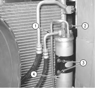
Illustration 1 g00956120
The air cleaner and the elements have been removed for photographic purposes.
3. Disconnect hose assemblies (1) and (2).
4. Remove bolts (3), and remove receiver-dryer assembly (4) .
Installation Procedure
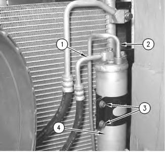
1. Position receiver-dryer assembly (4) into the straps.
2. Install bolts (3) in order to secure receiver-dryer assembly (4) .
3. Connect hose assemblies (1) and (2) .
4. Charge the air conditioner system. The correct charge is 0.9979 kg (2.2 lb). Refer to Service Manual, SENR5664, "Air Conditioning and Heating Systems with R-134a Refrigerant" for the correct procedure. Refer to Special Publication, NEDG5065, "Air Conditioning Tools" for the correct tools.
5. Close the engine access door on the left side of the machine. Copyright 1993 - 2019 Caterpillar Inc.
Rights Reserved.
Network For SIS Licensees.
Product: EXCAVATOR
Model: 314C EXCAVATOR PCA
Configuration: 314C CR & 314C LCR Excavators PCA00001-UP (MACHINE) POWERED BY 3064 Engine
Disassembly and Assembly 314C ExcavatorEngine Supplement Media Number -RENR6604-03
Air Inlet Heater - Remove and Install
SMCS - 1090-010
Removal Procedure
Hot engine components can cause injury from burns. Before performing maintenance on the engine, allow the engine and the components to cool.
Updated -10/11/2008
i01884276
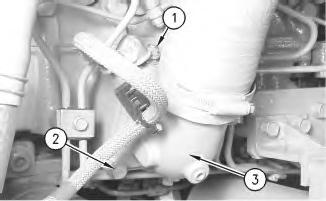
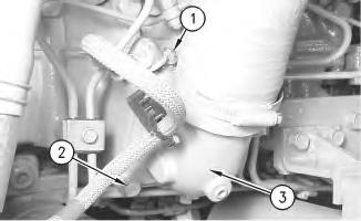
1. Slide the rubber boot off the harness assembly and remove nut (1). Remove the harness assembly from the stud.
2. Remove bolts (2) and carefully lift elbow assembly (3) from the air inlet heater.
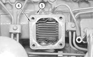
Illustration 2
3. Remove gasket (4) and remove air inlet heater (5) .
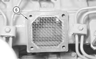
Illustration 3
4. Remove gasket (6) which is located under the air inlet heater.
Installation Procedure
Note: Check all gaskets for wear or for damage. Replace the gaskets, if necessary.
4
1. Place gasket (6) on the inlet manifold.
5
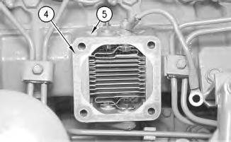
2. Install air inlet heater (5) and install gasket (4) .
3. Install elbow assembly (3) and secure the elbow assembly with bolts (2). Make sure that the ground wire is connected to one of the bolts.
4. Install the harness assembly on the stud and tighten nut (1). Slide the rubber boot over the harness assembly.
Product: EXCAVATOR
Model: 314C EXCAVATOR PCA
Configuration: 314C CR & 314C LCR Excavators PCA00001-UP (MACHINE) POWERED BY 3064 Engine
Disassembly and Assembly 314C ExcavatorEngine Supplement
Alternator - Remove and Install
SMCS - 1405-010
Removal Procedure
Start By:
A. Remove the counterweight. Refer to Disassembly and Assembly, "Counterweight - Remove and Install".
Accidental machine starting can cause injury or death to personnel working on the machine.
To avoid accidental machine starting, turn the battery disconnect switch to the OFF position and remove the key. If the machine is not equipped with a battery disconnect switch, disconnect the battery cables from the battery and tape the battery clamps.
Place a do not operate tag at the battery disconnect switch location to inform personnel that the machine is being worked on.
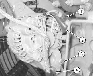
Illustration 1
1. Disconnect harness assemblies (1).
2. Raise cover (2). Remove the nut and harness assembly.
3. Remove bolt (3) and harness assemblies.
4. Remove bolt (4) and the spacer.
2
3
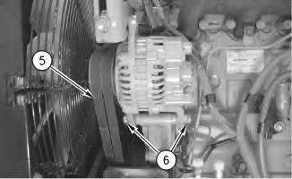
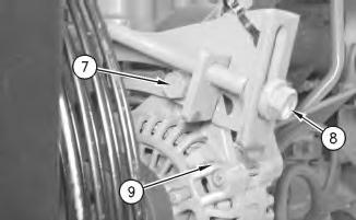
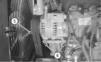
5. Loosen bolts (6), (7), and (8) .
6. Remove belts (5) .
7. Remove bolts (6) and the spacers.
8. Remove bolt (7) and alternator (9) .
Installation Procedure
4
5
1. Position alternator (9) and install bolt (7) .
2. Install bolts (6) and the spacers.
3. Install belts (5). Refer to Disassembly and Assembly, "Belt - Inspect/Adjust/Replace".
4. Tighten bolts (6), (7), and (8) .
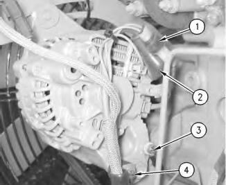
Illustration 6
5. Install bolt (4) and the spacer.
6. Install harness assemblies and bolt (3) .
7. Install the harness assembly and the nut. Lower cover (2) .
8. Connect harness assemblies (1).
End By: Install the counterweight. Refer to Disassembly and Assembly, "Counterweight - Remove and Install". Copyright 1993 - 2019 Caterpillar Inc.
Product: EXCAVATOR
Model: 314C EXCAVATOR PCA
Configuration: 314C CR & 314C LCR Excavators PCA00001-UP (MACHINE) POWERED BY 3064 Engine
Disassembly and Assembly 314C ExcavatorEngine Supplement Media Number -RENR6604-03
Crankshaft
Vibration
SMCS - 1205-010
Removal Procedure
Table 1
Required Tools
i01893225
Damper and Pulley - Remove and Install
A 1P-2321 Combination Puller 1
Start By:
A. Remove the V-belts. Refer to Disassembly and Assembly, "V-Belts - Remove and Install".
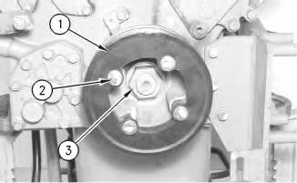
Illustration 1 g00985495
The engine has been removed for photographic purposes.
1. Remove bolts (2). Remove pulley (1). Remove nut (3) .
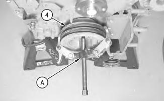
Illustration 2 g00985496
The engine has been removed for photographic purposes.
2. Use Tooling (A) and remove crankshaft pulley (4) from the engine.
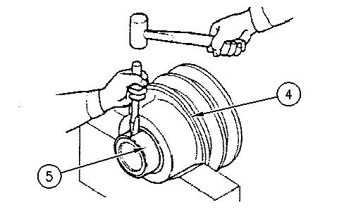
Illustration 3 g00985500
3. If it is necessary to remove wear sleeve (5) from crankshaft pulley (4), use a hammer and a chisel. Hold the chisel at right angles to the surface of the wear sleeve. Tap the wear sleeve in three places. You can remove the wear sleeve once the tension is released.
Installation Procedure
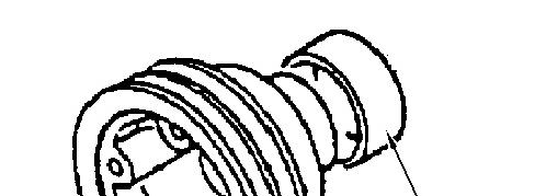
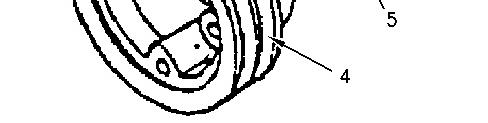
Illustration 4 g00985512
1. Raise the temperature of wear sleeve (5) in order to install wear sleeve (5) onto crankshaft pulley (4) .
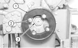
Illustration 5
g00985495
2. Position crankshaft pulley (4) onto the engine. Install nut (3). Position pulley (1) and install bolts (2) .
End By: Install the V-belts. Refer to Disassembly and Assembly, "V-Belts - Remove and Install". Copyright 1993 - 2019 Caterpillar Inc.
Product: EXCAVATOR
Model: 314C EXCAVATOR PCA
Configuration: 314C CR & 314C LCR Excavators PCA00001-UP (MACHINE) POWERED BY 3064 Engine
Disassembly and Assembly 314C ExcavatorEngine Supplement Media Number -RENR6604-03
Cylinder Head - Install
SMCS - 1100-012
Installation Procedure
i01895126
NOTICE
Care must be taken to ensure that fluids are contained during performance of inspection, maintenance, testing, adjusting and repair of the product. Be prepared to collect the fluid with suitable containers before opening any compartment or disassembling any component containing fluids.
Refer to Special Publication, NENG2500, "Caterpillar Tools and Shop Products Guide" for tools and supplies suitable to collect and contain fluids on Caterpillar products.
Dispose of all fluids according to local regulations and mandates.
1. Install the cylinder head. Refer to Disassembly and Assembly, "Cylinder Head - Install" for the proper procedure.
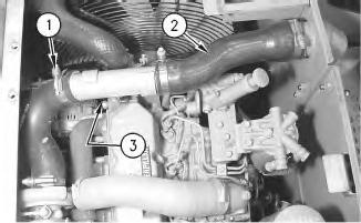
Illustration 1
2. Connect harness assembly (3) (not shown). Install three hoses (2). Install six hose clamps (1) .
3. Fill the cooling system with coolant. Refer to Operation and Maintenance Manual, "Lubricant Viscosities" and Operation and Maintenance Manual, "Capacities (Refill)".
4. Close the hood.
Copyright 1993 - 2019 Caterpillar Inc. All Rights Reserved. Private Network For SIS Licensees. Sat Oct 26 10:08:11 UTC+0530 2019
Product: EXCAVATOR
Model: 314C EXCAVATOR PCA
Configuration: 314C CR & 314C LCR Excavators PCA00001-UP (MACHINE) POWERED BY 3064 Engine
Disassembly and Assembly 314C ExcavatorEngine Supplement
-RENR6604-03
Cylinder Head - Remove
SMCS - 1100-011
Removal Procedure
At operating temperature, the engine coolant is hot and under pressure.
Steam can cause personal injury.
Check the coolant level only after the engine has been stopped and the fill cap is cool enough to touch with your bare hand.
Remove the fill cap slowly to relieve pressure.
Cooling system conditioner contains alkali. Avoid contact with the skin and eyes to prevent personal injury.
NOTICE
Care must be taken to ensure that fluids are contained during performance of inspection, maintenance, testing, adjusting and repair of the product. Be prepared to collect the fluid with suitable containers before opening any compartment or disassembling any component containing fluids.
i01895096
Refer to Special Publication, NENG2500, "Caterpillar Tools and Shop Products Guide" for tools and supplies suitable to collect and contain fluids on Caterpillar products.
Dispose of all fluids according to local regulations and mandates.
1. Raise the hood.
2. Drain the engine coolant. Refer to Operation and Maintenance Manual, "Cooling System Coolant (ELC) - Change".
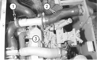
3. Remove six hose clamps (1). Remove three hoses (2). Disconnect harness assembly (3) (not shown).
4. Remove the cylinder head. Refer to Disassembly and Assembly, "Cylinder Head - Remove" for the proper procedure. Copyright 1993 - 2019 Caterpillar Inc. All Rights Reserved.
Network For SIS Licensees. Sat Oct 26 10:07:54 UTC+0530 2019
This is the sample of the manual click on the download link for complete manual
DOWNLOAD LINK
For some reason if link does not work download this pdf and then click