Installation Procedure
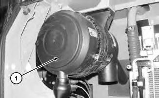
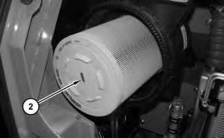
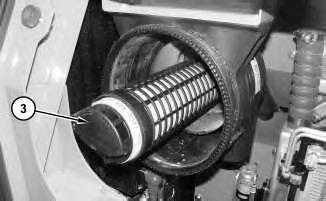
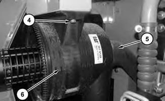
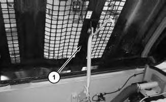
1. Install air cleaner in reverse order of removal.
Copyright 1993 - 2024 Caterpillar Inc. All Rights Reserved. Private Network For SIS Licensees. Wed Feb 14 23:55:40 UTC+0530 2024
Product: EXCAVATOR
Model: 312E EXCAVATOR PZL
Configuration: 312E & 312E L Excavators PZL00001-UP (MACHINE) POWERED BY C4.4 Engine
Disassembly and Assembly
312E Excavator C4.4 Engine Supplement
Media Number -KENR9849-00 Publication Date -01/12/2011 Date Updated -06/12/2011
Alternator - Remove and Install
SMCS - 1405-010
Removal Procedure
1. Turn the battery disconnect switch to the OFF position.
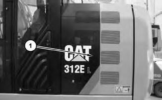
2. Open engine hood (1) .
i04598553
Illustration 1
g02751140
2
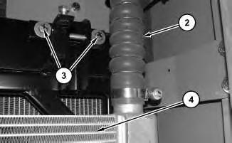
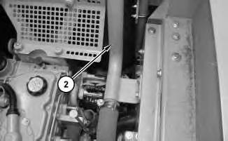
3. Disconnect tube (2) from the turbocharger. Position hose (2) out of the way.
Illustration 3
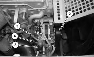
4. Remove the belt (2) for the alternator. Refer to Operation and Maintenance Manual, "BeltsInspect/Adjust/Replace".Disconnect cable assembly (3), (4) and (5) .
4
Illustration
g02751296
g02751317
Illustration
g02751378
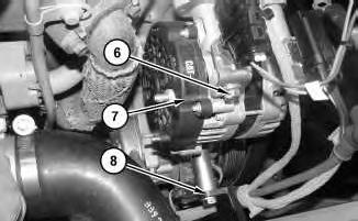
5. Remove clamp (8). Remove bolts (6). Repeat for the bottom bolts. Remove alternator (7) .
Installation Procedure
1. Install alternator (7) in reverse order of removal.
Copyright 1993 - 2024 Caterpillar Inc. All Rights Reserved. Private Network For SIS Licensees.
Wed Feb 14 23:50:46 UTC+0530 2024
Product: EXCAVATOR
Model: 312E EXCAVATOR PZL
Configuration: 312E & 312E L Excavators PZL00001-UP (MACHINE) POWERED BY C4.4 Engine
Disassembly and Assembly
312E Excavator C4.4 Engine Supplement
Media Number -KENR9849-00
Publication Date -01/12/2011
Battery - Remove and Install
SMCS - 1401-010
Removal Procedure
Illustration 1
Date Updated -06/12/2011
i04629710
g02772261
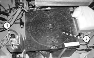
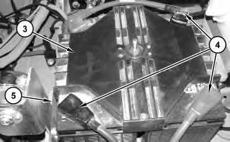
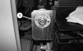
1. Turn the battery disconnect switch (1) to the OFF position. Remove cover (2) .
2. Remove cover (3). Disconnect cable assemblies (4). Remove battery (5) .
Installation Procedure
1. Install battery (5) in reverse order of the removal.
Copyright 1993 - 2024 Caterpillar Inc. All Rights Reserved. Private Network For SIS Licensees.
Wed Feb 14 23:50:33 UTC+0530 2024
Product: EXCAVATOR
Model: 312E EXCAVATOR PZL
Configuration: 312E & 312E L Excavators PZL00001-UP (MACHINE) POWERED BY C4.4 Engine
Disassembly and Assembly
312E Excavator C4.4 Engine Supplement
Media Number -KENR9849-00 Publication Date -01/12/2011 Date Updated -06/12/2011
Belt Tightener - Remove and Install
SMCS - 1358-010
Removal Procedure
1. Open hood to the engine compartment.
Illustration 1 g02788585
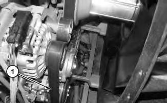
2. Remove belt (1). Refer to Operation and Maintenance Manual, " BeltInspect/Adjust/Replace".
i04644398
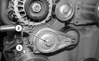
3. Remove bolt (2) and belt tensioner (3) .
Installation Procedure
1. Install belt tensioner (3) in reverse order of the removal.
a. Tighten bolt (2) to a torque of 45 N·m (33 lb ft).
Copyright 1993 - 2024 Caterpillar Inc. All Rights Reserved. Private Network For SIS Licensees. Wed Feb 14 23:57:55 UTC+0530 2024
Product: EXCAVATOR
Model: 312E EXCAVATOR PZL
Configuration: 312E & 312E L Excavators PZL00001-UP (MACHINE) POWERED BY C4.4 Engine
Disassembly and Assembly
312E Excavator C4.4 Engine Supplement Media
Clean Emissions Module - Remove and Install
SMCS - 1050-010; 7279-010
Removal Procedure
Wear goggles, gloves, protective clothing, and a National Institute for Occupational Safety and Health (NIOSH) approved P95 or N95 halfface respirator when handling a used Diesel Particulate Filter or Catalytic Converter Muffler. Failure to do so could result in personal injury.
The muffler, catalytic converter/muffler, and diesel particulate filter will become extremely hot during engine operation. A hot muffler, catalytic converter/muffler and diesel particulate filter can cause serious burns. Allow adequate cooling time before working on or near the muffler, catalytic converter/muffler and diesel particulate filter.
NOTICE
Do not strike any part of th assembly of the Diesel Particulate Filter (DPF). Do not allow any object to contact the internal element of the
DPF. If the internal element of the DPF becomes damaged, the assembly must be replaced
1. Turn the battery disconnect switch (1) to the OFF position
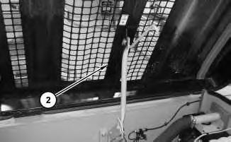
2. Remove hood (2) .
Illustration 1
g02775905
Illustration 2
g02774896
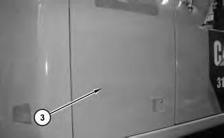
Illustration 3
3. Open access door (3) .
g02774956
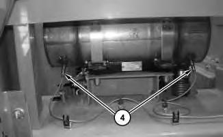
Illustration 4
4. Remove sensor assemblies (4) .
g02776018
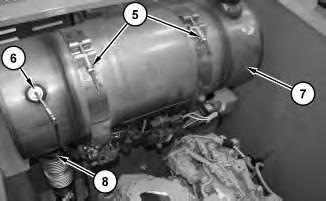
Illustration 5
g02776036
5. Remove sensor assembly (6). Loosen clamp (8). Loosen straps (5) and clean emissions module filter (7) .
Installation Procedure
1. Install Clean Emissions Module (7) in the reverse order of the removal.
a. Tighten straps (5) to a torque of 17 N·m (13 lb in).
b. Tighten clamp (8) to a torque of 35 N·m (26 lb ft).
1993 - 2024 Caterpillar Inc.
Product: EXCAVATOR
Model: 312E EXCAVATOR PZL
Configuration: 312E & 312E L Excavators PZL00001-UP (MACHINE)
Disassembly and Assembly
312E Excavator C4.4 Engine Supplement
Cooling System Package (Radiator, Hydraulic Oil Cooler)
Remove and Install
SMCS - 1353-010; 1353; 1374-010
Removal Procedure
Table 1
Required Tools Tool
A 138-7575 Link Bracket 2
Personal injury can result from hydraulic oil pressure and hot oil.
Hydraulic oil pressure can remain in the hydraulic system after the engine has been stopped. Serious injury can be caused if this pressure is not released before any service is done on the hydraulic system.
Make sure all of the work tools have been lowered to the ground, and the oil is cool before removing any components or lines. Remove the oil filler cap only when the engine is stopped, and the filler cap is cool enough to touch with your bare hand.
-
i04600509
Personal injury can result from hot coolant, steam and alkali.
At operating temperature, engine coolant is hot and under pressure. The radiator and all lines to heaters or the engine contain hot coolant or steam. Any contact can cause severe burns.
Remove cooling system pressure cap slowly to relieve pressure only when engine is stopped and cooling system pressure cap is cool enough to touch with your bare hand.
Do not attempt to tighten hose connections when the coolant is hot, the hose can come off causing burns.
Cooling System Coolant Additive contains alkali. Avoid contact with skin and eyes.
1. Refer to Operation and Maintenance Manual, "Hydraulic System Oil - Change" for the correct draining and filling procedures.
2. Refer to Operation and Maintenance Manual, "Cooling System Coolant (ELC) - Change" for the correct draining and filling procedures.
3. Open the hood and left access door.
4. Turn the battery disconnect switch (1) to the OFF position.
Illustration 1
g02753279
2
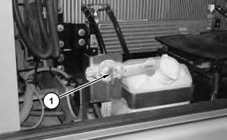
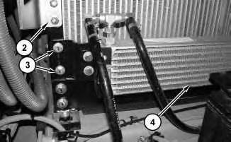
5. Remove bracket (2). Remove bolts (3), repeat for opposite side and place fuel cooler (4) to the side.
Illustration 3
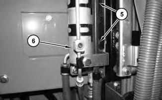
6. Remove bolts (5) and place receiver assembly (6) to the side.
4
Illustration
g02753296
g02753338
Illustration
g02753416
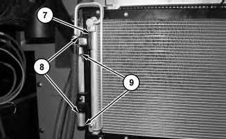
7. Remove retaining rings (9) and pins (8) and place refrigerant condenser (7) to the side.
5
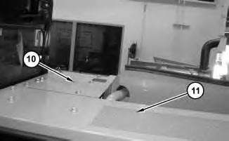
8. Remove panels (10) and (11) .
6
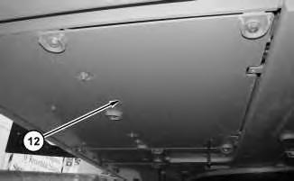
9. Remove guard (12) .
Illustration
g02753420
Illustration
g02753518
Illustration 7
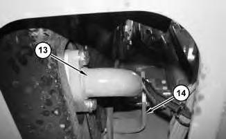
10. Remove tube (13) and bracket (14) .
Illustration 8
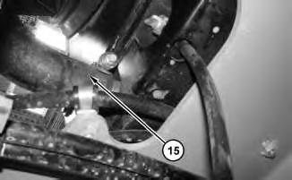
11. Remove hose (15) .
g02753533
Illustration 9
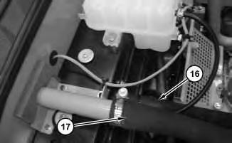
12. Remove hoses (16) and (17) .
g02753539
g02753530
10
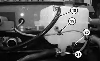
13. Remove hoses (18) and (21). Remove cable straps (19) and disconnect harness assembly (20) .
11
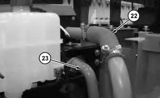
14. Disconnect tube assemblies (23) and hose (22) .
12
Illustration
g02753541
Illustration
g02753547
Illustration
g02753549
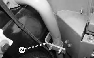
15. Remove bracket (24) .
13
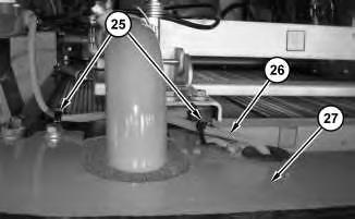
16. Remove cable straps (25). Pull harness assembly (26) through panel (27) .
Illustration 14
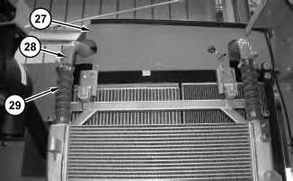
17. Remove panel (27). Disconnect hose (29). Repeat for opposite side. Remove tube assembly (28). Repeat for opposite side.
Illustration
g02753556
g02753558
15
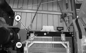
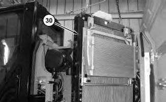
18. Attach Tooling (A) and suitable lifting device to cooling system package (30). The weight of cooling system package (30) is approximately 150 kg (330 lb).
Illustration 16
g02753638
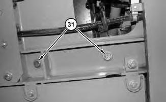
19. Remove bolts (31). Repeat for opposite side.
17
Illustration
g02753616
Illustration
g02753661
20. Remove cooling package (30) .