Product: EXCAVATOR
Model: 312D EXCAVATOR RHL
Configuration: 312D & 312D L Excavators RHL00001-UP (MACHINE) POWERED BY C4.2 Engine
Operation and Maintenance Manual
312D and 313D Excavators
Media Number -SEBU8038-12
Foreword
Literature Information
Date -01/04/2014 Date Updated -19/06/2017
This manual should be stored in the operator's compartment in the literature holder or seat back literature storage area.
This manual contains safety information, operation instructions, transportation information, lubrication information and maintenance information.
Some photographs or illustrations in this publication show details or attachments that can be different from your machine. Guards and covers might have been removed for illustrative purposes.
Continuing improvement and advancement of product design might have caused changes to your machine which are not included in this publication. Read, study and keep this manual with the machine.
Whenever a question arises regarding your machine, or this publication, please consult your Cat dealer for the latest available information.
Safety
The safety section lists basic safety precautions. In addition, this section identifies the text and locations of warning signs and labels used on the machine.
Read and understand the basic precautions listed in the safety section before operating or performing lubrication, maintenance and repair on this machine.
Operation
The operation section is a reference for the new operator and a refresher for the experienced operator. This section includes a discussion of gauges, switches, machine controls, attachment controls, transportation and towing information.
s00037320
Photographs and illustrations guide the operator through correct procedures of checking, starting, operating and stopping the machine.
Operating techniques outlined in this publication are basic. Skill and techniques develop as the operator gains knowledge of the machine and its capabilities.
Maintenance
The maintenance section is a guide to equipment care. The Maintenance Interval Schedule (MIS) lists the items to be maintained at a specific service interval. Items without specific intervals are listed under the "When Required" service interval. The Maintenance Interval Schedule lists the page number for the step-by-step instructions required to accomplish the scheduled maintenance. Use the Maintenance Interval Schedule as an index or "one safe source" for all maintenance procedures.
Maintenance Intervals
Use the service hour meter to determine servicing intervals. Calendar intervals shown (daily, weekly, monthly, etc.) can be used instead of service hour meter intervals if they provide more convenient servicing schedules and approximate the indicated service hour meter reading. Recommended service should always be performed at the interval that occurs first.
Under extremely severe, dusty or wet operating conditions, more frequent lubrication than is specified in the maintenance intervals chart might be necessary.
Perform service on items at multiples of the original requirement. For example, at every 500 service hours or 3 months, also service those items listed under every 250 service hours or monthly and every 10 service hours or daily.
California Proposition 65 Warning
Diesel engine exhaust and some of its constituents are known to the State of California to cause cancer, birth defects, and other reproductive harm.
Battery posts, terminals and related accessories contain lead and lead compounds. Wash hands after handling.
Certified Engine Maintenance
Proper maintenance and repair is essential to keep the engine and machine systems operating correctly. As the heavy duty off-road diesel engine owner, you are responsible for the performance of the required maintenance listed in the Owner Manual, Operation and Maintenance Manual, and Service Manual.
It is prohibited for any person engaged in the business of repairing, servicing, selling, leasing, or trading engines or machines to remove, alter, or render inoperative any emission related device or element of design installed on or in an engine or machine that is in compliance with the regulations (40 CFR Part 89). Certain elements of the machine and engine such as the exhaust system, fuel system, electrical system, intake air system and cooling system may be emission related and should not be altered unless approved by Caterpillar.
Machine Capacity
Additional attachments or modifications may exceed machine design capacity which can adversely affect performance characteristics. Included would be stability and system certifications such as brakes, steering, and rollover protective structures (ROPS). Contact your Cat dealer for further information.
Cat Product Identification Number
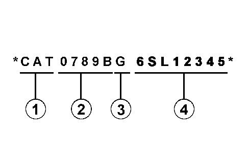
Effective First Quarter 2001 the Cat Product Identification Number (PIN) has changed from 8 to 17 characters. In an effort to provide uniform equipment identification, Caterpillar and other construction equipment manufacturers are moving to comply with the latest version of the product identification numbering standard. Non-road machine PINs are defined by ISO 10261. The new PIN format will apply to all Cat machines and generator sets. The PIN plates and frame marking will display the 17 character PIN. The new format will look like the following:
Illustration 1 g00751314
Where:
1. Caterpillar's World Manufacturing Code (characters 1-3)
2. Machine Descriptor (characters 4-8)
3. Check Character (character 9)
4. Machine Indicator Section (MIS) or Product Sequence Number (characters 10-17). These were previously referred to as the Serial Number.
Machines and generator sets produced before First Quarter 2001 will maintain their 8 character PIN format.
Components such as engines, transmissions, axles, etc. and work tools will continue to use an 8 character Serial Number (S/N).
Copyright 1993 - 2023 Caterpillar Inc. All Rights Reserved.
Private Network For SIS Licensees.
Sun Nov 5 14:16:17 UTC+0530 2023
This is the sample of the manual click on the download link for complete manual
DOWNLOAD LINK
For some reason if link does not work download this pdf and then click
Product: EXCAVATOR
Model: 312D EXCAVATOR RHL
Configuration: 312D & 312D L Excavators RHL00001-UP (MACHINE) POWERED BY C4.2 Engine
Operation and Maintenance Manual
312D and 313D Excavators
Media Number -SEBU8038-12 Publication Date -01/04/2014 Date Updated -19/06/2017
Fuses - Replace
SMCS - 1417-510
Illustration 1
i03479740
g01101038
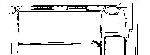
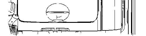
The fuse panel is located on the left side of the interior storage box. Remove the cover in order to access the fuses.
Fuses - Fuses protect the electrical system from damage that is caused by overloaded circuits. Change a fuse if the element separates. If the element of a new fuse separates, check the circuit and/or repair the circuit.
NOTICE
Always replace fuses with the same type and capacity fuse that was removed. Otherwise, electrical damage could result.
NOTICE
If it is necessary to replace fuses frequently, an electrical problem may exist.
Contact your Caterpillar dealer.
To replace a fuse, use the puller that is stored in the fuse panel. One fuse of 5 Amperes, three fuses of 10 Amperes, two fuses of 15 Amperes, two fuses of 20 Amperes, two fuses of 25 Amperes, and one fuse of 30 Amperes are contained in the fuse panel as spare fuses.
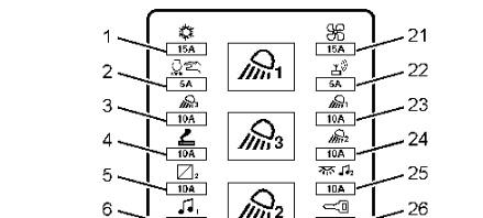
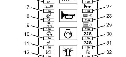
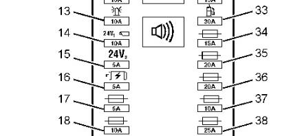
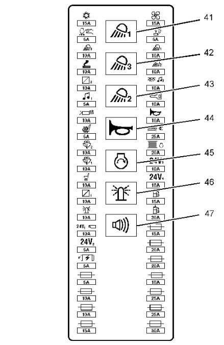
The following list identifies the circuits that are protected by each fuse. The amperage for each fuse is included with each circuit.
2
Illustration
g01818554
(1) Air Conditioner - 15 Amp
(2) Automatic Engine Speed Control (AEC) - 5 Amp
(3) Chassis Light - 10 Amp
(4) Cigar Lighter - 10 Amp
(5) 12 Volt 7 Amp Converter - 10 Amp
(6) Switch Panel And Radio - 5 Amp
(7) Attachment Solenoid - 10 Amp
(8) Seat Heater - 5 Amp
(9) Lower Window Wiper and Lower Window Washer - 10 Amp
(10) Window Wiper And Window Washer - 10 Amp
(11) Air Suspension Seat - 10 Amp
(12) 12 Volt 7 Amp Converter - 10 Amp
(13) Beacon - 10 Amp
(14) Inspection Lamp 1 and Camera - 10 Amp
(15) Inspection Lamp 2 - 5 Amp
(16) Alternator Regulator - 5 Amp
(17) Spare - 5 Amp
(18) Spare - 10 Amp
(19) Spare - 10 Amp
(20) Spare - 15 Amp
(21) Heater and Air Conditioner Blower Fan - 15 Amp
(22) Product Link - 5 Amp
(23) Boom Light - 10 Amp
(24) Cab Light - 10 Amp
(25) Cab Dome Light and Radio Memory - 10 Amp
(26) Engine Start Switch - 10 Amp
(27) Horn - 10 Amp
(28) Machine Control Module - 25 Amp
(29) Engine Control Module (ECM) - 20 Amp
(30) Inspection Lamp 3 - 10 Amp
(31) Inspection Lamp 4 - 10 Amp
(32) Refueling Pump - 15 Amp
(33) Refueling Pump - 30 Amp
(34) Spare - 15 Amp
(35) Spare - 20 Amp
(36) Spare - 20 Amp
(37) Spare - 10 Amp
(38) Spare - 25 Amp
(39) Spare - 25 Amp
(40) Spare - 30 Amp
Relays
3
(41) Boom Light - Relay
(42) Chassis Lamp - Relay
(43) Cab Lamp - Relay
(44) Horn - Relay
(45) Neutral Start - Relay
(46) Beacon - Relay
(47) Travel Alarm - Relay
Product: EXCAVATOR
Model: 312D EXCAVATOR RHL
Configuration: 312D & 312D L Excavators RHL00001-UP (MACHINE) POWERED BY C4.2 Engine
Operation and Maintenance Manual
312D and 313D Excavators
Media Number -SEBU8038-12
Fuel Tank Water and Sediment - Drain
SMCS - 1273-543
Updated -19/06/2017
i04363385
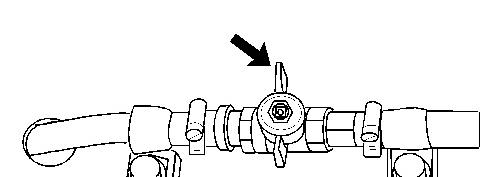
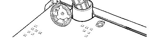
Refer to this Operation and Maintenance Manual, "Fuel Tank Shutoff and Drain Control" for the exact location of the fuel tank drain valve
Note: Refer to Operation and Maintenance Manual, "General Hazard Information" for information on containing fluid spillage.
Illustration 1 g01043694
Typical example
1. Open the drain valve by turning the valve counterclockwise. Allow the water and the sediment to drain into a suitable container.
Note: Dispose of drained fluids according to local regulations.
2. Close the drain valve by turning the valve clockwise. Copyright 1993 - 2023 Caterpillar Inc.
Rights Reserved.
Network For SIS Licensees.
Sun Nov 5 14:41:33 UTC+0530 2023
Product: EXCAVATOR
Model: 312D EXCAVATOR RHL
Configuration: 312D & 312D L Excavators RHL00001-UP (MACHINE) POWERED BY C4.2 Engine
Operation and Maintenance Manual
312D and 313D Excavators
Media Number -SEBU8038-12 Publication Date -01/04/2014 Date Updated -19/06/2017
Fuel Tank Cap and Strainer - Clean
SMCS - 1273-070-STR
Illustration 1
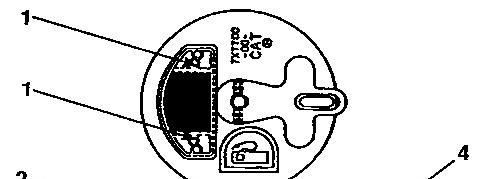
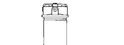
1. Remove the fuel cap.
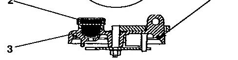
2. Inspect seal (4) for damage. Replace the seal, if necessary.
g00824193
3. Remove screws (1), filter assembly (2), drain valve (3) and the gaskets.
i01589598
Illustration 2 g00824196
Note: Refer to Operation and Maintenance Manual, "General Hazard Information" for information on Containing Fluid Spillage.
4. Remove the strainer that is located in the filler opening.
5. Wash the strainer and the fuel tank cap in a clean, nonflammable solvent.
6. Install a new cap filter kit. Install the gaskets, drain valve (3), filter assembly (2), and screws (1).
7. Install the strainer into the filler opening.
8. Install the fuel tank cap.
Product: EXCAVATOR
Model: 312D EXCAVATOR RHL
Configuration: 312D & 312D L Excavators RHL00001-UP (MACHINE) POWERED BY C4.2 Engine
Operation and Maintenance Manual
312D and 313D Excavators
Media Number -SEBU8038-12
Date -01/04/2014 Date Updated -19/06/2017
Fuel System Water Separator - Drain
SMCS - 1263
1. Open the access door on the left side of the machine.
2. Provide a suitable container for used fluid.
Note: Refer to Operation and Maintenance Manual, "General Hazard Information" for information on Containing Fluid Spillage.
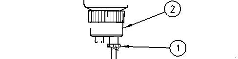
Illustration 1 g00751973 (1) Drain valve (2) Bowl
3. Check bowl (2) in the bottom of the water separator. Open drain valve (1). Drain the water and sediment in the bowl.
i02468252
Note: Dispose of used fluids according to local regulations.
4. Close drain valve (1).
5. Close the access door.
Copyright 1993 - 2023 Caterpillar Inc. All Rights Reserved. Private Network For SIS Licensees.
Sun Nov 5 14:41:09 UTC+0530 2023
Product: EXCAVATOR
Model: 312D EXCAVATOR RHL
Configuration: 312D & 312D L Excavators RHL00001-UP (MACHINE) POWERED BY C4.2 Engine
Operation and Maintenance Manual
312D and 313D Excavators
Media Number -SEBU8038-12
Date -01/04/2014 Date Updated -19/06/2017
Fuel System Third Filter - Replace
SMCS - 1261-510
Personal injury or death may result from failure to adhere to the following procedures.
Fuel leaked or spilled onto hot surfaces or electrical components can cause a fire.
Clean up all leaked or spilled fuel. Do not smoke while working on the fuel system.
Turn the disconnect switch OFF or disconnect the battery when changing fuel filters.
NOTICE
Do not fill the fuel filters with fuel before installing the fuel filters. The fuel will not be filtered and could be contaminated. Contaminated fuel will cause accelerated wear to fuel system parts.
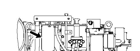
1. Open the engine hood.
Note: Refer to Operation and Maintenance Manual, "General Hazard Information" for information on containing fluid spillage.
i03007650
Illustration 1 g01361061
2. Remove the filter.
Note: Always discard used filters according to local regulations.
3. Clean the filter mounting base. Make sure that all of the used seal is removed.
4. Coat the seal of the new filter with clean diesel fuel.
5. Install the new fuel filter by hand.
Instructions for the installation of the filter are printed on the side of each Caterpillar spinon filter. For non-Caterpillar filters, refer to the installation instructions that are provided by the supplier of the filter.
6. Prime the fuel system. See Operation and Maintenance Manual, "Fuel System - Prime" for instructions.
7. Close the engine hood. Copyright 1993 - 2023 Caterpillar Inc.
Network For SIS Licensees. Sun Nov 5 14:40:56 UTC+0530 2023
Product: EXCAVATOR
Model: 312D EXCAVATOR RHL
Configuration: 312D & 312D L Excavators RHL00001-UP (MACHINE) POWERED BY C4.2 Engine
Operation and Maintenance Manual 312D and 313D Excavators
Media Number -SEBU8038-12
-01/04/2014
Fuel System Secondary Filter - Replace
SMCS - 1261-510
Note: The replacement interval for this filter is recommended at every 250 service hours or monthly for machines that meet the following conditions for severe applications:
• Poor fuel storage or poor refueling procedures
• Poor fuel cleanliness or low fuel quality
• Dusty conditions
Machines that are operated in normal applications should follow the replacement interval of every 500 service hours or 3 months.
Personal injury or death may result from failure to adhere to the following procedures.
Fuel leaked or spilled onto hot surfaces or electrical components can cause a fire.
Clean up all leaked or spilled fuel. Do not smoke while working on the fuel system.
Turn the disconnect switch OFF or disconnect the battery when changing fuel filters.
i03007496
Do not fill the fuel filters with fuel before installing the fuel filters. The fuel will not be filtered and could be contaminated. Contaminated fuel will cause accelerated wear to fuel system parts.
1. Open the engine hood.
Note: Refer to Operation and Maintenance Manual, "General Hazard Information" for information on containing fluid spillage.
1
2. Remove the filter.
Note: Always discard used filters according to local regulations.
3. Clean the filter mounting base. Make sure that all of the used seal is removed.
4. Coat the seal of the new filter with clean diesel fuel.
5. Install the new fuel filter by hand.
Instructions for the installation of the filter are printed on the side of each Caterpillar spinon filter. For non-Caterpillar filters, refer to the installation instructions that are provided by the supplier of the filter.
Illustration
g01359809
6. Prime the fuel system. See Operation and Maintenance Manual, "Fuel System - Prime" for instructions.
7. Close the engine hood.
Copyright 1993 - 2023 Caterpillar Inc. All Rights Reserved. Private Network For SIS Licensees.
Sun Nov 5 14:40:44 UTC+0530 2023
Product: EXCAVATOR
Model: 312D EXCAVATOR RHL
Configuration: 312D & 312D L Excavators RHL00001-UP (MACHINE) POWERED BY C4.2 Engine
Operation and Maintenance Manual
312D and 313D Excavators
Media Number -SEBU8038-12
Date -01/04/2014 Date Updated -19/06/2017
Fuel System Primary Filter (Water Separator) ElementReplace
SMCS - 1263-510-FQ
Note: The replacement interval for this filter is recommended at every 250 service hours or monthly for machines that meet the following conditions for severe applications:
• Poor fuel storage or poor refueling procedures
• Poor fuel cleanliness or low fuel quality
• Dusty conditions
Machines that are operated in normal applications should follow the replacement interval of every 500 service hours or 3 months.
Personal injury or death may result from failure to adhere to the following procedures.
Fuel leaked or spilled onto hot surfaces or electrical components can cause a fire.
Clean up all leaked or spilled fuel. Do not smoke while working on the fuel system.
Turn the disconnect switch OFF or disconnect the battery when changing fuel filters.
i03256754
NOTICE
Do not fill the fuel filters with fuel before installing the fuel filters. The fuel will not be filtered and could be contaminated. Contaminated fuel will cause accelerated wear to fuel system parts.
1. Open the access door on the left side of the machine.
Illustration 1 g00752052
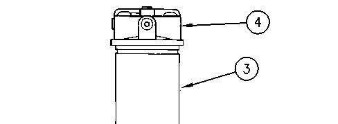
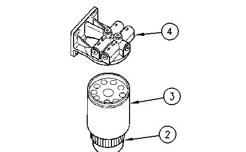
(1) Drain valve (2) Bowl (3) Filter (4) Filter base
2. Turn drain valve (1) counterclockwise in order to open. The drain valve is located on the bottom of the water separator.
Note: Refer to Operation and Maintenance Manual, "General Hazard Information" for information that pertains to containing fluid spillage.
3. Drain the water and the sediment into a suitable container.
Note: Dispose of used fluids according to local regulations.
4. Close the drain valve (1).
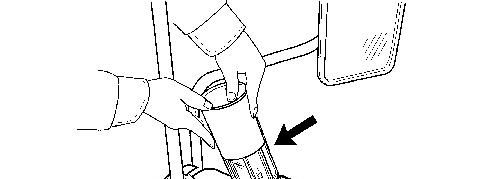
5. Remove filter (3) from filter base (4). A filter wrench may be used to loosen the filter.
6. Remove filter (3) from bowl (2). Discard the used filter.
Note: The water separator bowl is reusable. Do not discard the water separator bowl.
7. Clean the inside surfaces of filter base (4) and bowl (2).
2 g00752055
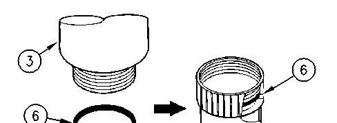
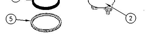
(2) Bowl (3) Filter (5) Cap (6) Seal
8. Remove cap (5) from the bottom of new filter (3). Remove seal (6) from cap (5) and inspect the seal for damage. Replace the seal if the seal is damaged.
9. Lubricate the seal (6) for the bowl (2) with clean diesel fuel or lubricate the seal with motor oil. Place the seal in the groove in the bowl.
3 g00752056
Illustration
Illustration
This is the sample of the manual click on the download link for complete manual
DOWNLOAD LINK
For some reason if link does not work download this pdf and then click