

Note: Use Bookmarks panel to navigate

Product: EXCAVATOR
Model: 312D2 L EXCAVATOR WHJ
Configuration: 312D2 & 312D2 L Excavators
Disassembly and Assembly
3054C Engines for Caterpillar Built Machines
Accessory Drive - Remove and Install
SMCS - 1207-010
Removal Procedure Table 1
i02295086
Keep all parts clean from
This is the sample of the manual click on the download link for complete manual
For some reason if link does not work download this pdf and then click
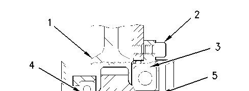
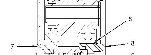
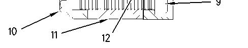
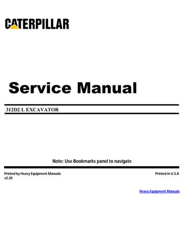
Illustration 1 g00948832
1. Remove the front cover (7). Refer to this Disassembly and Assembly Manual, "Front Cover - Remove and Install".
2. Remove the Allen head screws (2) and (9). Remove the accessory drive assembly (8) from the rear face of the front housing (11).
3. Remove circlip (6) from housing (8).
4. Use the Tooling (A) in order to remove the bearings (3) and (4) from the gear and the housing.
5. Remove the O-ring (12) from the front housing (8) and discard the O-ring.
Installation
Procedure
2
Keep all parts clean from contaminants.
Contaminants may cause rapid wear and shortened component life.
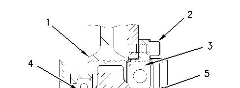

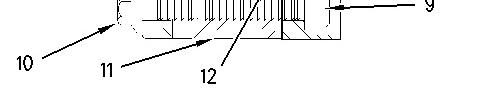
Illustration 2 g00948832
1. Inspect the condition of the teeth and the splines of the gear (5), the bearings (3 and 4), the circlip (6), and the groove for the circlip in the front housing (8) for wear and for damage. Replace any worn component or any damaged component.
2. Apply a small continuous bead of the Tooling (B) to the outer surface of the bearing (4). Support the front face of the housing (8). Position the bearing in the housing. Use a suitable adapter on the outer race of the bearing and press the bearing into the housing (8) until the bearing is against the front face of the recess. Remove any excess bearing mount compound.
3. Apply a small continuous bead of the Tooling (B) to the inner surface of the bearing (4). Support the bearing (4). Position the small hub of the gear (5) toward the bearing and press the gear (5) into the bearing until the shoulder of the gear is against the bearing. Remove any excess bearing mount compound.
4. Apply a small continuous bead of the Tooling (B) to the inner surface and the outer surface of the bearing (3). Support the bearing (4). Use a suitable adapter on the outer race of the bearing (3) and press the bearing into the housing and onto the shoulder of the gear. Remove any excess bearing mount compound.
5. Install the circlip (6) into the groove in the front housing (8). Install a new O-ring seal (12) on housing (8).
6. Lubricate the O-ring seal with red rubber grease and install the housing in front housing (11). Install Allen head screws (2) and (9) to secure housing (8) in the front housing.
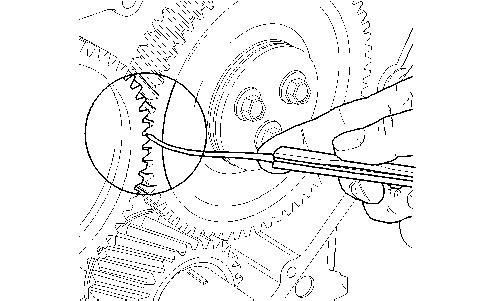
Illustration 3 g00946787
Typical Example
7. Check the backlash between the idler gear and gear (5). The backlash for the gears is 0.11 to 0.17 mm (0.004 to 0.007 inch).
8. Install the front cover (7) on the front housing. Refer to this Disassembly and Assembly Manual, "Front Cover - Remove and Install".
Copyright 1993 - 2025 Caterpillar Inc. All Rights Reserved. Private Network For SIS Licensees. Mon Mar 31 23:46:50 UTC+0700 2025
Product: EXCAVATOR
Model: 312D2 L EXCAVATOR WHJ
Configuration: 312D2 & 312D2 L Excavators WHJ00001-UP (MACHINE) POWERED BY 3054C Engine
Disassembly and Assembly
3054C Engines for Caterpillar Built Machines
Media Number -SENR5069-19 Publication Date -01/05/2015 Date Updated -30/07/2020
Alternator - Install
SMCS - 1405-012
Installation Procedure
Note: If the alternator pulley was removed, install the alternator pulley and the nut (3). Tighten the nut to a torque of 80 ± 10 N·m (59 ± 7 lb ft).
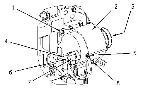
Illustration 1 g00999883
Typical Example
1. Put the alternator (2) in position on the engine.
2. Install the nut and the setscrew (1). Tighten the nut finger tight.
3. Install the clamp screw (8) through the adjustment bracket and into the alternator. Do not tighten the clamp screw (8) at this time.
4. Install the V-belts on the alternator pulley. Adjust the tension on the V-belts by moving the alternator (2) away from the engine. Tighten the clamp screw (8) after the correct tension is made. Refer to Testing and Adjusting, "V-Belt - Test" for the correct tension of the V-belts.
Note: If the V-belt cannot be checked with a gauge, press on the V-belt at the center of the longest free length in order to check the deflection. Under a moderate amount of pressure, the V-belt should have a deflection of 10 mm (0.40 inch).
5. Tighten the nut and the setscrew (1).
6. Connect the harness assemblies (4), (6), and (7) to the alternator.
7. Connect the ground harness assembly (5) to the alternator.
8. Turn the battery disconnect switch to the ON position.
Product: EXCAVATOR
Model: 312D2 L EXCAVATOR WHJ
Configuration: 312D2 & 312D2 L Excavators WHJ00001-UP (MACHINE) POWERED BY 3054C Engine
Disassembly and Assembly
3054C Engines for Caterpillar Built Machines
Media Number -SENR5069-19 Publication Date -01/05/2015 Date Updated -30/07/2020
i02308906
Alternator - Remove
SMCS - 1405-011
Removal Procedure
1. Turn the battery disconnect switch to the OFF position.
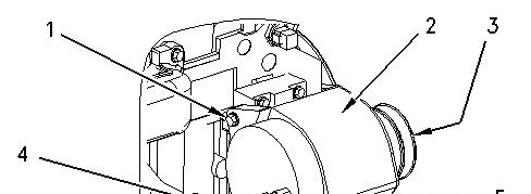
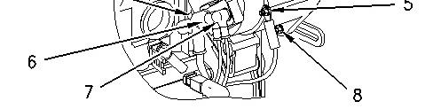
Illustration 1 g00999883
Typical Example
2. Place an index mark on all of the harness assemblies that are connected to the alternator.
3. Disconnect the harness assemblies (4), (6), and (7) from the alternator.
4. Disconnect the ground harness assembly (5) from the alternator.
5. Loosen the nut and the setscrew (1).
6. Remove the clamp screw (8) and slide the alternator (2) toward the engine. Remove the Vbelts from the alternator pulley.
7. Remove the setscrew (1) from the alternator bracket. Remove the alternator (2) from the engine.
8. If necessary, remove the nut (3) and the alternator pulley from the alternator. Copyright 1993 - 2025 Caterpillar Inc. All Rights Reserved.
Network For SIS Licensees. Tue Apr 1 00:05:10 UTC+0700 2025
Product: EXCAVATOR
Model: 312D2 L EXCAVATOR WHJ
Configuration: 312D2 & 312D2 L Excavators WHJ00001-UP (MACHINE) POWERED BY 3054C Engine
Disassembly and Assembly
3054C Engines for Caterpillar Built Machines
Bearing Clearance - Check
SMCS - 1203-535; 1219-535
Measurement Procedure Table 1
Required Tools
Plastic Gauge (Green)
to
mm
Plastic Gauge (Red)
Plastic Gauge (Blue)
to 0.229 mm (0.004 to 0.009 inch)
Plastic Gauge (Yellow) 0.230 to 0.510 mm (0.009 to 0.020 inch)
Note: Plastic gauge may not be necessary when the engine is in the chassis.
NOTICE
Keep all parts clean from contaminants.
Contaminants may cause rapid wear and shortened component life.
Note: Cat does not recommend the checking of the actual bearing clearances particularly on small engines. This is because of the possibility of obtaining inaccurate results and the possibility of damaging the bearing or the journal surfaces. Each Cat engine bearing is quality checked for specific wall thickness.
Note: The measurements should be within specifications and the correct bearings should be used. If the crankshaft journals and the bores for the block and the rods were measured during disassembly, no further checks are necessary. However, if the technician still wants to measure the bearing clearances, Tooling (A) is an acceptable method. Tooling (A) is less accurate on journals with small diameters if clearances are less than 0.10 mm (0.004 inch).
NOTICE
Lead wire, shim stock or a dial bore gauge can damage the bearing surfaces.
The technician must be very careful to use Tooling (A) correctly. The following points must be remembered:
• Ensure that the backs of the bearings and the bores are clean and dry.
• Ensure that the bearing locking tabs are properly seated in the tab grooves.
• The crankshaft must be free of oil at the contact points of Tooling (A).
1. Put a piece of Tooling (A) on the crown of the bearing that is in the cap.
Note: Do not allow Tooling (A) to extend over the edge of the bearing.
2. Use the correct torque-turn specifications in order to install the bearing cap. Do not use an impact wrench. Be careful not to dislodge the bearing when the cap is installed.
Note: Do not turn the crankshaft when Tooling (A) is installed.
3. Carefully remove the cap, but do not remove Tooling (A). Measure the width of Tooling (A) while Tooling (A) is in the bearing cap or on the crankshaft journal. Refer to Illustration 1.
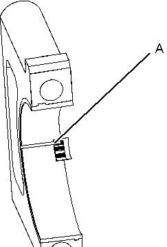

Illustration 1 g01152855
Typical Example
4. Remove all of Tooling (A) before you install the bearing cap.
Note: When Tooling (A) is used, the readings can sometimes be unclear. For example, all parts of Tooling (A) are not the same width. Measure the major width in order to ensure that the parts are within the specification range. Refer to Specifications Manual, "Connecting Rod Bearing Journal" and Specifications Manual, "Main Bearing Journal" for the correct clearances. Copyright 1993 - 2025 Caterpillar Inc.
Product: EXCAVATOR
Model: 312D2 L EXCAVATOR WHJ
Configuration: 312D2 & 312D2 L Excavators WHJ00001-UP (MACHINE) POWERED BY 3054C Engine
Disassembly and Assembly
3054C Engines for Caterpillar Built Machines
Media Number -SENR5069-19
Camshaft - Remove and Install
SMCS - 1210-010
Removal Procedure
Start By:
-30/07/2020
a. Remove the rocker shaft assembly and the pushrods. Refer to Disassembly and Assembly, "Rocker Shaft and Pushrod - Remove".
b. Remove the front housing. Refer to Disassembly and Assembly, "Housing (Front)Remove".
NOTICE
Keep all parts clean from contaminants.
Contaminants may cause rapid wear and shortened component life.
1. Turn the engine upside-down so the valve lifters are held in a position away from the camshaft.
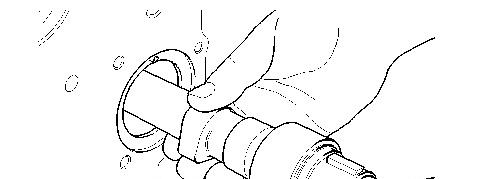
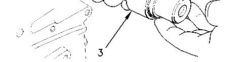
Illustration 1 g00951934
NOTICE
Do not damage the lobes or the bearings when the camshaft is removed or installed.
2. Carefully remove camshaft (3) from the cylinder block.
Installation Procedure
NOTICE
Keep all parts clean from contaminants.
Contaminants may cause rapid wear and shortened component life.
Note: Ensure that the camshaft is clean. Lubricate the camshaft with clean engine oil prior to installation.
NOTICE
Do not damage the lobes or the bearings when the camshaft is removed or installed.
1. Carefully install camshaft (3) in the cylinder block.
End By:
a. Install the front housing. Refer to Disassembly and Assembly, "Housing (Front) - Install".
b. Install the rocker shaft and the pushrods. Refer to Disassembly and Assembly, "Rocker Shaft and Pushrod - Install".
Copyright 1993 - 2025 Caterpillar Inc. All Rights Reserved. Private Network For SIS Licensees. Mon Mar 31 23:49:52 UTC+0700 2025
Product: EXCAVATOR
Model: 312D2 L EXCAVATOR WHJ
Configuration: 312D2 & 312D2 L Excavators WHJ00001-UP (MACHINE) POWERED BY 3054C Engine
Disassembly and Assembly
3054C Engines for Caterpillar Built Machines
Media Number -SENR5069-19 Publication Date -01/05/2015 Date Updated -30/07/2020
Camshaft Bearings - Remove and Install
SMCS - 1211-010
Removal Procedure Table 1
Required Tools
Start By:
a. Remove the camshaft. Refer to Disassembly and Assembly, "Camshaft - Remove and Install".
NOTICE
Keep all parts clean from contaminants.
Contaminants may cause rapid wear and shortened component life.
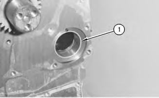
Illustration 1
g00546333

Illustration 2
g00546238
1. Use the Tooling (A) in order to remove the camshaft bearing (1) from the cylinder block.
Installation Procedure
Table 2
Required Tools
Tool Part Number Part Description Qty
A
8S-2241 Camshaft Bearing Tool Group 1
8H-0684 Ratchet Wrench 1
NOTICE
Keep all parts clean from contaminants. Contaminants may cause rapid wear and shortened component life.
Illustration 3
g00546238

Illustration 4
g00546333
1. Use the Tooling (A) in order to install the camshaft bearing (1) into the bore in the cylinder block.
Note: Align the oil hole in camshaft bearing (1) with the oil hole in the bore in the cylinder block.
Note: The camshaft bearing must be inserted until the front edge of the bearing is flush with the face of the recess in the cylinder block.
End By:
a. Install the camshaft. Refer to Disassembly and Assembly, "Camshaft - Remove and Install". Copyright 1993 - 2025 Caterpillar Inc.
Network For SIS Licensees. Mon Mar 31 23:51:54 UTC+0700 2025
Product: EXCAVATOR
Model: 312D2 L EXCAVATOR WHJ
Configuration: 312D2 & 312D2 L Excavators WHJ00001-UP (MACHINE) POWERED BY 3054C Engine
Disassembly and Assembly
3054C Engines for Caterpillar Built Machines
Media Number -SENR5069-19
Publication Date -01/05/2015 Date Updated -30/07/2020
Connecting Rod Bearings - Install
SMCS - 1219-012
Installation Procedure Table 1
Tools
Keep all parts clean from contaminants.
Contaminants may cause rapid wear and shortened component life.
i05830319
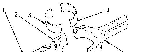
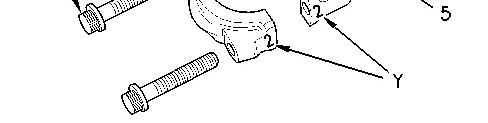
Illustration 1 g00974873
1. Install the upper connecting rod bearing (4) in the connecting rod. The upper connecting rod bearing must be centered in the connecting rod. Lubricate the bearing face with clean engine oil.
2. Pull the connecting rod into position against the crankshaft.
Note: Do not allow the connecting rod to contact the piston cooling jet.
3. Clean the connecting rod cap (2) and the lower connecting rod bearing (3) . Lubricate the bearing face with clean engine oil.
4. Install the lower connecting rod bearing (3) in the connecting rod cap (2) . The lower connecting rod bearing must be centered in the connecting rod cap. Lubricate the bearing face with clean engine oil.
Note: The connecting rod is a forging. The connecting rod has been hydraulically split in order to separate the connecting rod cap and the connecting rod. This process provides accurately matched surfaces. Do Not mix the connecting rod cap and the connecting rod.
Note: Ensure that the etched number on connecting rod bearing cap (2) matches the etched number on the connecting rod (5) . Ensure that the numbers (Y) are on the same side.
5. Install the connecting rod cap (2) .
6. Install new setscrews (1) in the connecting rod.
Note: Do not reuse the old setscrews in order to secure the connecting rod cap.
7. Tighten the setscrews evenly to a torque of 18 N·m (13 lb ft).
8. Tighten the setscrews evenly to a torque of 70 N·m (52 lb ft).
9. Use the Tooling (A) to achieve the correct final torque.
Note: If the Tooling (A) is not used, place an index mark on each setscrew.
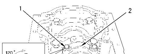
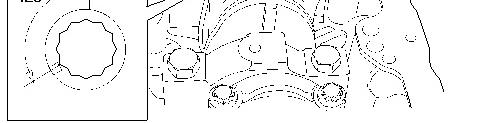
10. Turn the setscrews for an additional 120 degrees.
11. Rotate the crankshaft in order to ensure that there is no binding.
12. Repeat Steps 1 through 11 for the remaining connecting rod bearings.
End By:
a. Install the engine oil pump. Refer to Disassembly and Assembly, "Engine Oil PumpInstall".
b. Install the engine oil pan. Refer to Disassembly and Assembly, "Engine Oil Pan - Remove and Install".
Product: EXCAVATOR
Model: 312D2 L EXCAVATOR WHJ
Configuration: 312D2 & 312D2 L Excavators WHJ00001-UP (MACHINE) POWERED BY 3054C Engine
Disassembly and Assembly
3054C Engines for Caterpillar Built Machines Media
Connecting Rod Bearings - Remove
SMCS - 1219-011
Removal Procedure
Start By:
a. Remove the engine oil pan. Refer to Disassembly and Assembly, "Engine Oil Pan - Remove and Install".
b. Remove the engine oil pump. Refer to Disassembly and Assembly, "Engine Oil PumpRemove".
NOTICE
Keep all parts clean from contaminants.
Contaminants may cause rapid wear and shortened component life.
1. In order to remove the connecting rod caps, rotate the crankshaft in a clockwise direction until the piston is at the bottom center position.
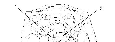
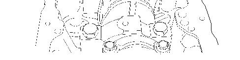
Illustration 1 g00970465
Illustration 2 g00974873
2. Inspect the connecting rod (5) and connecting rod cap (2) for the proper identification mark. The connecting rod and the connecting rod cap should have an etched Number (Y) on the side. The number should match the cylinder number. Mark the connecting rod and the connecting rod cap, if necessary.
3. Remove the setscrews (1) from the connecting rod (5). Remove the connecting rod cap (2). Remove the lower connecting rod bearing (3) from the connecting rod cap.
Note: Do not reuse the setscrews (1). Use new setscrews in order to secure the connecting rod cap for reassembly.
4. Carefully push the connecting rod into the cylinder bore. Remove the upper connecting rod bearing (4) from the connecting rod.
Note: Do not allow the connecting rod to contact the piston cooling jet.
5. Repeat Steps 1 through 4 for the remaining connecting rod bearings.
Copyright 1993 - 2025 Caterpillar Inc. All Rights Reserved. Private Network For SIS Licensees.
Mon Mar 31 23:54:30 UTC+0700 2025
Product: EXCAVATOR
Model: 312D2 L EXCAVATOR WHJ
Configuration: 312D2 & 312D2 L Excavators WHJ00001-UP (MACHINE) POWERED BY 3054C Engine
Disassembly and Assembly
3054C Engines for Caterpillar Built Machines
Media Number -SENR5069-19 Publication Date -01/05/2015 Date Updated -30/07/2020
Coolant Temperature Sensor - Remove and Install
SMCS - 1906-010
Removal Procedure
NOTICE
Keep all parts clean from contaminants.
Contaminants may cause rapid wear and shortened component life.
NOTICE
Care must be taken to ensure that fluids are contained during performance of inspection, maintenance, testing, adjusting, and repair of the product. Be prepared to collect the fluid with suitable containers before opening any compartment or disassembling any component containing fluids.
Refer to Special Publication, NENG2500, "Dealer Service Tool Catalog" for tools and supplies suitable to collect and contain fluids on Cat products.
Dispose of all fluids according to local regulations and mandates.
1. Drain the coolant from the cooling system to a level below the coolant temperature sensor into a suitable container for storage or disposal.
This is the sample of the manual click on the download link for complete manual
For some reason if link does not work download this pdf and then click